This document presents a transformerless three-phase single-stage single-switch AC/DC converter with closed loop control that is suitable for universal line applications. The topology integrates a buck-type power factor correction cell with a buck-boost DC/DC cell. It achieves efficient power conversion, high power factor, low voltage stress, and can provide the required output voltage. Simulation and experimental results show the converter achieves a power factor of around 0.96 and efficiency of around 89%. The absence of a transformer reduces component counts and cost compared to isolated converters.
![A Transformerless Single-Stage
AC-DC Converter with Closed Loop System
Mastan. Moka D. Vijay Arun
PG Student[PEED],EEE Department Assistant Professor,EEE Department
Gudlavalleru Engg College, Gudlavalleru, AP, India Gudlavalleru Engg College, Gudlavalleru, AP, India
mastan.ans@gmail.com vijayarun18@gmail.com
Abstract—This paper presents a transformerless three
phase single-stage single-switch ac/dc converter with
closed loop suitable for universal line applications. The
topology integrates a buck-type power-factor correction
(PFC) cell with a buck–boost dc/dc cell, PI controller and
part of the input power is coupled to the output directly
after the first power processing. With this direct power
transfer feature, the converter is able to achieve efficient
power conversion, high power factor, low voltage stress on
intermediate bus and required output voltage. The
absence of transformer reduces the component counts and
cost of the converter. Unlike most of the boost-type PFC
cell, the main switch of the proposed converter only
handles the peak inductor current of dc/dc cell rather than
the superposition of both inductor currents. In this paper
operation of the proposed circuit is given and verified by
experimental results.
Index Terms—Direct power transfer (DPT), integrated
buck– buck–boost converter (IBuBuBo), closed loop,
power-factor correction (PFC), single-stage (SS),
transformer less.
I. INTRODUCTION
SINGLE-STAGE (SS) ac/dc converters
have received much attention in the past decades
because of its cost effectiveness, compact size, and
simple control mechanism. Among existing SS
converters, most of them are comprised of a boost
power-factor correction (PFC) cell followed by a dc/dc
cell for output voltage regulation. Their intermediate
bus voltage is usually greater than the line input voltage
and easily goes beyond 450 V at high-line application.
Although there are a lot of efforts to limit this bus
voltage, it is still near or above the peak of the line
voltage due to the nature of boost-type PFC cell. For
application with low output voltage (e.g.≤48V), this
high intermediate bus voltage increases components
stresses on the dc/dc cell. With a simple step-down
dc/dc cell (i.e. buck or buck–boost converter),
extremely narrow duty cycle is needed for the
conversion. This leads to poor circuit efficiency and
limits the input voltage range for getting better
performance. Therefore, a high step-down transformer
is usually employed even when galvanic isolation is not
mandatory. For example, LED drivers without isolation
may satisfy safety requirement. Also, in some
multistage power electronics system (e.g., in data
center, electrochemical and petrochemical industries,
and subway applications), the isolation has been done in
the PFC stage; the second transformer in the dc/dc cell
for the sake of isolation is considered as redundant.
Hence, non-isolated ac/dc converter can be employed to
reduce unnecessary or redundant isolation and enhance
efficiency of the overall system. Besides, leakage
inductance of the transformer causes high spike on the
active switch and lower conversion efficiency. To
protect the switch, snubber circuit is usually added
resulting in more component counts. In addition, the
other drawbacks of the boost-type PFC cell are that it
cannot limit the input inrush current and provide output
short-circuit protection.
In this paper, an integrated buck–buck–boost
(IBuBuBo) converter with low output voltage is
proposed. The converter utilizes a buck converter as a
PFC cell. It is able to reduce the bus voltage below the
line input voltage effectively. In addition, by sharing
voltages between the intermediate bus and output
capacitors, further reduction of the bus voltage can be
achieved.
Fig. 1: (a) Proposed IBuBuBo SS ac/dc converter.
(b) Input voltage and Current waveforms
Therefore, a transformer is not needed to obtain the low
output voltage. To sum up, the converter is able to
achieve:
1) Low intermediate bus and output voltages in the
absence of transformer;
2) Simple control structure with a single-switch;
3) Positive output voltage;
4) High conversion efficiency due to part of input
power is processed once and
5) Input surge current protection because of series
connection of input source and switch.
II. PROPOSED CIRCUIT AND ITS OPERATING
PRINCIPLE
The proposed IBuBuBo converter, which consists of
the merging of a buck PFC cell (L1 , S1 , D1 , Co , and CB
Proceedings of International Conference On Current Innovations In Engineering And Technology
International Association Of Engineering & Technology For Skill Development
ISBN : 978 - 1502851550
www.iaetsd.in
48](https://image.slidesharecdn.com/iaetsd-atransformerlesssingle-stage-150407220428-conversion-gate01/75/Iaetsd-a-transformerless-single-stage-1-2048.jpg)
![) and a buck–boost dc/dc cell (L2 , S1 , D2 , D3 , Co , and
CB) is illustrated in Fig. 1(a). Although L2 is on the
return path of the buck PFC cell, it does not contribute
to the cell electrically. Thus, L2 is not considered as in
the PFC cell. Moreover, both cells are operated in
discontinuous conduction mode (DCM) so there are no
currents in both inductors L1 and L2 at the beginning of
each switching cycle t0. Due to the characteristic of
buck PFC cell, there are two operating modes in the
circuit.
Mode A(vin (θ)≤VB + Vo ): When the input voltage vin
(θ) is smaller than the sum of intermediate bus voltage
VB , and output voltage Vo , the buck PFC cell becomes
inactive and does not shape the line current around
zero-crossing line voltage , owing to the reverse biased
of the bridge rectifier. Only the buck–boost dc/dc cell
sustains all the output power to the load. Therefore, two
dead-angle zones are present in a half-line period and
no input current is drawn as shown in Fig. 1(b). The
circuit operation within a switching period can be
divided into three stages and the corresponding
sequence is Fig. 2(a),(b), and (f). Fig. 3(a) shows its key
current waveforms.
1) Stage 1 (period d1Ts in Fig. 3) [see Fig. 2(a)]: When
switch S1 is turned ON, inductor L2 is charged linearly
by the bus voltage VB while diode D2 is conducting.
Output capacitor Co delivers power to the load.
2) Stage 2 (period d2Ts in Fig. 3) [see Fig. 2(b)]: When
switch S1 is switched OFF, diode D3 becomes forward
biased and energy stored in L2 is released to Co and the
load.
3) Stage 3 (period d3Ts - d4Ts in Fig. 3) [see Fig. 2(f)]:
The inductor current iL2 is totally discharged and only
Co sustains the load current.
Mode B (vin (θ) > VB + Vo): This mode occurs when
the input voltage is greater than the sum of the bus
voltage and output voltage. The circuit operation over a
switching period can be divided into four stages and the
corresponding sequence is Fig. 2(c), (d), (e), and (f).
The key waveforms are shown in Fig. 3(b).
1) Stage 1 (period d1Ts in Fig. 3) [see Fig. 2(c)]: When
switch S1 is turned ON, both inductors L1 and L2 are
charged linearly by the input voltage minus the sum of
the bus voltage and output voltage (vin (θ) − VB − Vo),
while diode D2 is conducting.
2) Stage 2 (period d2Ts in Fig. 3) [see Fig. 2(d)]: When
switch S1 is switched OFF, inductor current iL1 decreases
Linearly to charge CB and Co through diode D1 as well as
transferring part of the input power to the load directly.
Meanwhile, the energy stored in L2 is released to Co and
the current is supplied to the load through diode D3. This
stage ends once inductor L2 is fully discharged.
3) Stage 3 (period d3Ts in Fig. 3) [see Fig. 2(e)]:
Inductor L1 continues to deliver current to Co and the
load until its current reaches zero.
4) Stage 4 (period d4Ts in Fig. 3) [see Fig. 2(f)]: Only
Co delivers all the output power.
III. DESIGN CONSIDERATIONS
To simplify the circuit analysis, some assumptions
are made as follows:
1) All components are ideal;
2) Line input source is pure sinusoidal, i.e. vin (θ) =
Vpksin (θ) where Vpk and θ are denoted as its peak
voltage and phase angle, respectively;
3) Both capacitors CB and Co are sufficiently large such
that they can be treated as constant DC voltage sources
without any ripples;
4) The switching frequency fs is much higher than the
line frequency such that the rectified line input voltage
|vin (θ)| is constant within a switching period.
Fig.2: Circuit operation stages of the proposed ac/dc converter
A. Circuit Characteristics
According to Fig. 1(b), there is no input current drawn
from the source in Mode A, and the phase angles of the
dead-time α and β can be expressed as
------(1)
Where VT is the sum of VB and Vo . Thus, the conduction
angle of the converter is
-------(2)
From the key waveforms (see Fig. 3), the peak currents
of the two inductors are
-------(3) And
--------(4)
Where Ts (1/fs) is a switching period of the converter.
In (3) and (4), the dependency of iL1 pk on θ has been
omitted for clarity. It is noted that L2 does not contribute
Proceedings of International Conference On Current Innovations In Engineering And Technology
International Association Of Engineering & Technology For Skill Development
ISBN : 978 - 1502851550
www.iaetsd.in
49](https://image.slidesharecdn.com/iaetsd-atransformerlesssingle-stage-150407220428-conversion-gate01/75/Iaetsd-a-transformerless-single-stage-2-2048.jpg)
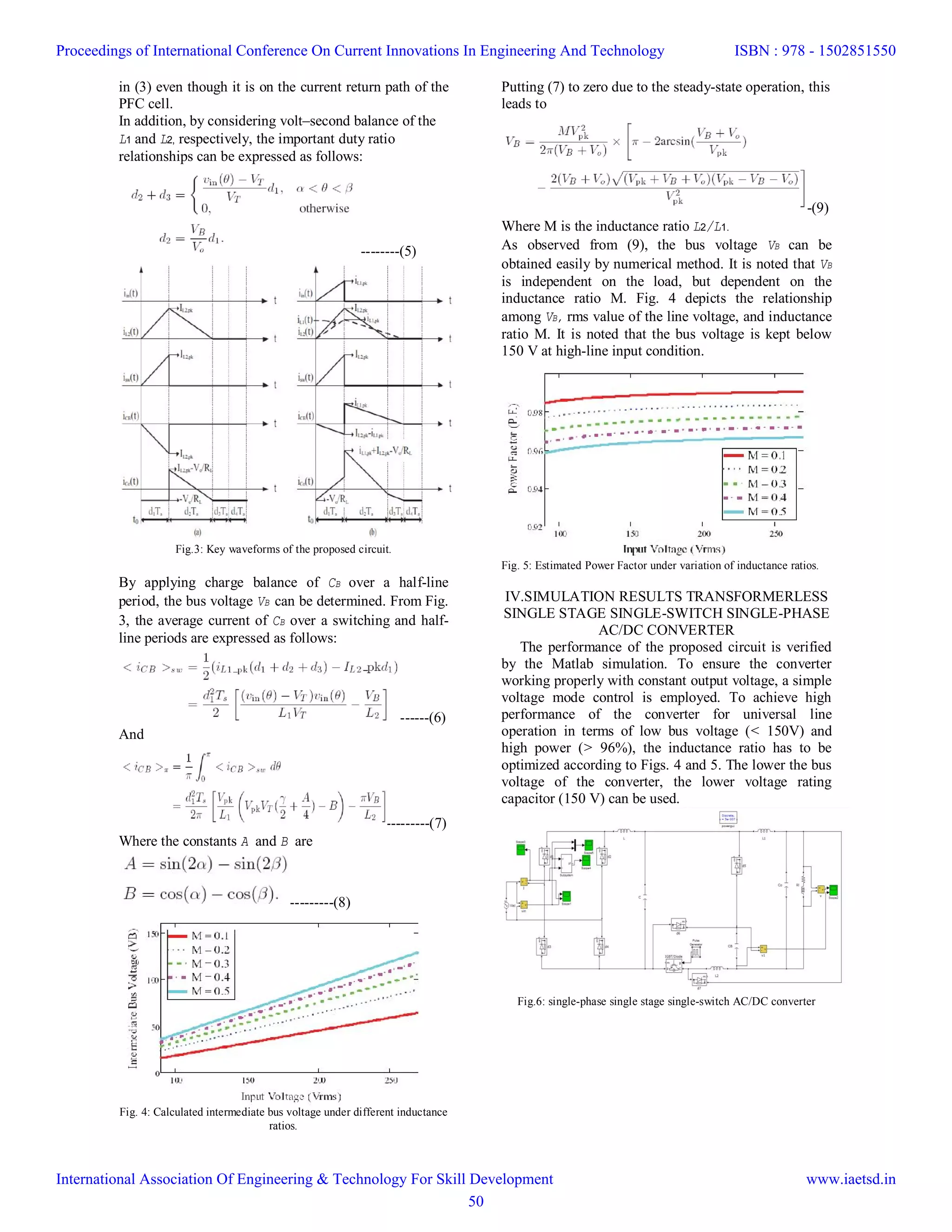
![VI. CONCLUSION
The proposed IBuBuBo three phase single-stage
ac/dc converter with closed loop has been
experimentally verified, and the results have shown
good agreements with the predicted values. Thus the
required DC output voltage was obtained for the
applications with different input ratings. Here, the lower
voltage rating of capacitor can be used. Moreover, the
topology is able to obtain low output voltage without
high step-down transformer. Owing to the absence of
transformer, the demagnetizing circuit, the associated
circuit dealing with leakage inductance and the cost of
the proposed circuit are reduced compared with the
isolated counterparts. In addition. Thanks to the direct
power transfer path in the proposed converter, it is able
to achieve high efficiency around 89%.
REFERENCES
[1] Q. Zhao, F. C. Lee, and F.-s. Tsai, “Voltage and current
stress reduction in single-stage power-factor
correction AC/DC converters with bulk capacitor voltage
feedback,” IEEE Trans. Power Electron., vol. 17, no. 4,
pp. 477–484, Jul. 2002.
[2] O. Garcia, J. A. Cobos, R. Prieto, P. Alou, and J. Uceda,
“Single phase power factor correction: A survey,” IEEE
Trans. Power Electron., vol. 18, no. 3, pp. 749–755, May
2003.
[3] S. Luo,W. Qiu,W.Wu, and I. Batarseh, “Flyboost power
factor correction cell and a new family of single-stage
AC/DC converters,” IEEE Trans. Power Electron., vol.
20, no. 1, pp. 25–34, Jan. 2005.
[4] D. D. C. Lu, H. H. C. Iu, and V. Pjevalica, “A Single-
Stage AC/DC converterWith high power factor, regulated
bus voltage, and output voltage,” IEEE Trans. Power
Electron., vol. 23, no. 1, pp. 218–228, Jan. 2008.
[5] M. K. H. Cheung, M. H. L. Chow, and C. K. Tse,
“Practical design and evaluation of a 1 kW PFC power
supply based on reduced redundant power processing
principle,” IEEE Trans. Ind. Electron., vol. 55, no. 2, pp.
665–673, Feb. 2008.
[6] D. D. C. Lu, H. H. C. Iu, and V. Pjevalica, “Single-Stage
AC/DC Boost: Forward converter with high power factor
and regulated bus and output voltages,” IEEE Trans. Ind.
Electron., vol. 56, no. 6, pp. 2128–2132, Jun. 2009.
Proceedings of International Conference On Current Innovations In Engineering And Technology
International Association Of Engineering & Technology For Skill Development
ISBN : 978 - 1502851550
www.iaetsd.in
52](https://image.slidesharecdn.com/iaetsd-atransformerlesssingle-stage-150407220428-conversion-gate01/75/Iaetsd-a-transformerless-single-stage-5-2048.jpg)


![[IJET V2I5P8] Authors: Lakshmi K R, Kavitha Issac, Kiran Boby](https://cdn.slidesharecdn.com/ss_thumbnails/ijet-v2i5p8-161107140749-thumbnail.jpg?width=640&height=640&fit=bounds)