Downloaded 81 times

![REFERENCES
[1] M. F. Mc Granaghan, D. R. Mueller, and M. J.
Samotyi,” V Voltage Sags in Industerial Systems,”
IEEE trans ind. A ppl., vol. 29, no. 2, pp. 397-403,
Mar/Apr. 1996.
[2] A. kara, P . Dabler, D. Amhof , and H.
Gruning” Power Supply Quality Improvement
with A Dynamic Restorer (DVR)”, in proc .13
Annu .APEC (cat no 98CH36154), An aheim, ca,
1998, PP. 986-993
[3] L. Gyugyi, C. D. Schauder, C. W . Edwards
and M.Sarkozii, ”Apparatus and Method for
Dynamic Voltage Restoration of Utility Distribution
Network ,”US. pattent 5 329 222, Jul. 1994](https://image.slidesharecdn.com/b7-150417032949-conversion-gate02/85/DESIGN-OF-MATRIX-CONVERTER-BASED-DYNAMIC-VOLTAGE-RESTORER-FOR-POWER-QUALITY-ENHANCEMENT-16-320.jpg)

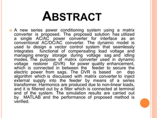
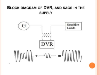
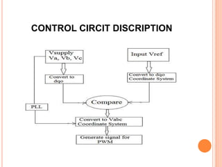
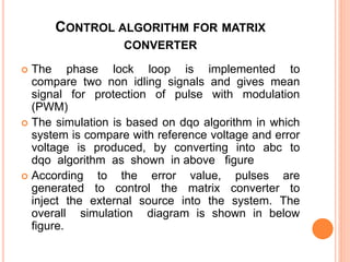
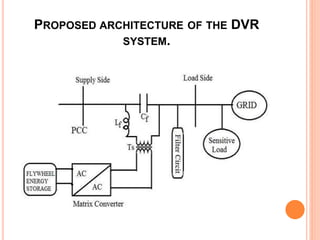
The document proposes a matrix converter-based dynamic voltage restorer (DVR) system for power quality enhancement. The DVR uses a single matrix converter instead of a conventional AC/DC/AC converter. It is connected between the distribution feeder and load to mitigate voltage sags. The control system is based on dqo modeling of the matrix converter. It injects power from an energy storage device like a flywheel to restore the load voltage during sags. Simulation results show the DVR is able to effectively reduce sags and regulate the supply voltage, improving power quality.