1. This document discusses various analog modulation techniques used to transmit digital data, including ASK, FSK, PSK, and QAM.
2. It provides examples and explanations of how each technique works, such as varying the amplitude (ASK), frequency (FSK), or phase (PSK) of a carrier signal to represent the 1s and 0s of digital data.
3. QAM is described as a technique that modulates signals onto both the cosine (in-phase) and sine (quadrature-phase) components of a carrier, allowing it to encode multiple bits per symbol.


![6
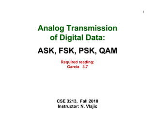
Modulation of Digital Data: ASK (cont.)
Example [ ASK ]
vd(t)
vc(t)
vASK(t)
How does the frequency spectrum of vASK(t) look like!?
fvd(f) vc(f)](https://image.slidesharecdn.com/c9yz2kqqtwgm5ioato6r-signature-f4f31619a311d8af48ab9bb969f8db516b90b81d92cd79deba1fba84cb96193c-poli-170425194143/85/Digital-modulation-6-320.jpg)
![7
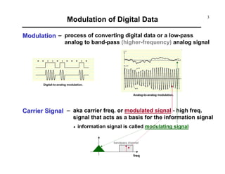
Modulation of Digital Data: ASK (cont.)
ASKASK--Modulated Signal: Frequency SpectrumModulated Signal: Frequency Spectrum
t)cos(ωt)fcos(2(t)v ccc == π
⎥
⎦
⎤
⎢
⎣
⎡
−+−+⋅= ...tcos5ω
5π
2
tcos3ω
3π
2
tcosω
π
2
2
1
A(t)v 000d
Carrier signal: , where 2πfc=ωc
Digital signal:
(unipolar!!!)
ωc ωωd_max
Modulated signal:
( ) ( )[ ]
( ) ( )[ ] ...t3ωωcost3ωωcos
3π
1
-tωωcostωωcos
π
1
tcosω
2
1
...tcos3ωtcosω
3π
2
-tcosωtcosω
π
2
tcosω
2
1
...tcos5ω
5π
2
tcos3ω
3π
2
tcosω
π
2
2
1
tcosω
(t)v(t)v(t)v
0c0c
0c0cc
0c0cc
000c
dcASK
+++−−
++−+=
=+⋅⋅+=
=⎥
⎦
⎤
⎢
⎣
⎡
−+−+⋅=
=⋅=
( )B)cos(AB)-cos(A
2
1
cosBcosA ++=⋅
ωc ωωc+ωd_maxωc-ωd_max](https://image.slidesharecdn.com/c9yz2kqqtwgm5ioato6r-signature-f4f31619a311d8af48ab9bb969f8db516b90b81d92cd79deba1fba84cb96193c-poli-170425194143/85/Digital-modulation-7-320.jpg)
![9
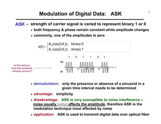
Modulation of Digital Data: FSK (cont.)
Example [ FSK ]
vd(t)
vc1(t)
vc2(t)
vFSK(t)
ω1 ωωd_max ω2
ω1 ωω1-ωd_max
ω2 ω2+ωd_max](https://image.slidesharecdn.com/c9yz2kqqtwgm5ioato6r-signature-f4f31619a311d8af48ab9bb969f8db516b90b81d92cd79deba1fba84cb96193c-poli-170425194143/85/Digital-modulation-9-320.jpg)
![10
Modulation of Digital Data: FSK (cont.)
FSKFSK--Modulated Signal: Frequency SpectrumModulated Signal: Frequency Spectrum
(t)vd
Digital signal: - modulated with ω1 , and
- modulated with ω2
Modulated signal:
( ) ( )[ ]
( ) ( )[ ]
( ) ( )[ ]
( ) ( )[ ] ++++−+
++−−
++++−−
++−+=
=
=⎥⎦
⎤
⎢⎣
⎡
−−+−⋅+
+⎥
⎦
⎤
⎢
⎣
⎡
−+−+⋅=
=−⋅+⋅=
...t3ωωcost3ωωcos
3π
1
-tωωcostωωcos
π
1
tcosω
2
1
...t3ωωcost3ωωcos
3π
1
-tωωcostωωcos
π
1
tcosω
2
1
...tcos5ω
5π
2
tcos3ω
3π
2
tcosω
π
2
2
1
tcosω
...tcos5ω
5π
2
tcos3ω
3π
2
tcosω
π
2
2
1
tcosω
(t))vtcosω(t)vtcosω(t)v
0202
02022
0101
01011
0002
0001
d2d1FSK
...
1(
(t)v1-(t)'v dd =](https://image.slidesharecdn.com/c9yz2kqqtwgm5ioato6r-signature-f4f31619a311d8af48ab9bb969f8db516b90b81d92cd79deba1fba84cb96193c-poli-170425194143/85/Digital-modulation-10-320.jpg)
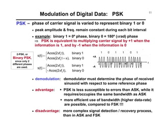
![12
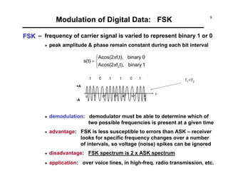
Modulation of Digital Data: PSK (cont.)
Example [ PSK ]
vd(t)
vc(t)
vPSK(t)
ωc ωωd_max ωc ωωc+ωd_maxωc-ωd_max](https://image.slidesharecdn.com/c9yz2kqqtwgm5ioato6r-signature-f4f31619a311d8af48ab9bb969f8db516b90b81d92cd79deba1fba84cb96193c-poli-170425194143/85/Digital-modulation-12-320.jpg)
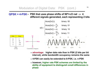
![13
Modulation of Digital Data: PSK (cont.)
PSK DetectionPSK Detection – multiply the received / modulated signal
by 2*cos(2πfct)
• resulting signal
• by removing the oscillatory part with a
low-pass filter, the original baseband signal
(i.e. the original binary sequence) can be
easily determined
[ ] 1binary,t)fcos(41At)f(22Acos cc
2
ππ +=
[ ] 0binary,t)fcos(41At)f(22Acos- cc
2
ππ +−=
t)fAcos(2 cπ±
( )2Acos1
2
1
Acos2
+=](https://image.slidesharecdn.com/c9yz2kqqtwgm5ioato6r-signature-f4f31619a311d8af48ab9bb969f8db516b90b81d92cd79deba1fba84cb96193c-poli-170425194143/85/Digital-modulation-13-320.jpg)

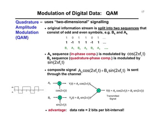
![15
Modulation of Digital Data: PSK (cont.)
B
fc+B
f
f
fc-B fc
• If bandpass channel has bandwidth Wc [Hz],
then baseband channel has Wc/2 [Hz] available, so
modulation system supports 2*(Wc/2) = Wc [pulses/second]
recall Nyqyist Law: baseband transmission system of bandwidth Wc [Hz]
can theoretically support 2 Wc pulses/sec
Facts from Modulation TheoryFacts from Modulation Theory
Wc
Wc/2
Baseband signal x(t) with
bandwidth Wc/2
If
then
Modulated signal
x(t)cos(2πfct) has
bandwidth Wc Hz
How can we recover the factor 2 in supported data-rate !?
Data rate = 2*Wc/2 = B [bps]](https://image.slidesharecdn.com/c9yz2kqqtwgm5ioato6r-signature-f4f31619a311d8af48ab9bb969f8db516b90b81d92cd79deba1fba84cb96193c-poli-170425194143/85/Digital-modulation-15-320.jpg)
![18
Modulation of Digital Data: QAM (cont.)
Example [ QAM ]
Bk
vd(t)
Ak
sin(ωct)
cos(ωct)](https://image.slidesharecdn.com/c9yz2kqqtwgm5ioato6r-signature-f4f31619a311d8af48ab9bb969f8db516b90b81d92cd79deba1fba84cb96193c-poli-170425194143/85/Digital-modulation-18-320.jpg)


![22
Ak
Bk
Ak
Bk
Modulation of Digital Data: QAM
1616--level QAMlevel QAM – the number of bits transmitted per T [sec] interval
can be further increased by increasing the number
of levels used
• in case of 16-level QAM, Ak and Bk individually can
assume 4 different levels: -1, -1/3, 1/3, 1
• data rate: 4 bits/pulse ⇒ 4W bits/second
( ) )
A
B
tantfcos(2BAt)fsin(2Bt)fcos(2AY(t)
k
k1-
ckkckck ++=+= πππ 2
1
22
In QAM various combinations of amplitude and phase are employed
to achieve higher digital data rates.
Amplitude changes are susceptible to noise ⇒ the number of phase shifts used
by a QAM system is always greater than the number of amplitude shifts.
Ak and Bk individually
can take on 4 different values;
the resultant signal can take
on (only) 3 different values!!!](https://image.slidesharecdn.com/c9yz2kqqtwgm5ioato6r-signature-f4f31619a311d8af48ab9bb969f8db516b90b81d92cd79deba1fba84cb96193c-poli-170425194143/85/Digital-modulation-22-320.jpg)