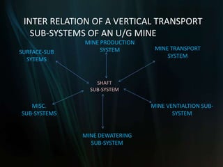
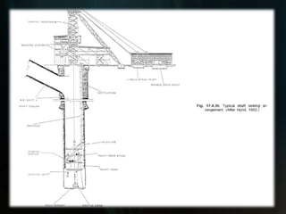
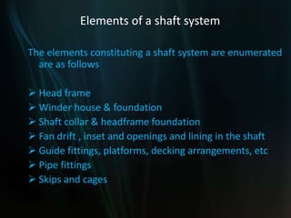
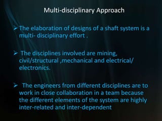
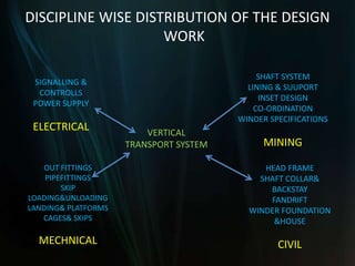
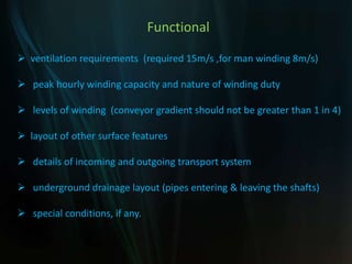
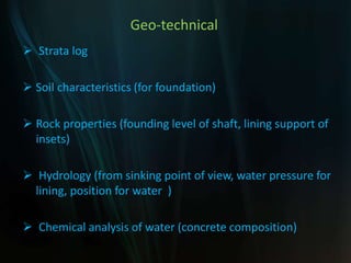
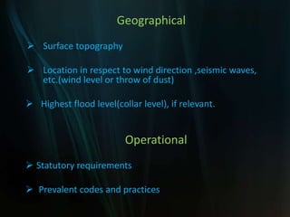
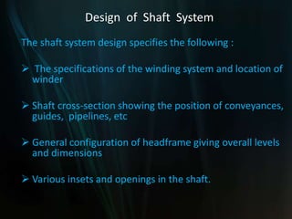
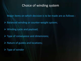
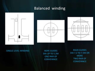
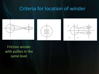
Designing a shaft system
Inter-relation of Shaft Sub-system with other
sub-systems
A Shaft system is a sub-system of the mine as a
whole .
It is functionally inter–related to many other sub-
systems, of which some of the important ones
could be identified as follows:
 Mine transport
 Mine ventilation
 Dewatering
 Production
 Surface arrangements, etc.
INTER RELATION OF A VERTICAL TRANSPORT
SUB-SYSTEMS OF AN U/G MINE
MINE PRODUCTION
SYSTEM
MINE DEWATERING
SUB-SYSTEM
MINE VENTIALTION SUB-
SYSTEM
MINE TRANSPORT
SYSTEM
MISC.
SUB-SYSTEMS
SURFACE-SUB
SYTEMS
SHAFT
SUB-SYSTEM
Elements of a shaft system
The elements constituting a shaft system are enumerated
are as follows
 Head frame
 Winder house & foundation
 Shaft collar & headframe foundation
 Fan drift , inset and openings and lining in the shaft
 Guide fittings, platforms, decking arrangements, etc
 Pipe fittings
 Skips and cages
Multi-disciplinary Approach
The elaboration of designs of a shaft system is a
multi- disciplinary effort .
 The disciplines involved are mining,
civil/structural ,mechanical and electrical/
electronics.
 The engineers from different disciplines are to
work in close collaboration in a team because
the different elements of the system are highly
inter-related and inter-dependent
DISCIPLINE WISE DISTRIBUTION OF THE DESIGN
WORK
HEAD FRAME
SHAFT COLLAR&
BACKSTAY
FANDRIFT
WINDER FOUNDATION
&HOUSE
CIVIL
SHAFT SYSTEM
LINING & SUUPORT
INSET DESIGN
CO-ORDINATION
WINDER SPECIFICATIONS
MINING
OUT FITTINGS
PIPEFITTINGS
SKIP
LOADING&UNLOADING
LANDING& PLATFORMS
CAGES& SKIPS
MECHNICAL
SIGNALLING &
CONTROLLS
POWER SUPPLY
ELECTRICAL VERTICAL
TRANSPORT SYSTEM
Workload and Inputs Required
Three basic inputs for the design work are
 Expertise: The expertise means the know-how which
consists of a clear understanding of functional
requirements, the design criteria to be applied
and knowledge of prevalent design codes and
norms.
 Establishment : The establishment would include a well-
equipped design office , sufficient number of
design engineers and drawing office staff.
 Expenses: While the man days required to be spent on the
design of a shaft system would depend on the
magnitude and complexity of individual task
Workload and Inputs Required
The distribution of time under the different design
aspects is given below:-
 Functional design ------ 20%
 Design criteria ------- 5%
 Engineering calculations ----- 25 %
 Preparation of drawings ----- 50%
Basic technical data required
 Before taking – up the design work of a shaft system,
considerable basic data is required to be collected.
 This basic data could be grouped under four
categories . They are
 Functional
 Geo-technical
 Geographical
 Operational.
Functional
 ventilation requirements (required 15m/s ,for man winding 8m/s)
 peak hourly winding capacity and nature of winding duty
 levels of winding (conveyor gradient should not be greater than 1 in 4)
 layout of other surface features
 details of incoming and outgoing transport system
 underground drainage layout (pipes entering & leaving the shafts)
 special conditions, if any.
Geo-technical
 Strata log
 Soil characteristics (for foundation)
 Rock properties (founding level of shaft, lining support of
insets)
 Hydrology (from sinking point of view, water pressure for
lining, position for water )
 Chemical analysis of water (concrete composition)
Geographical
 Surface topography
 Location in respect to wind direction ,seismic waves,
etc.(wind level or throw of dust)
 Highest flood level(collar level), if relevant.
Operational
 Statutory requirements
 Prevalent codes and practices
Design of Shaft System
The shaft system design specifies the following :
 The specifications of the winding system and location of
winder
 Shaft cross-section showing the position of conveyances,
guides, pipelines, etc
 General configuration of headframe giving overall levels
and dimensions
 Various insets and openings in the shaft.
Choice of winding system
Major items on which decision is to be made are as follows :
 Balanced winding or counter-weight system;
 Winding cycle and payload;
 Type of conveyance and dimensions;
 Nature of guides and locations;
 Type of winder
Balanced winding or counter weight-system
 However, if winding from several levels is to be done
frequently, a counter-weight system is chosen.
 In some special situations when more than one winding
plant has to be provided in one shaft or a large size cage
is to be accommodated, counter-weight system is
chosen from space considerations in the shaft.
SINGLE LEVEL WINDING ROPE GUIDES
DIA UP TO 5.2M
ONE PAIR OF
CONVEYANCE
RIGID GUIDES
DIA 7.2 TO 7.5M OR
MORE
TWO PAIR OF
CONVEYANCE
Balanced winding
MULTI LEVEL
WINDING
RIGID GIDES DIA 6.5M
ONE PAIR OF SKIP
SINGLE CASE WITH COUNTER
WEIGHT
ROPE GUIDES
DIA<4.8M
SINGLE CASE WITH
CUNTER WEIGHT
Single level winding
Winding cycle and pay load
 The greater the payload and smaller the speed , safer and more
efficient is the wind.
 The peak power requirement also goes down with the speed.
 The size of the conveyance, rope and winding machine will
become larger and more expensive with the increase in payload.
 Theoretical winding cycle indicating the period of acceleration
and deceleration and the constant winding speed can be worked
out after providing for the decking time.
Winding cycle and pay load
 However, the theoretical winding cycle is required to
modified from practical operational considerations by
providing additional time
 This is to ensure smooth starting and stopping operations as
well as change over from the acceleration and deceleration
periods to the period of constant speed.
 Once the winding cycle is decided, with the help of the peak
hourly winding capacity, the payload can be worked out.
Type of winder
Friction winders
 In case of friction winders the ratio of the rope tensions on the
loaded and empty sides are to be maintained all the time
 For depths less than 300 metres, use of friction winder is not
advantageous from the fact that
 The ratio of rope tensions in the static state is limited to 50%
of the suspended weight on the rope
 The pay load thus gets very limited in this case
 For greater depths and within prevalent depth ranges of the
present day coal mining industry friction winders would be more
advantageous
Type of winder
Friction winders
 In case of a friction winder the conveyance cannot be decked
on keeps or platforms and the conveyance all the time
remains suspended on the rope.
 Due to rope stretch the position of the conveyance varies
according to the load in conveyance and, therefore, for
friction winders operating cages elaborate decking
arrangements involving use of swinging platforms, pusher
rams etc. are to be made.
 Balance rope being an essential item of friction winder the
conveyance is to be designed to sustain the load of balance
rope.
Type of winder
Friction winders
 In case of friction winder according to requirement of
payload and depth a single rope or multi-rope friction
winder can be chosen.
Multi -rope winder
 A multi-rope winder results in the reduction in the size of
mechanical parts of winder and thereby in the cost of
the winder
Location of winder
 limitations of fleet angle and the rope angle are deciding
factors for location of winder
 In case of friction winder the alternative of locating the
winder on the top of the headframe should also be
examined.
 Location on the head frame can be sufficiently
competitive, If the diameter of the drum of a multi-rope
friction winder is such that it can be installed on the
headframe without use of deflection pulleys then in that
Location of winder
 If sufficient space is available the ground location is
preferred and is economical.
 In case of ground mounting of friction winders it is
preferred to keep the fleet angle very low.
 With this objective, the two winding pulleys are
located at different levels and the winding machine is
located at right angles to the longer axis of the
conveyance, thereby eliminating the fleet angle
completely.
Friction winder
with pullies in the
same plane
Criteria for location of winder
Friction winder
with pullies in the
same level
Criteria for location of winder
Type of conveyance and dimensions
 Simultaneous decking of more than one deck of the cage
for changing of tubs/mine cars requires elaborate car
handling arrangements involving considerable
expenditure.
 T he ratio of payload to dead load in cage winding system
is also rather unfavourable.
 whenever the production envisaged from a single pit is 0.6
m. tonnes or more per annum, the choice leans heavily in
favour of skip winding.
Type of conveyance and dimensions
 For men and material winding single or multi-deck
cages are chosen according to duty requirement
 For men winding the attempt should be to lower the
men in the major shift in 30 minutes.
 The most common base dimension of cages and skips
are equivalent to those of a commonly used tandem
tub cage.
Type of conveyance and dimensions
 While for man winding simultaneous decking of more
than one deck is considered, the material cars are
normally handed only from one level to which different
deck of the cages are levelled in succession.
 For the base dimensions of cage the prevailing
dimensions of tubs/mine cars are considered. The base
dimensions of cages and skips are generally kept the
same.
Nature of guides
 If it is possible to provide adequate clearances between
the conveyances and the conveyance and the sides of
shaft rope guides are preferred due to low cost and ease
of installation.
 Otherwise rigid guides are chosen.
 In case of multi-level winding where a counter weight
system is adopted rigid guides are used for the
conveyance and rope guides are provided for the counter-
weight.
General configuration of head frame
 The main purpose of the headframe is to support winding
sheaves provided for directing the winding ropes
connected to the conveyances in the shaft towards the
winding engine.
 In case of tower mounted winder the winder is in the line
of movement of conveyance and no winding sheaves are
necessary. In such a case the purpose of headframe is to
support the winder itself.
 The height of the winding sheaves depend on the height
to which the conveyance is to be normally raised and the
extra over run distance to be provided for safety.
General configuration of head frame
 The headframe to also provide support for the
guiding arrangements of the conveyance for its
movement above ground and the safety devices like
over winding protection, fences and gates.
 The head frame structure has to provide adequate
openings for the movement of men and material to
and from the conveyances.
General configuration of head frame
 head frames are broadly categorised into two distinct groups :
i) Conventional British type of head frame :
 The British type of head frame is more rigid and less amenable
to adjustments on account of strata movements in the vicinity of
the shaft.
 At the same time it is more economical from the point of view
of erection as well as construction costs
ii) Head frames popularly adopted on the European Continent.
 The head frame commonly used on the European Continent is
more flexible and can be easily adjusted in case of any strata
movement in the vicinity of the shaft.
 On the other hand it is more difficult to erect and is more costly.
Types of HeadFrames
British type
Types of Headframes
Continental Type
Various insets and openings in the shaft
 The size of the opening is decided on the basis of following :
 Clearances required between tubs/mine cars and between
tubs/mine cars and the sides also for passage of men in man
winding shafts
 In case of simultaneous decking of more than one deck of the
cage the height is to be decided in relation to the position of such
decks
 Dimensions required for passage of ventilation air and suitable
shape for smooth change in the direction of air current
 Dimensions necessary for handling long materials.
Various insets and openings in the shaft
 The position for the skip loading arrangement is located in
relation to the overall transport arrangements in the mine
and in relation to the following aspects.
 Location of the bunker from which the measuring
pockets/loading conveyors are to be fed.
 Size of the measuring pockets.
 C or S arrangement for loading and un loading.
Various insets and openings in the shaft
 The location and size of ventilation opening is to be
decided on following considerations:
 Quantity of ventilation air.
 Position of conveyances in the shaft the lowest
possible position of conveyance while decking.
 Position of foundation of shaft collar.
Criteria for design of Insets
Winder foundation
Basic data required
1) Frame dimension of winder and component layout;
2) Static load detail of important components
3) Dynamic load details;
4) Soil / rock characteristics
Design procedure
1) On the basis of dimensions of the winder and oil/rock characteristics,
length ,breadth of foundation is decided;
2) Centre of gravity of foundation block with machine components is
ascertained
Design procedure
3) Geometrical inertia and location of neutral axis is worked out;
4) Maximum pressure on rock/soil based on static load and
overturning moments is worked out and compared with
permissible pressure.
5) Steps 2 and 4 are repeated for different combinations of
dynamic load and in each case the founding pressure should be
less than the permissible limit.
6) Foundation is checked for horizontal sliding.
7) Anchorage strength of individual components is checked.
Head frame
The head frame structure is designed to withstand
event of rope rupture.
 Two extreme case are considered viz.,
 Conveyance getting stuck-up in the shaft.
 Conveyance getting stuck-up in the head frame.
The stresses distribution in all members is worked
out and compared with permissible stress limits.
Head frame
 In case of drum winders the beams supporting the bell
plate of safety detaching hook are designed to
withstand 3 times the weight of the loaded cage or skip.
 In case of friction winder the buffer beams are designed
to withstand the forces in the event of rope rupture.
 The beams supporting the catches for holding the
conveyance are designed to sustain five times the
weight of a loaded conveyance
Stresses when conveyance is stuck up in the
skip
Criteria for designing a Headframe
Stresses when the conveyance is stuck up
in the head frame
Criteria for designing a Headframe
Conveyance
 For cages the hangers are designed for a factor of safety
of 10.
 The hangers are also to be checked in this case against
buckling.
 The arrangement of unloading gates and emergency
man riding are also to be selected and designed
Designing a Cage
Designing a Cage
Shaft Collar
Purpose of the shaft collar
 To provide support against loose strata near the surfaces;
 Where front legs of the head frame rest on the collar to act as their
foundation.
Design procedure
 The collar is to be founded on good rock.
 Foundation is to withstand self-weight of the collar and in appropriate cases
weight of the head frame as well as the dynamic loads in the event of rope
rupture.
 For deep founding level the collar is also to be considering as a column and
analysed accordingly .
 While designing collar appropriate openings are to be left for ventilation drift,
and for taking out pipe ranges and cables as well as for installation of decking
equipment
Other elements
 There are various types of shaft linings viz., brick work,
monolithic concrete lining, reinforce concrete,
prefabricated segments of steel or concrete, gunniting
etc.
 If strata layer is anticipated a special layer of material
like bitumen is to be inserted between the strata and
lining to permit free movement.
 Special type of lining is also required to be provided if
water seepage is to be completely prevented.
Other elements
 Sizes of pipelines are to be chosen according to the quantity of water
required to be handled and the thickness of the pipe range depends
upon the static and dynamic head.
 Once these parameters are decided, the supports can be designed on
the basis of the load of the range.
 In some of the cases expansion joints are also considered if
appreciable seasonal temperature variations are anticipated in the
shaft.
 Rigid guides have to withstand the horizontal and vertical forces due
to the movement of the conveyance and these guides and their
supports are to be designed taking these aspects into consideration.
 Extra provision is also required to be made against weakening due to
corrosion.
Shaft outfittings
Shaft outfittings
Pipe supports in the shafts
Conclusion
The overall life requirement also influences the
design
 For an economic design the general inclination
towards over-design has to be avoided without
sacrificing the safety aspect.
 However, there are areas of design where as yet a
clear understanding about the forces coming into
play is lacking and there is a conflict about the
appropriate design criteria to be adopted.
Conclusion
 In such situation, it may be necessary to adopt an over design
so as to be absolute sure about the safety aspect
 As the elemental design is to be integrated in the overall system
and the different elements are being designed by different
design engineers a constant coordination is required to see that
the various element so designed are properly fitting in, in the
overall system.
 In this process there are many occasions where various
elemental designs are revised.
MECHANISED SINKING
Preparatory work
 The chosen shaft site to be connected by an all weather road to the
main road.
 A network of roads to be constructed within the main area for
efficient transport.
 Adequate power supply and water supply to be made available (1 to
1.5 MVA substation).
 A general plan of the surface to be prepared showing both
permanent and temporary service and residential buildings and
structures( roads, dump yard, etc) .
 structures to be so located that they do not interfere with permanent
structures to be built later.
MECHANISED SINKING
Preparatory work
 Fixing the centre of the shaft and its axes , bench marks etc.
 With the help of permanent survey points at locations where these
will not be disturbed.
 Contour plan of the area at 1m interval for about 500m from the
shaft.
 The site to be levelled whenever needed and temporary and
permanent structures to be erected
Dealing with water in a sinking shaft
Rate of water flow Method of removal of water
• *Upto 2 cu.m/hr ----- in kibbles filled with the help of
buckets. Removed with the debris.
• *Upto 5 cu.m/hr ----- Shallow shaft—in kibbles which are
filled by light pumps (1.5cu.m/trip)
Deep shaft – Suspended sinking
pumps.
Dealing with water in a sinking shaft
Rate of water flow Method of removal of water
*5 – 50 cu.m/hr ----- Shallow shaft (<250 m )
Suspended sinking pumps.
Deep shaft (>250 m )—
shaft pumping.
•
• *>50 cu.m/hr ------ Probably it will be more
economical to seal off the
water by cementation
– if ground condition permit
cementation.
• ** Balance the cost and time in cementation against the cost of pumping.

Designing a shaft system

  • 2.
  • 3.
    Inter-relation of ShaftSub-system with other sub-systems A Shaft system is a sub-system of the mine as a whole . It is functionally inter–related to many other sub- systems, of which some of the important ones could be identified as follows:  Mine transport  Mine ventilation  Dewatering  Production  Surface arrangements, etc.
  • 4.
    INTER RELATION OFA VERTICAL TRANSPORT SUB-SYSTEMS OF AN U/G MINE MINE PRODUCTION SYSTEM MINE DEWATERING SUB-SYSTEM MINE VENTIALTION SUB- SYSTEM MINE TRANSPORT SYSTEM MISC. SUB-SYSTEMS SURFACE-SUB SYTEMS SHAFT SUB-SYSTEM
  • 6.
    Elements of ashaft system The elements constituting a shaft system are enumerated are as follows  Head frame  Winder house & foundation  Shaft collar & headframe foundation  Fan drift , inset and openings and lining in the shaft  Guide fittings, platforms, decking arrangements, etc  Pipe fittings  Skips and cages
  • 7.
    Multi-disciplinary Approach The elaborationof designs of a shaft system is a multi- disciplinary effort .  The disciplines involved are mining, civil/structural ,mechanical and electrical/ electronics.  The engineers from different disciplines are to work in close collaboration in a team because the different elements of the system are highly inter-related and inter-dependent
  • 8.
    DISCIPLINE WISE DISTRIBUTIONOF THE DESIGN WORK HEAD FRAME SHAFT COLLAR& BACKSTAY FANDRIFT WINDER FOUNDATION &HOUSE CIVIL SHAFT SYSTEM LINING & SUUPORT INSET DESIGN CO-ORDINATION WINDER SPECIFICATIONS MINING OUT FITTINGS PIPEFITTINGS SKIP LOADING&UNLOADING LANDING& PLATFORMS CAGES& SKIPS MECHNICAL SIGNALLING & CONTROLLS POWER SUPPLY ELECTRICAL VERTICAL TRANSPORT SYSTEM
  • 9.
    Workload and InputsRequired Three basic inputs for the design work are  Expertise: The expertise means the know-how which consists of a clear understanding of functional requirements, the design criteria to be applied and knowledge of prevalent design codes and norms.  Establishment : The establishment would include a well- equipped design office , sufficient number of design engineers and drawing office staff.  Expenses: While the man days required to be spent on the design of a shaft system would depend on the magnitude and complexity of individual task
  • 10.
    Workload and InputsRequired The distribution of time under the different design aspects is given below:-  Functional design ------ 20%  Design criteria ------- 5%  Engineering calculations ----- 25 %  Preparation of drawings ----- 50%
  • 11.
    Basic technical datarequired  Before taking – up the design work of a shaft system, considerable basic data is required to be collected.  This basic data could be grouped under four categories . They are  Functional  Geo-technical  Geographical  Operational.
  • 12.
    Functional  ventilation requirements(required 15m/s ,for man winding 8m/s)  peak hourly winding capacity and nature of winding duty  levels of winding (conveyor gradient should not be greater than 1 in 4)  layout of other surface features  details of incoming and outgoing transport system  underground drainage layout (pipes entering & leaving the shafts)  special conditions, if any.
  • 13.
    Geo-technical  Strata log Soil characteristics (for foundation)  Rock properties (founding level of shaft, lining support of insets)  Hydrology (from sinking point of view, water pressure for lining, position for water )  Chemical analysis of water (concrete composition)
  • 14.
    Geographical  Surface topography Location in respect to wind direction ,seismic waves, etc.(wind level or throw of dust)  Highest flood level(collar level), if relevant. Operational  Statutory requirements  Prevalent codes and practices
  • 15.
    Design of ShaftSystem The shaft system design specifies the following :  The specifications of the winding system and location of winder  Shaft cross-section showing the position of conveyances, guides, pipelines, etc  General configuration of headframe giving overall levels and dimensions  Various insets and openings in the shaft.
  • 16.
    Choice of windingsystem Major items on which decision is to be made are as follows :  Balanced winding or counter-weight system;  Winding cycle and payload;  Type of conveyance and dimensions;  Nature of guides and locations;  Type of winder
  • 17.
    Balanced winding orcounter weight-system  However, if winding from several levels is to be done frequently, a counter-weight system is chosen.  In some special situations when more than one winding plant has to be provided in one shaft or a large size cage is to be accommodated, counter-weight system is chosen from space considerations in the shaft.
  • 18.
    SINGLE LEVEL WINDINGROPE GUIDES DIA UP TO 5.2M ONE PAIR OF CONVEYANCE RIGID GUIDES DIA 7.2 TO 7.5M OR MORE TWO PAIR OF CONVEYANCE Balanced winding
  • 19.
    MULTI LEVEL WINDING RIGID GIDESDIA 6.5M ONE PAIR OF SKIP SINGLE CASE WITH COUNTER WEIGHT ROPE GUIDES DIA<4.8M SINGLE CASE WITH CUNTER WEIGHT Single level winding
  • 20.
    Winding cycle andpay load  The greater the payload and smaller the speed , safer and more efficient is the wind.  The peak power requirement also goes down with the speed.  The size of the conveyance, rope and winding machine will become larger and more expensive with the increase in payload.  Theoretical winding cycle indicating the period of acceleration and deceleration and the constant winding speed can be worked out after providing for the decking time.
  • 21.
    Winding cycle andpay load  However, the theoretical winding cycle is required to modified from practical operational considerations by providing additional time  This is to ensure smooth starting and stopping operations as well as change over from the acceleration and deceleration periods to the period of constant speed.  Once the winding cycle is decided, with the help of the peak hourly winding capacity, the payload can be worked out.
  • 22.
    Type of winder Frictionwinders  In case of friction winders the ratio of the rope tensions on the loaded and empty sides are to be maintained all the time  For depths less than 300 metres, use of friction winder is not advantageous from the fact that  The ratio of rope tensions in the static state is limited to 50% of the suspended weight on the rope  The pay load thus gets very limited in this case  For greater depths and within prevalent depth ranges of the present day coal mining industry friction winders would be more advantageous
  • 23.
    Type of winder Frictionwinders  In case of a friction winder the conveyance cannot be decked on keeps or platforms and the conveyance all the time remains suspended on the rope.  Due to rope stretch the position of the conveyance varies according to the load in conveyance and, therefore, for friction winders operating cages elaborate decking arrangements involving use of swinging platforms, pusher rams etc. are to be made.  Balance rope being an essential item of friction winder the conveyance is to be designed to sustain the load of balance rope.
  • 24.
    Type of winder Frictionwinders  In case of friction winder according to requirement of payload and depth a single rope or multi-rope friction winder can be chosen. Multi -rope winder  A multi-rope winder results in the reduction in the size of mechanical parts of winder and thereby in the cost of the winder
  • 25.
    Location of winder limitations of fleet angle and the rope angle are deciding factors for location of winder  In case of friction winder the alternative of locating the winder on the top of the headframe should also be examined.  Location on the head frame can be sufficiently competitive, If the diameter of the drum of a multi-rope friction winder is such that it can be installed on the headframe without use of deflection pulleys then in that
  • 26.
    Location of winder If sufficient space is available the ground location is preferred and is economical.  In case of ground mounting of friction winders it is preferred to keep the fleet angle very low.  With this objective, the two winding pulleys are located at different levels and the winding machine is located at right angles to the longer axis of the conveyance, thereby eliminating the fleet angle completely.
  • 27.
    Friction winder with pulliesin the same plane Criteria for location of winder
  • 28.
    Friction winder with pulliesin the same level Criteria for location of winder
  • 29.
    Type of conveyanceand dimensions  Simultaneous decking of more than one deck of the cage for changing of tubs/mine cars requires elaborate car handling arrangements involving considerable expenditure.  T he ratio of payload to dead load in cage winding system is also rather unfavourable.  whenever the production envisaged from a single pit is 0.6 m. tonnes or more per annum, the choice leans heavily in favour of skip winding.
  • 30.
    Type of conveyanceand dimensions  For men and material winding single or multi-deck cages are chosen according to duty requirement  For men winding the attempt should be to lower the men in the major shift in 30 minutes.  The most common base dimension of cages and skips are equivalent to those of a commonly used tandem tub cage.
  • 31.
    Type of conveyanceand dimensions  While for man winding simultaneous decking of more than one deck is considered, the material cars are normally handed only from one level to which different deck of the cages are levelled in succession.  For the base dimensions of cage the prevailing dimensions of tubs/mine cars are considered. The base dimensions of cages and skips are generally kept the same.
  • 32.
    Nature of guides If it is possible to provide adequate clearances between the conveyances and the conveyance and the sides of shaft rope guides are preferred due to low cost and ease of installation.  Otherwise rigid guides are chosen.  In case of multi-level winding where a counter weight system is adopted rigid guides are used for the conveyance and rope guides are provided for the counter- weight.
  • 33.
    General configuration ofhead frame  The main purpose of the headframe is to support winding sheaves provided for directing the winding ropes connected to the conveyances in the shaft towards the winding engine.  In case of tower mounted winder the winder is in the line of movement of conveyance and no winding sheaves are necessary. In such a case the purpose of headframe is to support the winder itself.  The height of the winding sheaves depend on the height to which the conveyance is to be normally raised and the extra over run distance to be provided for safety.
  • 34.
    General configuration ofhead frame  The headframe to also provide support for the guiding arrangements of the conveyance for its movement above ground and the safety devices like over winding protection, fences and gates.  The head frame structure has to provide adequate openings for the movement of men and material to and from the conveyances.
  • 35.
    General configuration ofhead frame  head frames are broadly categorised into two distinct groups : i) Conventional British type of head frame :  The British type of head frame is more rigid and less amenable to adjustments on account of strata movements in the vicinity of the shaft.  At the same time it is more economical from the point of view of erection as well as construction costs ii) Head frames popularly adopted on the European Continent.  The head frame commonly used on the European Continent is more flexible and can be easily adjusted in case of any strata movement in the vicinity of the shaft.  On the other hand it is more difficult to erect and is more costly.
  • 36.
  • 37.
  • 38.
    Various insets andopenings in the shaft  The size of the opening is decided on the basis of following :  Clearances required between tubs/mine cars and between tubs/mine cars and the sides also for passage of men in man winding shafts  In case of simultaneous decking of more than one deck of the cage the height is to be decided in relation to the position of such decks  Dimensions required for passage of ventilation air and suitable shape for smooth change in the direction of air current  Dimensions necessary for handling long materials.
  • 39.
    Various insets andopenings in the shaft  The position for the skip loading arrangement is located in relation to the overall transport arrangements in the mine and in relation to the following aspects.  Location of the bunker from which the measuring pockets/loading conveyors are to be fed.  Size of the measuring pockets.  C or S arrangement for loading and un loading.
  • 40.
    Various insets andopenings in the shaft  The location and size of ventilation opening is to be decided on following considerations:  Quantity of ventilation air.  Position of conveyances in the shaft the lowest possible position of conveyance while decking.  Position of foundation of shaft collar.
  • 41.
  • 42.
  • 43.
    Winder foundation Basic datarequired 1) Frame dimension of winder and component layout; 2) Static load detail of important components 3) Dynamic load details; 4) Soil / rock characteristics Design procedure 1) On the basis of dimensions of the winder and oil/rock characteristics, length ,breadth of foundation is decided; 2) Centre of gravity of foundation block with machine components is ascertained
  • 44.
    Design procedure 3) Geometricalinertia and location of neutral axis is worked out; 4) Maximum pressure on rock/soil based on static load and overturning moments is worked out and compared with permissible pressure. 5) Steps 2 and 4 are repeated for different combinations of dynamic load and in each case the founding pressure should be less than the permissible limit. 6) Foundation is checked for horizontal sliding. 7) Anchorage strength of individual components is checked.
  • 45.
    Head frame The headframe structure is designed to withstand event of rope rupture.  Two extreme case are considered viz.,  Conveyance getting stuck-up in the shaft.  Conveyance getting stuck-up in the head frame. The stresses distribution in all members is worked out and compared with permissible stress limits.
  • 46.
    Head frame  Incase of drum winders the beams supporting the bell plate of safety detaching hook are designed to withstand 3 times the weight of the loaded cage or skip.  In case of friction winder the buffer beams are designed to withstand the forces in the event of rope rupture.  The beams supporting the catches for holding the conveyance are designed to sustain five times the weight of a loaded conveyance
  • 47.
    Stresses when conveyanceis stuck up in the skip Criteria for designing a Headframe
  • 48.
    Stresses when theconveyance is stuck up in the head frame Criteria for designing a Headframe
  • 49.
    Conveyance  For cagesthe hangers are designed for a factor of safety of 10.  The hangers are also to be checked in this case against buckling.  The arrangement of unloading gates and emergency man riding are also to be selected and designed
  • 50.
  • 51.
  • 52.
    Shaft Collar Purpose ofthe shaft collar  To provide support against loose strata near the surfaces;  Where front legs of the head frame rest on the collar to act as their foundation. Design procedure  The collar is to be founded on good rock.  Foundation is to withstand self-weight of the collar and in appropriate cases weight of the head frame as well as the dynamic loads in the event of rope rupture.  For deep founding level the collar is also to be considering as a column and analysed accordingly .  While designing collar appropriate openings are to be left for ventilation drift, and for taking out pipe ranges and cables as well as for installation of decking equipment
  • 53.
    Other elements  Thereare various types of shaft linings viz., brick work, monolithic concrete lining, reinforce concrete, prefabricated segments of steel or concrete, gunniting etc.  If strata layer is anticipated a special layer of material like bitumen is to be inserted between the strata and lining to permit free movement.  Special type of lining is also required to be provided if water seepage is to be completely prevented.
  • 54.
    Other elements  Sizesof pipelines are to be chosen according to the quantity of water required to be handled and the thickness of the pipe range depends upon the static and dynamic head.  Once these parameters are decided, the supports can be designed on the basis of the load of the range.  In some of the cases expansion joints are also considered if appreciable seasonal temperature variations are anticipated in the shaft.  Rigid guides have to withstand the horizontal and vertical forces due to the movement of the conveyance and these guides and their supports are to be designed taking these aspects into consideration.  Extra provision is also required to be made against weakening due to corrosion.
  • 55.
  • 56.
  • 57.
    Pipe supports inthe shafts
  • 58.
    Pipe supports inthe shafts
  • 59.
    Conclusion The overall liferequirement also influences the design  For an economic design the general inclination towards over-design has to be avoided without sacrificing the safety aspect.  However, there are areas of design where as yet a clear understanding about the forces coming into play is lacking and there is a conflict about the appropriate design criteria to be adopted.
  • 60.
    Conclusion  In suchsituation, it may be necessary to adopt an over design so as to be absolute sure about the safety aspect  As the elemental design is to be integrated in the overall system and the different elements are being designed by different design engineers a constant coordination is required to see that the various element so designed are properly fitting in, in the overall system.  In this process there are many occasions where various elemental designs are revised.
  • 61.
    MECHANISED SINKING Preparatory work The chosen shaft site to be connected by an all weather road to the main road.  A network of roads to be constructed within the main area for efficient transport.  Adequate power supply and water supply to be made available (1 to 1.5 MVA substation).  A general plan of the surface to be prepared showing both permanent and temporary service and residential buildings and structures( roads, dump yard, etc) .  structures to be so located that they do not interfere with permanent structures to be built later.
  • 62.
    MECHANISED SINKING Preparatory work Fixing the centre of the shaft and its axes , bench marks etc.  With the help of permanent survey points at locations where these will not be disturbed.  Contour plan of the area at 1m interval for about 500m from the shaft.  The site to be levelled whenever needed and temporary and permanent structures to be erected
  • 63.
    Dealing with waterin a sinking shaft Rate of water flow Method of removal of water • *Upto 2 cu.m/hr ----- in kibbles filled with the help of buckets. Removed with the debris. • *Upto 5 cu.m/hr ----- Shallow shaft—in kibbles which are filled by light pumps (1.5cu.m/trip) Deep shaft – Suspended sinking pumps.
  • 64.
    Dealing with waterin a sinking shaft Rate of water flow Method of removal of water *5 – 50 cu.m/hr ----- Shallow shaft (<250 m ) Suspended sinking pumps. Deep shaft (>250 m )— shaft pumping. • • *>50 cu.m/hr ------ Probably it will be more economical to seal off the water by cementation – if ground condition permit cementation. • ** Balance the cost and time in cementation against the cost of pumping.