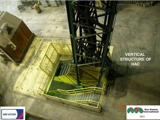
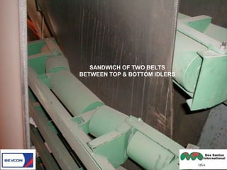
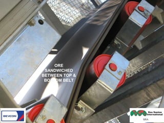
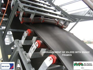
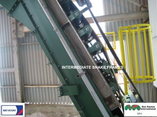
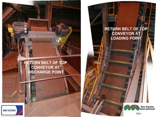
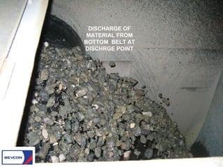
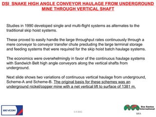
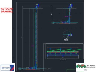
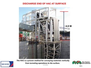
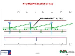
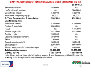
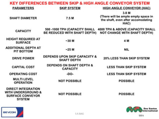
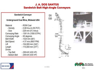
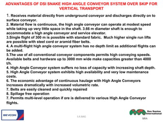
ALTERNATIVE VERTICAL TRANSPORTALTERNATIVE VERTICAL TRANSPORT
FROM UNDERGROUND MINE BY DSIFROM UNDERGROUND MINE BY DSI
SNAKE HIGH ANGLE CONVEYORSNAKE HIGH ANGLE CONVEYOR
(6(6THTH
ASIAN MINING CONGRESS)ASIAN MINING CONGRESS)
(23(23RDRD
TO 27TO 27THTH
FEBRUARY, KOLKATA)FEBRUARY, KOLKATA)
BY S.K.BAGBY S.K.BAG
S.K.BAG
In 1979 the Bureau of Mines, United States Department of the Interior, funded a major study
entitled“High Angle Conveyor Study.
The purpose:
(1) To advance the state-of-the-art in high angle conveying.
(2) To develop high angle conveying systems that would reduce the haulage costs in open pit
mines.
The study was awarded to a prominent U.S. engineering company.
Joseph A. Dos Santos - Project Engineer was assigned to the Study.
The two volumes “High Angle Conveyor Study” report, published in 1981, included the Dos
Santos theory and various sandwich belt conveying methods. Drawing from the success of
the Loop Belt, Dos Santos Sandwich Belt systems included its best features and offered
versatile profiles that could follow any high-angle path.
The Snake-Sandwich High-Angle Conveyor was cited as the preferred method and it was
submitted for patent in 1981.
The Sandwich Belt High-Angle conveyor research and development was published more
concisely in the 1982 landmark article “Evolution of Sandwich Belt High-Angle Conveyors” by
Dos Santos and Frizzell.
S.K.BAG
High Angle Conveyor Study by Bureau of Mines, US.
S.K.BAG
HIGH ANGLE CONVEYOR (HAC) is sandwich belt employs two
ordinary rubber belts which sandwich the conveyed material.
Additional force on the belt provides hugging pressure to the conveyed
material in order to develop sufficient friction at the material-to-belt and
material-to-material interface.
This prevent sliding back of material.
The wide use of longwall systems in the 1980s required upgrade or
replacement of existing conveyor lines to keep up with production.
In deep coalmines this had resulted in choking at the main haulage
shaft where existing skip hoists could not meet the increased
production.
This created great opportunities for high angle conveyors in the 1990s.
S.K.BAG
What is High Angle Conveyor?
GENERAL ARRANGEMENTGENERAL ARRANGEMENT
OF DSI SNAKE HIGH ANGLEOF DSI SNAKE HIGH ANGLE
CONVEYORCONVEYOR
S.K.BAG
SANDWICH BELT PRINCIPLE
PHOTOGRAPHS OF VARIOUSPHOTOGRAPHS OF VARIOUS
SECTIONS OF DSI SNAKE HIGHSECTIONS OF DSI SNAKE HIGH
ANGLE CONVEYORANGLE CONVEYOR
S.K.BAG
LOADING FROM
UNDERGROUND
CONVEYOR ON TO HAC AT
PIT-BOTTOM
S.K.BAG
PIT BOTTOM
JOINING OF TOP BELT WITH
BOTTOM AT LOADING POINT
S.K.BAG
MOVING OF BELTS AFTER
JOINTING
S.K.BAG
VERTICAL
STRUCTURE OF
HAC
S.K.BAG
SANDWICH OF TWO BELTS
BETWEEN TOP & BOTTOM IDLERS
S.K.BAG
ORE
SANDWICHED
BETWEEN TOP &
BOTTOM BELT
S.K.BAG
ARRANGEMENT OF IDLERS WITH SNAKE
FRAMES
S.K.BAG
INTERMEDIATE SNAKE FRAMES
S.K.BAG
RETURN BELT OF TOP
CONVEYOR AT
DISCHARGE POINT
RETURN BELT OF TOP
CONVEYOR AT
LOADING POINT
S.K.BAG
DISCHARGE OF
MATERIAL FROM
BOTTOM BELT AT
DISCHRGE POINT
S.K.BAG
S.K.Bag
WHAT WILL BE THE MAXIMUM LUMP SIZE FOR HIGH ANGLE CONVEYOR
Studies in 1990 developed single and multi-flight systems as alternates to the
traditional skip hoist systems.
These proved to easily handle the large throughput rates continuously through a
mere conveyor to conveyor transfer chute precluding the large terminal storage
and feeding systems that were required for the skip hoist batch haulage systems.
The economics were overwhelmingly in favor of the continuous haulage systems
with Sandwich Belt high angle conveyors along the vertical shafts from
underground.
Next slide shows two variations of continuous vertical haulage from underground,
Scheme-A and Scheme-B. The original basis for these schemes was an
underground nickel/copper mine with a net vertical lift to surface of 1381 m.
DSI SNAKE HIGH ANGLE CONVEYOR HAULAGE FROM UNDERGROUND
MINE THROUGH VERTICAL SHAFT
S.K.BAG
Scheme A - Main shaft of 7 meters finished diameter is able to accommodate the haulage system as well as
all mine equipment access. The continuous vertical haulage system occupies half of the main shaft while the
travel path of the 1.8 m x 4.9 m mine equipment cage occupies the other half.
Scheme B - Independent shafts are of 3.7 m finished diameter as this accommodates the haulage system
as well as a 1.1 m x 1.7 m service cage.
Hoists/Elevators – Boreholes each equipped with rack & pinion type cages of approximately 1380 kg
capacity. No auxiliary cage in main shaft. Main cage shall stop at mini-stations approximately 60 m apart.
SCHEME A SCHEME B
S.K.BAG
GA OF HIGH ANGLE CONVEYOR
THROUGH VERTICAL SHAFT
S.K.BAG
~4 M
3.8 M
3.8 m
diameter
1.8 m
S.K.BAG
SUPPORT GIRDER FOR HIGH
ANGE CONVEYOR IN SHAFT
S.K.BAG
AUTOCAD
DRAWING
S.K.BAG
The HAC is a proven method for conveying materials vertically
from tunneling operations to the surface.
DISCHARGE END OF HAC AT SURFACE
~4.0 M
INTERMEDIATE SECTION OF HAC
S.K.BAG
SPRING LOADED IDLERS
INDUSTRIAL ELEVATOR (RACK & PINION TYPE) SERVICE CAGE
S.K.BAG
Industrial elevators feature a rack
and pinion drive for safe, reliable
operation. Elevators are designed
for safety. The pinion, which is
driven by an electric motor mounted
on top of the car, mates with the
tower rack allowing the car to travel
up or down on command. An
electric multiple disc brake on the
motor is used to stop travel. A loss
of power automatically sets the
brake.
In the event of a power failure, the
car can be safely lowered to the
nearest landing.
SKIP SYSTEM
S.K.BAG
BOTTOM DISCHARGE SKIP
S.K.BAG
SCHEMATIC ARRANGEMENT OF SKIP SYSTEM
S.K.BAG
~25 M
~30 M
SCHEMATIC ARRANGEMENT FOR KOEPE WINDING SYSTEM
TOWER MOUNTED KOEPE WINDING DRUM
TOWER MOUNTED KOEPE WINDER
SKIP
~30 M
S.K.BAG
SKIP LOADING AT PIT BOTTOM SKIP UNLOADING ARRANGEMENT AT PIT TOP
MEASURING
POCKETS
SHAFT EQUIPMENT:
•The head frame
•The winding rope sheaves
•The winding ropes
•The detaching hook & bell, safety clutches, cage/skip
suspension
•The guides
•The kep gear – not required for Koepe system
•The cages or skip
•The heap stead or pit bank equipment
•The pit bottom equipment
•The winding engine, steam or electric
•The signaling equipment
•The over wind and speed-control equipment
DESIGN REQUIREMENT FOR HEADFRAME FOR SKIP
REQUIREMENT OF HEIGHT FOR HEAD GEAR FOR CAGE
S.K.BAG
Dimension
Method of winding
Cage Skip
A. Height of heap stead
Height of coal hopper
B. Height of cage
Height of skip
C. Suspension, chains,
detaching hook
D. Adjusting links &
capels
E. Over wind distance
F. Clearance between
“bell” & head sheaves
ft.
20 – 30
-
12 – 18
-
7 – 9
5 – 6
57
10 - 15
ft.
-
20 – 30
-
20 – 30
6
6
57
10 - 15
Total height of head
frame
111 to 135 119 to 144
TYPICAL DIMENSIONS FOR HEIGHT OF HEADFRAME
S.K.BAG
ARRANGEMENT OF ROPE GUIDES FOR CAGE
7.5 M DIA
ROLLER-GUIDE ASSEMBLY WITH FIXED GUIDES FOR SKIP
COMPARATIVE CASE STUDY BETWEEN
SKIP & HAC SYSTEM
A nickel/copper mine located in North
America.
S.K.BAG
• Depth of mine – 1433 m
• Material bulk density – 2.0 t/cu.m
• Material size – 178 mm
• Production rate – 9072 t/day
• Production schedule - 8 hrs/shift; 20 shifts/week; 50 weeks/year
Based on system availability, utilization and experience, the skip hoist system
was sized for 549 t/h, while the HAC system was sized for 636 t/h
.
The shaft diameter for skip (inside concrete lining) – 7.0 m
The shaft diameter for HAC system(inside concrete lining) – 5.0m
S.K.BAG
BROAD PARAMETERS OF MINE
COMPARATIVE CASE STUDY BETWEEN SKIP & HIGH ANGLE CONVEYOR
The total drive power for skip hoist system was 4,476 kW, whereas the
total drive power for HAC system was 3,580 kW.
HACs were 48 inches wide, belt speed 500 ft/min. Each HAC system
covered 582 ft lift. Total lift for HAC system was 4,350 ft.
The capital outlay for Skip Hoist system was just over $50 million, whereas
capital outlay for HAC system was around $41 million. The savings for HAC
system was $9 million.
Annual operating and maintenance costs for skip hoist system was
$1,963,000 /year and for HAC hoist system was $1,728,000 /year. Savings
on operating & maintenance cost for High Angle Conveyor system was
$235,000 /year.
Capital/construction & excavation cost summary in US $ has been given in
the next slide.
S.K.BAG
COMPARATIVE CASE STUDY BETWEEN SKIP & HIGH ANGLE CONVEYOR
Skip system HAC system
Preparatory work
Shaft Collar 937,000 400,000
Set up sinking hoist 952,000 820,000
Set up auxiliary hoist 207,000 n/a
Sinking hoist building 197,000 167,000
Auxiliary hoist building 140,000 n/a
Permanent conc. headframe 2,542,000 1,779,000
Collar house 419,000 293,000
A. Total preparatory work 5,394,000 3,459,000
Excavations
Sink shaft Boreholes 25,334,000 13,580,000
Station excavations 1,684,000 2,887,000
Loading point excavation 144,000 n/a
B. Total excavations 27,162,000 16,467,000
Construction & Installation
Loading pocket construction 369,000 n/a
Station construction 375,000 375,000
Hoist rope & commission 553,000 276,000
Shaft electrical - install 145,000 217,000
CAPITAL/CONSTRUCTION/EXCAVATION COST SUMMARY (IN‘$’)
S.K.BAG
CAPITAL/CONSTRUCTION/EXCAVATION COST SUMMARY (IN ‘$’)
(Contd..)
Skip hoist - install 528,000 n/a
HACs – install, start-up n/a 2,865,000
Cage hoist - install 526,000 526,000
Tear down temporary equip. 66,000 66,000
C. Total Construction & Installation 2,562,000 4,325,000
Capital equipment
Substation - Mine 2,395,000 2,395,000
Friction & skip hoist 6,505,000 n/a
HACs n/a 7,705,000
Friction cage hoist 2,522,000 2,522,000
Auxiliary hoist 933,000 n/a
Loading pocket equipment 272,000 n/a
Skips 290,000 n/a
Cage & counterweight 345,000 345,000
Shaft electrics 2,205,000 3,960,000
Alivator equipment for borehole cages n/a 630,000
Total capital equipment 15,467,000 17,557,000
GRAND TOTAL $50,585,000 $41,808,000
Note: Costs include the material haulage system & also the equipment hoist & cage, the
auxiliary hoist & cage and all associated excavations.
S.K.BAG
S.K.BAG
KEY DIFFERENCES BETWEEN SKIP & HIGH ANGLE CONVEYOR SYSTEM
PARAMETERS SKIP SYSTEM HIGH ANGLE CONVEYOR (HAC)
SHAFT DIAMETER 7.5 M
3.8 M
(There will be ample empty space in
the shaft, even after accomodating
HAC)
CAPACITY
500 -1000 TPH (CAPACITY SHALL
BE REDUCED WITH SHAFT DEPTH)
4000 TPH & ABOVE (CAPACITY SHALL
NOT CHANGE WITH SHAFT DEPTH)
HEIGHT REQUIRED AT
SURFACE
~30 M 4 M
ADDITIONAL DEPTH AT
PIT BOTTOM
~25 M NIL
DRIVE POWER
DEPENDS UPON SKIP CAPACIITY &
SHAFT DEPTH
20% LESS THAN SKIP SYSTEM
CAPITAL COST
DEPENDS ON SHAFT DEPTH &
CAPACITY
LESS THAN SKIP SYSTEM
OPERATING COST -DO- LESS THAN SKIP SYSTEM
MULTI LEVEL
OPERATION
NOT POSSIBLE POSSIBLE
DIRECT INTEGRATION
WITH UNDERGROUND &
SURFACE CONVEYOR
SYSTEM
NOT POSSIBLE POSSIBLE
REFERENCE PROJECTS
DSI HIGH ANGLE CONVEYOR FROM
UNDERGROUND MINE
S.K.BAG
S.K.BAG
J. A. DOS SANTOSJ. A. DOS SANTOS
Sandwich Belt High-Angle ConveyorsSandwich Belt High-Angle Conveyors
S.K.BAG
J. A. DOS SANTOSJ. A. DOS SANTOS
Sandwich Belt High-Angle ConveyorsSandwich Belt High-Angle Conveyors
J. A. DOS SANTOSJ. A. DOS SANTOS
Sandwich Belt High-Angle ConveyorsSandwich Belt High-Angle Conveyors
S.K.BAG
HAC IN VERTICAL
SHAFT (DIA – 3.5)
HAC IN
OPEN PIT
INTEGRATED HAC SYSTEM FROM UNDEGROUND TO SURFACE & COMPARISON
WITH VERTICAL TRANSPORT WITH SKIP SYSTEM
ADDITIONAL
DEPTH OF
29 M. AT PIT
BOTTOM
ADDITIONAL
HEIGHT OF
30 M. AT
SURFACE
SKIP SYSTEM
SHAFT DIA ~ 7.5 M
S.K.BAG
VERTICAL HAC FROM U/G
HAC FROM OPEN PIT TO
SURFACE
CONNECTING CONVEYOR
CONCEPT OF LINKAGE OF HIGH ANGLE CONVEYOR IN OPENCAST
WITH VERTICAL TRANSPORT FROM UNDERGROUND (CHROMITE MINE)
S.K.BAG
REFERENCE PROJECTS
FOR
HIGH ANGLE CONVEYORS
S.K.BAG
S.K.BAG
S.K.BAG
S.K.BAG
S.K.BAG
S.K.BAG
S.K.BAG
1. Receives material directly from underground conveyor and discharges directly on to
surface conveyor.
2. Material flow is continuous, the high angle conveyor can operate at modest speed
while taking up very little space in the shaft. 3.66 m diameter shaft is enough to
accommodate a high angle conveyor and service elevator.
3.Single flight of 300 m is possible with standard fabric. Much higher single run lifts
are possible with steel cord or aramid fiber belts.
4. A multi-flight high angle conveyor system has no depth limit as additional flights can
be added.
5.The use of all conventional conveyor components permits high conveying speeds.
Available belts and hardware up to 3000 mm wide make capacities greater than 4000
t/h.
4. High Angle Conveyor system suffers no loss of capacity with increasing shaft depth.
5. High Angle Conveyor system exhibits high availability and very low maintenance
costs.
6. The economic advantage of continuous haulage with High Angle Conveyors
increases dramatically with increased volumetric rate.
7. Belts are easily cleaned and quickly repaired
8. Spillage free operation
7. Permits multi-level operation if ore is delivered to various High Angle Conveyor
flights.
ADVANTAGES OF DSI SNAKE HIGH ANGLE CONVEYOR SYSTEM OVER SKIP FOR
VERTICAL TRANSPORT
S.K.BAG
HAC®s have found wide use in the marketplace. The system has
proven to be very versatile with widely varying applications.
Furthermore, HACs have proven their suitability for applications
from underground mines to surface. By applying HAC in the shaft
the production from underground mines can be easily
increased.This will make a bright and exciting future for
underground mines.
In India, huge good quality coal is available at a depth beyond
400 m. Ministry of Coal as well as Coal India Ltd have always
mentioned to switch over to underground mining for coal. Hence,
authorities may look at how “HAC” can be applied to raise coal
from underground. Since, the required shaft diameter for HAC is
around 4 m, hence Coal India Ltd can take-up R&D project for
HAC to try in an existing ventilation shaft, which shall save
sinking cost & shall not interrupt production from mine.
CONCLUSION
S.K.BAG
S.K.BAG
ACKNOWLEDGEMENT
I GRATEFULLY ACKNOWLEDGE THE HELP, ACTIVE &
PROMPT CO-OPERATION FROM M/S DSI SNAKE
INTERNATIONAL, USA & THEIR INDIAN ASSOCIATE M/S
BEVCON WAYORS PVT. LTD, HYDERABAD FOR PROVIDING
THE RESOURCE MATERIALS ON DSI SNAKE HIGH ANGLE
CONVEYOR, I.E INFORMATION, DATA, PHOTOGRAPHS,
VIDEO, REFERENCE LIST ETC. USED IN THIS
PRESENTATION.
WITHOUT THEIR HELP & SUPPORT, IT WOULD NOT HAVE
BEEN POSSIBLE TO PREPARE THIS PRESENTATION.
THANK YOUTHANK YOU
S.K.BAG

Presentation 6th mining congress MGMI, by S.K.Bag

  • 1.
    ALTERNATIVE VERTICAL TRANSPORTALTERNATIVEVERTICAL TRANSPORT FROM UNDERGROUND MINE BY DSIFROM UNDERGROUND MINE BY DSI SNAKE HIGH ANGLE CONVEYORSNAKE HIGH ANGLE CONVEYOR (6(6THTH ASIAN MINING CONGRESS)ASIAN MINING CONGRESS) (23(23RDRD TO 27TO 27THTH FEBRUARY, KOLKATA)FEBRUARY, KOLKATA) BY S.K.BAGBY S.K.BAG S.K.BAG
  • 2.
    In 1979 theBureau of Mines, United States Department of the Interior, funded a major study entitled“High Angle Conveyor Study. The purpose: (1) To advance the state-of-the-art in high angle conveying. (2) To develop high angle conveying systems that would reduce the haulage costs in open pit mines. The study was awarded to a prominent U.S. engineering company. Joseph A. Dos Santos - Project Engineer was assigned to the Study. The two volumes “High Angle Conveyor Study” report, published in 1981, included the Dos Santos theory and various sandwich belt conveying methods. Drawing from the success of the Loop Belt, Dos Santos Sandwich Belt systems included its best features and offered versatile profiles that could follow any high-angle path. The Snake-Sandwich High-Angle Conveyor was cited as the preferred method and it was submitted for patent in 1981. The Sandwich Belt High-Angle conveyor research and development was published more concisely in the 1982 landmark article “Evolution of Sandwich Belt High-Angle Conveyors” by Dos Santos and Frizzell. S.K.BAG High Angle Conveyor Study by Bureau of Mines, US.
  • 3.
  • 4.
    HIGH ANGLE CONVEYOR(HAC) is sandwich belt employs two ordinary rubber belts which sandwich the conveyed material. Additional force on the belt provides hugging pressure to the conveyed material in order to develop sufficient friction at the material-to-belt and material-to-material interface. This prevent sliding back of material. The wide use of longwall systems in the 1980s required upgrade or replacement of existing conveyor lines to keep up with production. In deep coalmines this had resulted in choking at the main haulage shaft where existing skip hoists could not meet the increased production. This created great opportunities for high angle conveyors in the 1990s. S.K.BAG What is High Angle Conveyor?
  • 5.
    GENERAL ARRANGEMENTGENERAL ARRANGEMENT OFDSI SNAKE HIGH ANGLEOF DSI SNAKE HIGH ANGLE CONVEYORCONVEYOR S.K.BAG
  • 6.
  • 7.
  • 8.
    PHOTOGRAPHS OF VARIOUSPHOTOGRAPHSOF VARIOUS SECTIONS OF DSI SNAKE HIGHSECTIONS OF DSI SNAKE HIGH ANGLE CONVEYORANGLE CONVEYOR S.K.BAG
  • 9.
    LOADING FROM UNDERGROUND CONVEYOR ONTO HAC AT PIT-BOTTOM S.K.BAG PIT BOTTOM
  • 10.
    JOINING OF TOPBELT WITH BOTTOM AT LOADING POINT S.K.BAG
  • 11.
    MOVING OF BELTSAFTER JOINTING S.K.BAG
  • 12.
  • 13.
    SANDWICH OF TWOBELTS BETWEEN TOP & BOTTOM IDLERS S.K.BAG
  • 14.
  • 15.
    ARRANGEMENT OF IDLERSWITH SNAKE FRAMES S.K.BAG
  • 16.
  • 17.
    RETURN BELT OFTOP CONVEYOR AT DISCHARGE POINT RETURN BELT OF TOP CONVEYOR AT LOADING POINT S.K.BAG
  • 18.
    DISCHARGE OF MATERIAL FROM BOTTOMBELT AT DISCHRGE POINT S.K.BAG
  • 19.
    S.K.Bag WHAT WILL BETHE MAXIMUM LUMP SIZE FOR HIGH ANGLE CONVEYOR
  • 20.
    Studies in 1990developed single and multi-flight systems as alternates to the traditional skip hoist systems. These proved to easily handle the large throughput rates continuously through a mere conveyor to conveyor transfer chute precluding the large terminal storage and feeding systems that were required for the skip hoist batch haulage systems. The economics were overwhelmingly in favor of the continuous haulage systems with Sandwich Belt high angle conveyors along the vertical shafts from underground. Next slide shows two variations of continuous vertical haulage from underground, Scheme-A and Scheme-B. The original basis for these schemes was an underground nickel/copper mine with a net vertical lift to surface of 1381 m. DSI SNAKE HIGH ANGLE CONVEYOR HAULAGE FROM UNDERGROUND MINE THROUGH VERTICAL SHAFT S.K.BAG
  • 21.
    Scheme A -Main shaft of 7 meters finished diameter is able to accommodate the haulage system as well as all mine equipment access. The continuous vertical haulage system occupies half of the main shaft while the travel path of the 1.8 m x 4.9 m mine equipment cage occupies the other half. Scheme B - Independent shafts are of 3.7 m finished diameter as this accommodates the haulage system as well as a 1.1 m x 1.7 m service cage. Hoists/Elevators – Boreholes each equipped with rack & pinion type cages of approximately 1380 kg capacity. No auxiliary cage in main shaft. Main cage shall stop at mini-stations approximately 60 m apart. SCHEME A SCHEME B S.K.BAG
  • 22.
    GA OF HIGHANGLE CONVEYOR THROUGH VERTICAL SHAFT S.K.BAG ~4 M 3.8 M
  • 23.
    3.8 m diameter 1.8 m S.K.BAG SUPPORTGIRDER FOR HIGH ANGE CONVEYOR IN SHAFT
  • 24.
  • 25.
    S.K.BAG The HAC isa proven method for conveying materials vertically from tunneling operations to the surface. DISCHARGE END OF HAC AT SURFACE ~4.0 M
  • 26.
    INTERMEDIATE SECTION OFHAC S.K.BAG SPRING LOADED IDLERS
  • 27.
    INDUSTRIAL ELEVATOR (RACK& PINION TYPE) SERVICE CAGE S.K.BAG Industrial elevators feature a rack and pinion drive for safe, reliable operation. Elevators are designed for safety. The pinion, which is driven by an electric motor mounted on top of the car, mates with the tower rack allowing the car to travel up or down on command. An electric multiple disc brake on the motor is used to stop travel. A loss of power automatically sets the brake. In the event of a power failure, the car can be safely lowered to the nearest landing.
  • 28.
  • 29.
  • 30.
    SCHEMATIC ARRANGEMENT OFSKIP SYSTEM S.K.BAG ~25 M ~30 M
  • 31.
    SCHEMATIC ARRANGEMENT FORKOEPE WINDING SYSTEM
  • 32.
    TOWER MOUNTED KOEPEWINDING DRUM
  • 33.
    TOWER MOUNTED KOEPEWINDER SKIP ~30 M
  • 34.
    S.K.BAG SKIP LOADING ATPIT BOTTOM SKIP UNLOADING ARRANGEMENT AT PIT TOP MEASURING POCKETS
  • 35.
    SHAFT EQUIPMENT: •The headframe •The winding rope sheaves •The winding ropes •The detaching hook & bell, safety clutches, cage/skip suspension •The guides •The kep gear – not required for Koepe system •The cages or skip •The heap stead or pit bank equipment •The pit bottom equipment •The winding engine, steam or electric •The signaling equipment •The over wind and speed-control equipment
  • 36.
    DESIGN REQUIREMENT FORHEADFRAME FOR SKIP
  • 37.
    REQUIREMENT OF HEIGHTFOR HEAD GEAR FOR CAGE S.K.BAG
  • 38.
    Dimension Method of winding CageSkip A. Height of heap stead Height of coal hopper B. Height of cage Height of skip C. Suspension, chains, detaching hook D. Adjusting links & capels E. Over wind distance F. Clearance between “bell” & head sheaves ft. 20 – 30 - 12 – 18 - 7 – 9 5 – 6 57 10 - 15 ft. - 20 – 30 - 20 – 30 6 6 57 10 - 15 Total height of head frame 111 to 135 119 to 144 TYPICAL DIMENSIONS FOR HEIGHT OF HEADFRAME S.K.BAG
  • 39.
    ARRANGEMENT OF ROPEGUIDES FOR CAGE 7.5 M DIA
  • 40.
    ROLLER-GUIDE ASSEMBLY WITHFIXED GUIDES FOR SKIP
  • 41.
    COMPARATIVE CASE STUDYBETWEEN SKIP & HAC SYSTEM A nickel/copper mine located in North America. S.K.BAG
  • 42.
    • Depth ofmine – 1433 m • Material bulk density – 2.0 t/cu.m • Material size – 178 mm • Production rate – 9072 t/day • Production schedule - 8 hrs/shift; 20 shifts/week; 50 weeks/year Based on system availability, utilization and experience, the skip hoist system was sized for 549 t/h, while the HAC system was sized for 636 t/h . The shaft diameter for skip (inside concrete lining) – 7.0 m The shaft diameter for HAC system(inside concrete lining) – 5.0m S.K.BAG BROAD PARAMETERS OF MINE COMPARATIVE CASE STUDY BETWEEN SKIP & HIGH ANGLE CONVEYOR
  • 43.
    The total drivepower for skip hoist system was 4,476 kW, whereas the total drive power for HAC system was 3,580 kW. HACs were 48 inches wide, belt speed 500 ft/min. Each HAC system covered 582 ft lift. Total lift for HAC system was 4,350 ft. The capital outlay for Skip Hoist system was just over $50 million, whereas capital outlay for HAC system was around $41 million. The savings for HAC system was $9 million. Annual operating and maintenance costs for skip hoist system was $1,963,000 /year and for HAC hoist system was $1,728,000 /year. Savings on operating & maintenance cost for High Angle Conveyor system was $235,000 /year. Capital/construction & excavation cost summary in US $ has been given in the next slide. S.K.BAG COMPARATIVE CASE STUDY BETWEEN SKIP & HIGH ANGLE CONVEYOR
  • 44.
    Skip system HACsystem Preparatory work Shaft Collar 937,000 400,000 Set up sinking hoist 952,000 820,000 Set up auxiliary hoist 207,000 n/a Sinking hoist building 197,000 167,000 Auxiliary hoist building 140,000 n/a Permanent conc. headframe 2,542,000 1,779,000 Collar house 419,000 293,000 A. Total preparatory work 5,394,000 3,459,000 Excavations Sink shaft Boreholes 25,334,000 13,580,000 Station excavations 1,684,000 2,887,000 Loading point excavation 144,000 n/a B. Total excavations 27,162,000 16,467,000 Construction & Installation Loading pocket construction 369,000 n/a Station construction 375,000 375,000 Hoist rope & commission 553,000 276,000 Shaft electrical - install 145,000 217,000 CAPITAL/CONSTRUCTION/EXCAVATION COST SUMMARY (IN‘$’) S.K.BAG
  • 45.
    CAPITAL/CONSTRUCTION/EXCAVATION COST SUMMARY(IN ‘$’) (Contd..) Skip hoist - install 528,000 n/a HACs – install, start-up n/a 2,865,000 Cage hoist - install 526,000 526,000 Tear down temporary equip. 66,000 66,000 C. Total Construction & Installation 2,562,000 4,325,000 Capital equipment Substation - Mine 2,395,000 2,395,000 Friction & skip hoist 6,505,000 n/a HACs n/a 7,705,000 Friction cage hoist 2,522,000 2,522,000 Auxiliary hoist 933,000 n/a Loading pocket equipment 272,000 n/a Skips 290,000 n/a Cage & counterweight 345,000 345,000 Shaft electrics 2,205,000 3,960,000 Alivator equipment for borehole cages n/a 630,000 Total capital equipment 15,467,000 17,557,000 GRAND TOTAL $50,585,000 $41,808,000 Note: Costs include the material haulage system & also the equipment hoist & cage, the auxiliary hoist & cage and all associated excavations. S.K.BAG
  • 46.
    S.K.BAG KEY DIFFERENCES BETWEENSKIP & HIGH ANGLE CONVEYOR SYSTEM PARAMETERS SKIP SYSTEM HIGH ANGLE CONVEYOR (HAC) SHAFT DIAMETER 7.5 M 3.8 M (There will be ample empty space in the shaft, even after accomodating HAC) CAPACITY 500 -1000 TPH (CAPACITY SHALL BE REDUCED WITH SHAFT DEPTH) 4000 TPH & ABOVE (CAPACITY SHALL NOT CHANGE WITH SHAFT DEPTH) HEIGHT REQUIRED AT SURFACE ~30 M 4 M ADDITIONAL DEPTH AT PIT BOTTOM ~25 M NIL DRIVE POWER DEPENDS UPON SKIP CAPACIITY & SHAFT DEPTH 20% LESS THAN SKIP SYSTEM CAPITAL COST DEPENDS ON SHAFT DEPTH & CAPACITY LESS THAN SKIP SYSTEM OPERATING COST -DO- LESS THAN SKIP SYSTEM MULTI LEVEL OPERATION NOT POSSIBLE POSSIBLE DIRECT INTEGRATION WITH UNDERGROUND & SURFACE CONVEYOR SYSTEM NOT POSSIBLE POSSIBLE
  • 47.
    REFERENCE PROJECTS DSI HIGHANGLE CONVEYOR FROM UNDERGROUND MINE S.K.BAG
  • 48.
    S.K.BAG J. A. DOSSANTOSJ. A. DOS SANTOS Sandwich Belt High-Angle ConveyorsSandwich Belt High-Angle Conveyors
  • 49.
    S.K.BAG J. A. DOSSANTOSJ. A. DOS SANTOS Sandwich Belt High-Angle ConveyorsSandwich Belt High-Angle Conveyors
  • 50.
    J. A. DOSSANTOSJ. A. DOS SANTOS Sandwich Belt High-Angle ConveyorsSandwich Belt High-Angle Conveyors S.K.BAG
  • 51.
    HAC IN VERTICAL SHAFT(DIA – 3.5) HAC IN OPEN PIT INTEGRATED HAC SYSTEM FROM UNDEGROUND TO SURFACE & COMPARISON WITH VERTICAL TRANSPORT WITH SKIP SYSTEM ADDITIONAL DEPTH OF 29 M. AT PIT BOTTOM ADDITIONAL HEIGHT OF 30 M. AT SURFACE SKIP SYSTEM SHAFT DIA ~ 7.5 M S.K.BAG
  • 52.
    VERTICAL HAC FROMU/G HAC FROM OPEN PIT TO SURFACE CONNECTING CONVEYOR CONCEPT OF LINKAGE OF HIGH ANGLE CONVEYOR IN OPENCAST WITH VERTICAL TRANSPORT FROM UNDERGROUND (CHROMITE MINE) S.K.BAG
  • 53.
  • 54.
  • 55.
  • 56.
  • 57.
  • 58.
  • 59.
  • 60.
    1. Receives materialdirectly from underground conveyor and discharges directly on to surface conveyor. 2. Material flow is continuous, the high angle conveyor can operate at modest speed while taking up very little space in the shaft. 3.66 m diameter shaft is enough to accommodate a high angle conveyor and service elevator. 3.Single flight of 300 m is possible with standard fabric. Much higher single run lifts are possible with steel cord or aramid fiber belts. 4. A multi-flight high angle conveyor system has no depth limit as additional flights can be added. 5.The use of all conventional conveyor components permits high conveying speeds. Available belts and hardware up to 3000 mm wide make capacities greater than 4000 t/h. 4. High Angle Conveyor system suffers no loss of capacity with increasing shaft depth. 5. High Angle Conveyor system exhibits high availability and very low maintenance costs. 6. The economic advantage of continuous haulage with High Angle Conveyors increases dramatically with increased volumetric rate. 7. Belts are easily cleaned and quickly repaired 8. Spillage free operation 7. Permits multi-level operation if ore is delivered to various High Angle Conveyor flights. ADVANTAGES OF DSI SNAKE HIGH ANGLE CONVEYOR SYSTEM OVER SKIP FOR VERTICAL TRANSPORT S.K.BAG
  • 61.
    HAC®s have foundwide use in the marketplace. The system has proven to be very versatile with widely varying applications. Furthermore, HACs have proven their suitability for applications from underground mines to surface. By applying HAC in the shaft the production from underground mines can be easily increased.This will make a bright and exciting future for underground mines. In India, huge good quality coal is available at a depth beyond 400 m. Ministry of Coal as well as Coal India Ltd have always mentioned to switch over to underground mining for coal. Hence, authorities may look at how “HAC” can be applied to raise coal from underground. Since, the required shaft diameter for HAC is around 4 m, hence Coal India Ltd can take-up R&D project for HAC to try in an existing ventilation shaft, which shall save sinking cost & shall not interrupt production from mine. CONCLUSION S.K.BAG
  • 62.
    S.K.BAG ACKNOWLEDGEMENT I GRATEFULLY ACKNOWLEDGETHE HELP, ACTIVE & PROMPT CO-OPERATION FROM M/S DSI SNAKE INTERNATIONAL, USA & THEIR INDIAN ASSOCIATE M/S BEVCON WAYORS PVT. LTD, HYDERABAD FOR PROVIDING THE RESOURCE MATERIALS ON DSI SNAKE HIGH ANGLE CONVEYOR, I.E INFORMATION, DATA, PHOTOGRAPHS, VIDEO, REFERENCE LIST ETC. USED IN THIS PRESENTATION. WITHOUT THEIR HELP & SUPPORT, IT WOULD NOT HAVE BEEN POSSIBLE TO PREPARE THIS PRESENTATION.
  • 63.