Downloaded 235 times

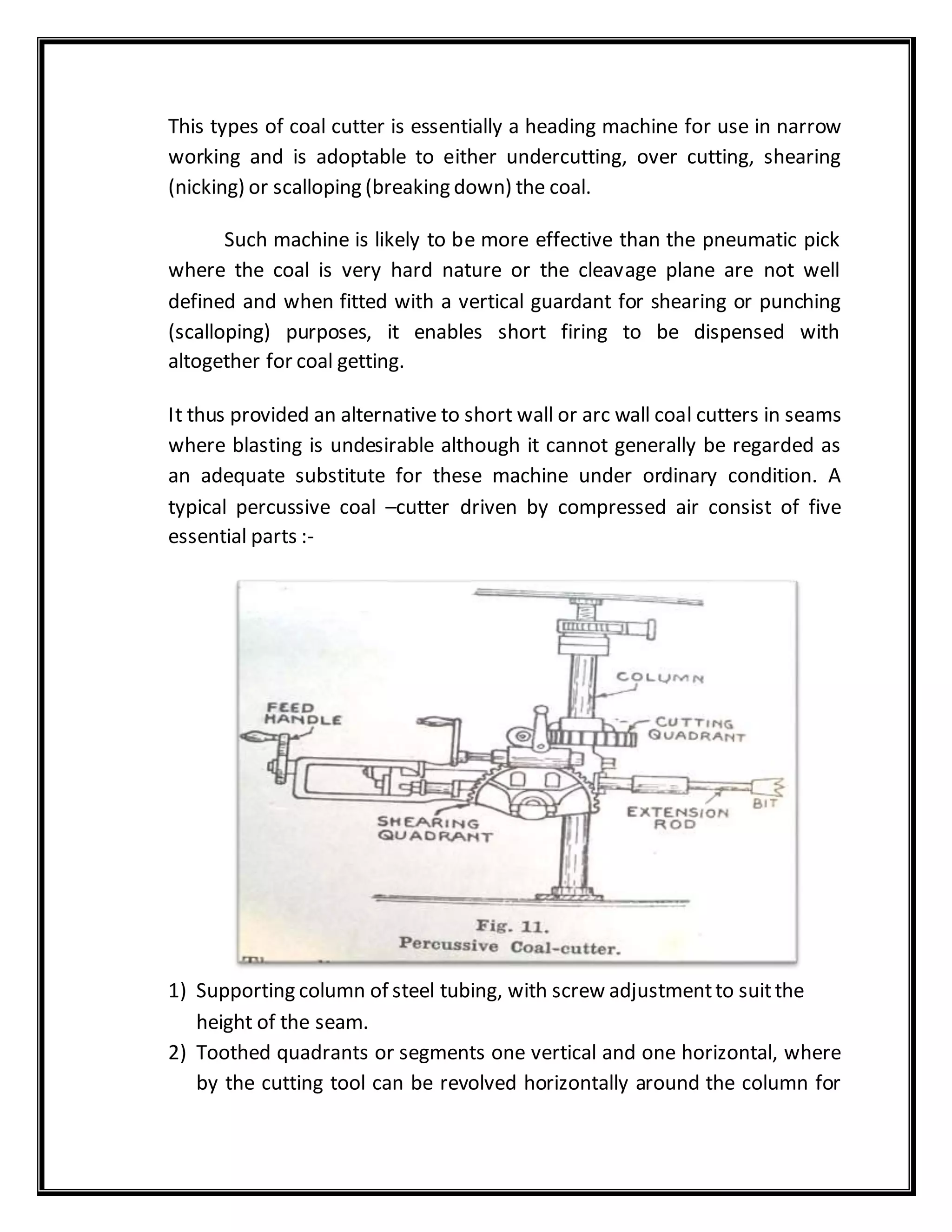
![CONTINUOUS MINER:
INTRODUCTIONOF CONTINUOUS MINER:
A continuous miner is a mining machine that produces a constant flow of
ore from the working face of the mine. The machine continuously extracts as
it is loading coal with a cutting steel drum and conveyor system. Continuous
miners are typically used in room and pillar mining operations. The
continuous miner is different from conventional or cyclical mining methods,
which halt the extraction process in order for ore-loading to proceed.[1]
Continuous miners, which began to take off in the mining industry in the
1940s, make up of 45 percent of the underground coalmine production.
Today, continuous miners are being developed as driverless machines s](https://image.slidesharecdn.com/compiled3year-190913072055/75/Mining-Machinery-Learning-Material-for-DEegree-and-Diploma-188-2048.jpg)

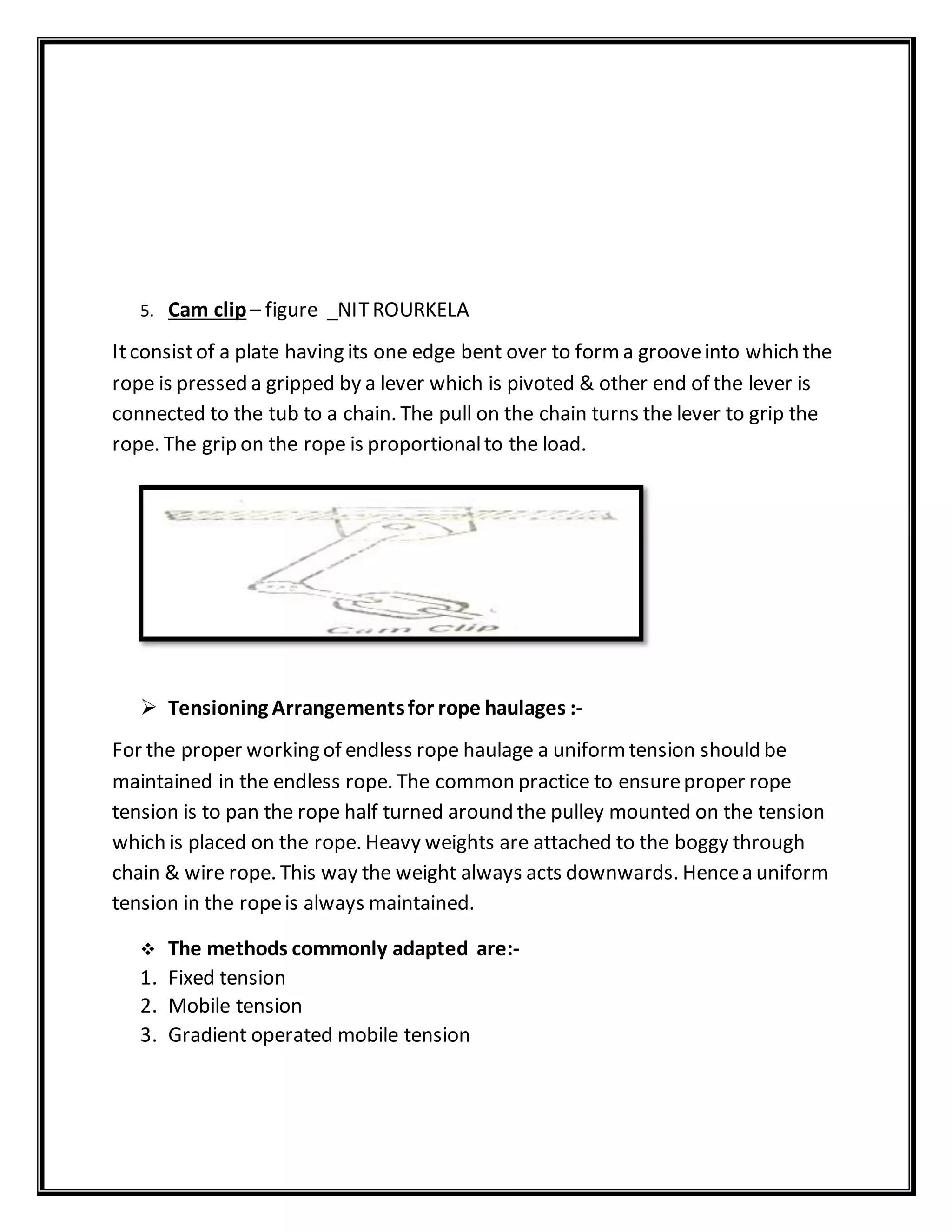
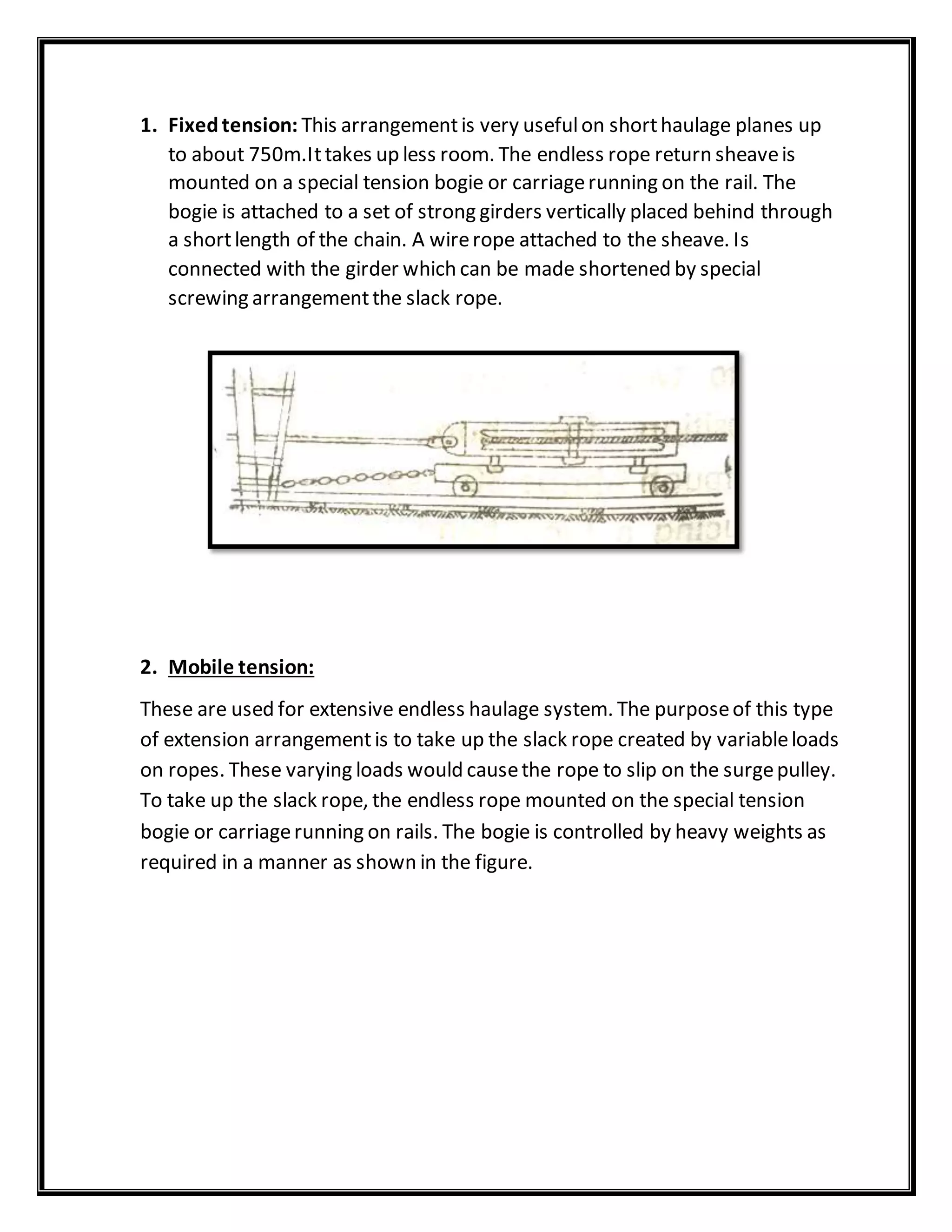
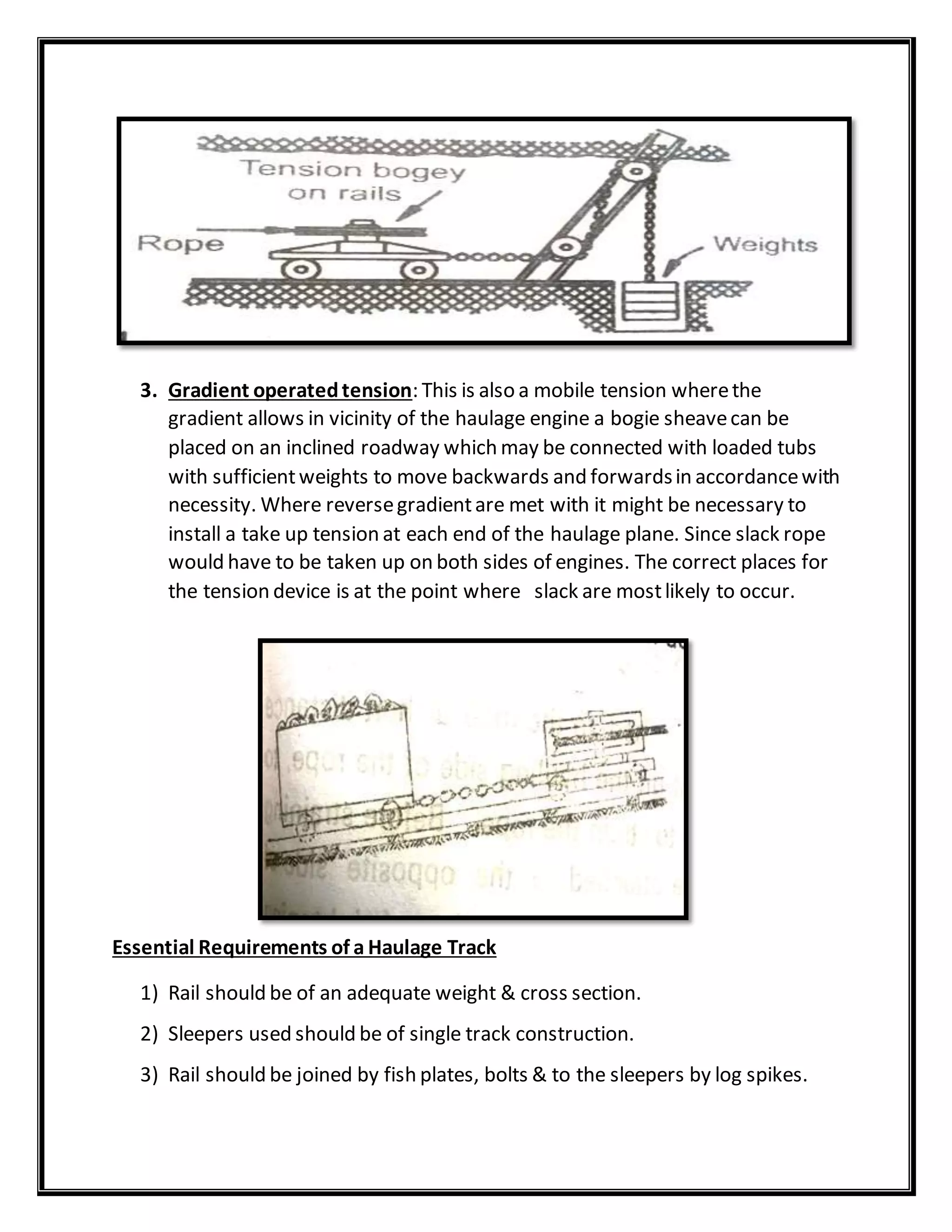
This document provides curriculum information for a mining and mine surveying course. It includes chapter summaries on topics like transport of ore, winding in shafts, wire ropes, mine pumps, coal cutting machines, and electric power supply in mines. Sample questions are provided for each chapter, covering areas like types of rope haulage systems, attachments used for endless rope haulage, power requirements for haulage systems, and safety devices. Diagrams illustrate components like driving pulleys, surge wheels, and rope clips used for haulage. Tensioning arrangements like fixed, mobile, and gradient operated systems are also summarized.