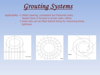
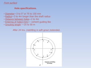
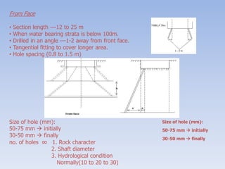
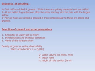
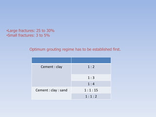
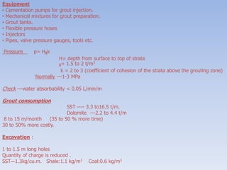
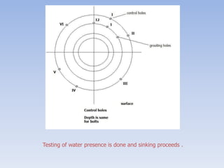
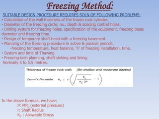
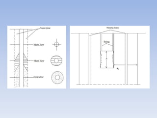
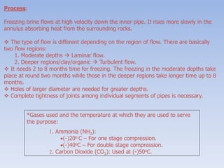
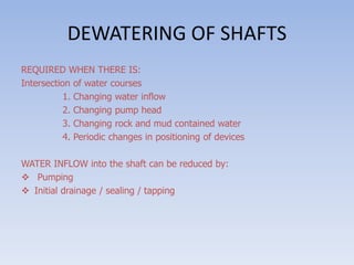
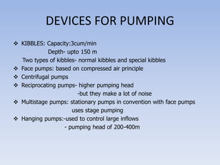
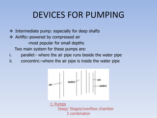
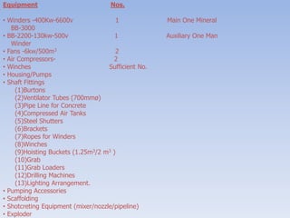
pipe one of the main article that is used in our daily life.its being manufactured and used in industries in large scale. because of its large application and uses they are being manufactured in varies levels and types
Mine Ventilation topic related to auxiliary ventilation. Only one type of auxiliary ventilation is discussed i.e., auxiliary fans and vent pipe because this method is more efficient as compared to other methods but method selection depends upon your problem and requirement means which method best suited to your needs.
TRUBORE offers the highest range of quality Agricultural Pipes & Fittings. TRUBORE is crafted to perfection with the highest rating of ISI with a wide range from 20mm to 250mm and working pressure mark and is available through a wide-spread network of around of 10kg/cm 2 , 6kg/cm 2 and 4kg/cm 2 as well as non-pressure 3500 dealers spread across the country. fittings.
Types of pipes and types of joints. Different types of pipes used for transporting water from reservoir or treatment plant for water supply in environmental engineering
Abstract Chimneys are very important structures for the emission of poisonous gases in power plants. After realising the urgent need to
restrict the pollution levels, chimney height is being rapidly increased. So most of the chimneys are tall slender structures which
fail due to wind excitation The present study discusses the dynamic behaviour of tall chimneys. Reinforced concrete chimney of
275m high, which is located in warora, Maharastra is taken for the present study. The objective of this project is to study the
change in the stress pattern due to presence of flue holes and also to carry out the influence of along wind and across wind effects
on the height of chimney for different wind speed and location. The analyse of chimney is carried out by developing a three
dimensional model created with plate elements using STADD Pro. The stress concentrations in the flue duct in the chimney have
been studied.
Keywords: Tall Slender, Warora, Maharastra, Flue Holes, STADD Pro, Stress Concentration
Analysis of Self Supported Steel Chimney as Per Indian StandardIJMER
Most of the Industrial chimneys are tall structures with circular cross-sections. Such slender,
lightly damped structures are prone to wind-exited vibration. Geometry of a self supporting steel
chimney plays an important role in its structural behaviour under lateral dynamic loading. This is
because geometry is primarily responsible for the stiffness parameters of the chimney. However, basic
dimensions of industrial self supporting self supporting steel chimney such as height, diameter at exit,
etc., are generally derived from the associated environmental conditions. Manholes are provided at the
bottom of the chimney for inspection purpose of the chimney. The presence of manhole reduces the
cross section area and hence the stiffness of the chimney. In the present study investigates the
stresses, deflection and mode shapes of the chimney due to the presence of an inspection manhole.
Maximum Von Mises stress, top deflection and mode shapes were calculated using finite element
software ANSYS. The results show that, the due to the presence of manhole, the stresses are increased
by approximately 1.5 times for the chimney and frequency is decreased by approximately 1.12 times
Within industry, piping is a system of pipes used to convey fluids (liquids and gases) from one location to another. The engineering discipline of piping design studies the efficient transport of fluid
Industrial process piping (and accompanying in-line components) can be manufactured from wood, fiberglass, glass, steel, aluminum, plastic, copper, and concrete. The in-line components, known as fittings, valves, and other devices, typically sense and control the pressure, flow rate and temperature of the transmitted fluid, and usually are included in the field of Piping Design (or Piping Engineering). Piping systems are documented in piping and instrumentation diagrams (P&IDs). If necessary, pipes can be cleaned by the tube cleaning process.
"Piping" sometimes refers to Piping Design, the detailed specification of the physical piping layout within a process plant or commercial building. In earlier days, this was sometimes called Drafting, Technical drawing, Engineering Drawing, and Design but is today commonly performed by Designers who have learned to use automated Computer Aided Drawing / Computer Aided Design (CAD) software
Every Step you need in planning to extend a working open cast mine to underground mine on reaching a pit bottom.
Step-wise procedure to be followed is clearly mentioned.
Justifies the Indian Laws.
Sublevel Stoping method is explained in detail.
Case study of a copper mine is presented for eg.
How to Create Map Views in the Odoo 17 ERPCeline George
The map views are useful for providing a geographical representation of data. They allow users to visualize and analyze the data in a more intuitive manner.
The Indian economy is classified into different sectors to simplify the analysis and understanding of economic activities. For Class 10, it's essential to grasp the sectors of the Indian economy, understand their characteristics, and recognize their importance. This guide will provide detailed notes on the Sectors of the Indian Economy Class 10, using specific long-tail keywords to enhance comprehension.
For more information, visit-www.vavaclasses.com
Ethnobotany and Ethnopharmacology:
Ethnobotany in herbal drug evaluation,
Impact of Ethnobotany in traditional medicine,
New development in herbals,
Bio-prospecting tools for drug discovery,
Role of Ethnopharmacology in drug evaluation,
Reverse Pharmacology.
Welcome to TechSoup New Member Orientation and Q&A (May 2024).pdfTechSoup
In this webinar you will learn how your organization can access TechSoup's wide variety of product discount and donation programs. From hardware to software, we'll give you a tour of the tools available to help your nonprofit with productivity, collaboration, financial management, donor tracking, security, and more.
The Roman Empire A Historical Colossus.pdfkaushalkr1407
The Roman Empire, a vast and enduring power, stands as one of history's most remarkable civilizations, leaving an indelible imprint on the world. It emerged from the Roman Republic, transitioning into an imperial powerhouse under the leadership of Augustus Caesar in 27 BCE. This transformation marked the beginning of an era defined by unprecedented territorial expansion, architectural marvels, and profound cultural influence.
The empire's roots lie in the city of Rome, founded, according to legend, by Romulus in 753 BCE. Over centuries, Rome evolved from a small settlement to a formidable republic, characterized by a complex political system with elected officials and checks on power. However, internal strife, class conflicts, and military ambitions paved the way for the end of the Republic. Julius Caesar’s dictatorship and subsequent assassination in 44 BCE created a power vacuum, leading to a civil war. Octavian, later Augustus, emerged victorious, heralding the Roman Empire’s birth.
Under Augustus, the empire experienced the Pax Romana, a 200-year period of relative peace and stability. Augustus reformed the military, established efficient administrative systems, and initiated grand construction projects. The empire's borders expanded, encompassing territories from Britain to Egypt and from Spain to the Euphrates. Roman legions, renowned for their discipline and engineering prowess, secured and maintained these vast territories, building roads, fortifications, and cities that facilitated control and integration.
The Roman Empire’s society was hierarchical, with a rigid class system. At the top were the patricians, wealthy elites who held significant political power. Below them were the plebeians, free citizens with limited political influence, and the vast numbers of slaves who formed the backbone of the economy. The family unit was central, governed by the paterfamilias, the male head who held absolute authority.
Culturally, the Romans were eclectic, absorbing and adapting elements from the civilizations they encountered, particularly the Greeks. Roman art, literature, and philosophy reflected this synthesis, creating a rich cultural tapestry. Latin, the Roman language, became the lingua franca of the Western world, influencing numerous modern languages.
Roman architecture and engineering achievements were monumental. They perfected the arch, vault, and dome, constructing enduring structures like the Colosseum, Pantheon, and aqueducts. These engineering marvels not only showcased Roman ingenuity but also served practical purposes, from public entertainment to water supply.
Model Attribute Check Company Auto PropertyCeline George
In Odoo, the multi-company feature allows you to manage multiple companies within a single Odoo database instance. Each company can have its own configurations while still sharing common resources such as products, customers, and suppliers.
The Art Pastor's Guide to Sabbath | Steve ThomasonSteve Thomason
What is the purpose of the Sabbath Law in the Torah. It is interesting to compare how the context of the law shifts from Exodus to Deuteronomy. Who gets to rest, and why?
How to Make a Field invisible in Odoo 17Celine George
It is possible to hide or invisible some fields in odoo. Commonly using “invisible” attribute in the field definition to invisible the fields. This slide will show how to make a field invisible in odoo 17.
This is a presentation by Dada Robert in a Your Skill Boost masterclass organised by the Excellence Foundation for South Sudan (EFSS) on Saturday, the 25th and Sunday, the 26th of May 2024.
He discussed the concept of quality improvement, emphasizing its applicability to various aspects of life, including personal, project, and program improvements. He defined quality as doing the right thing at the right time in the right way to achieve the best possible results and discussed the concept of the "gap" between what we know and what we do, and how this gap represents the areas we need to improve. He explained the scientific approach to quality improvement, which involves systematic performance analysis, testing and learning, and implementing change ideas. He also highlighted the importance of client focus and a team approach to quality improvement.
Palestine last event orientationfvgnh .pptxRaedMohamed3
An EFL lesson about the current events in Palestine. It is intended to be for intermediate students who wish to increase their listening skills through a short lesson in power point.
2. A PRESENTATION ON
GROUTING SYSTEMS
FREEZING METHODS
SHAFT DRILLING AND BORING
SHAFT SINKING
3. Grouting Systems
Applicability –1.Water bearing, competent but fractured rocks.
Sealed Zone is formed to arrest water reflow.
2.Voids also can be filled behind lining for improving lining
` tightness.
4. From surface
Hole specifications.
• Diameter—3 to 5” or 75 to 150 mm
• Radius—3 to 4m longer than the shaft radius
• Distance between holes—2 to 4m
• Entering of hole(3-5m)--- cement guiding like
• Grouting length ---25 to 50 m
After 24 hrs. /redrilling in soft grout /extended.
5. From Face
• Section length ---12 to 25 m
• When water bearing strata is below 100m.
• Drilled in an angle ---1-2 away from front face.
• Tangential fitting to cover longer area.
• Hole spacing (0.8 to 1.5 m)
Size of hole (mm):
50-75 mm initially
30-50 mm finally
no. of holes ∞ 1. Rock character
2. Shaft diameter
3. Hydrological condition
Normally(10 to 20 to 30)
Size of hole (mm):
50-75 mm initially
30-50 mm finally
6. Sequence of grouting: -
First half are drilled & grouted. While these are getting hardened rest are drilled.
All are drilled & grouted one after the other starting with the hole with the largest
inflow.
Pairs of holes are drilled & grouted & then perpendicular to these are drilled and
grouted.
Selection of cement and grout parameters
1. Character of water(salt or fresh)
2. Mineralisation and chemical corrosives
3. Value of the titration factor
Density of grout ∞ water absorbability
Water absorbability, q = Q/(Hh)
Q: water volume (in litres / min).
H: water need
h: height of hole section (in m).
7. •Large fractures: 25 to 30%
•Small fractures: 3 to 5%
Optimum grouting regime has to be established first.
Cement : clay 1 : 2
1 : 3
1 : 4
Cement : clay : sand 1 : 1 : 15
1 : 1 : 2
8. Equipment
• Cementation pumps for grout injection.
• Mechanical mixtures for grout preparation.
• Grout tanks.
• Flexible pressure hoses
• Injectors
• Pipes, valve pressure gauges, tools etc.
Pressure p= Hgk
H= depth from surface to top of strata
g= 1.5 to 2 t/m3
k = 2 to 3 (coefficient of cohesion of the strata above the grouting zone)
Normally ---1-3 MPa
Check ---water absorbability < 0.05 L/min/m
Grout consumption
SST ---- 3.3 to16.5 t/m.
Dolomite ---2.2 to 4.4 t/m
8 to 15 m/month (35 to 50 % more time)
30 to 50% more costly.
Excavation :
1 to 1.5 m long holes
Quantity of charge is reduced .
SST—1.3kg/cu.m. Shale:1.1 kg/m3 Coal:0.6 kg/m3
10. Freezing Method:
SUITABLE DESIGN PROCEDURE REQUIRES SOLN OF FOLLOWING PROBLEMS:
• Calculation of the wall thickness of the frozen rock cylinder.
• Diameter of the freezing circle, no., depth & spacing control holes.
• Drilling system for freezing holes, specification of the equipment, freezing pipes
diameter and freezing time.
• Design of temporary shaft head with a freezing basement.
• Planning of the freezing procedure in active & passive periods.
-freezing temperature, heat balance, ‘h’ of freezing installation, time.
• System and time of Thawing.
• Freezing tech planning, shaft sinking and lining.
Normally 5 to 5.5 metres.
In the above formula, we have:
P: MPC (external pressure)
r: Shaft Radius
KC : Allowable Stress
11.
12. Freezing Holes
Thickness of frozen cylinder: 5 to 5.5 m.
(Where, H: Depth up to shaft bottom.)
• Dm is larger by 2 m to the shaft. (80m)
• Dm is larger by 2.5 m to the shaft. (150m)
• Dm is larger by 3 m to the shaft. (>150m)
13. Distance between freezing holes – 0.9 to 1.1m. More 1.25 for deep.
The chord of overlapping circles should be equal to the calculated thickness of
frozen wall.
Depth of holes 5m below water bearing strata (55m).
Verticality of holes is the biggest problem.(Additional holes may be required)
2 to 3 rigs / mud fluid drilling medium /
Freezing hole equipment:
There are two columns of tubing –
1. Outside: 102 to 152m.
2. Inside : 32 to 51mm (steel) or (polyethylene)*
* Polyethylene has an advantage over steel because:
• It has a lower weight.
• It is cheaper.
• It is easier to install.
• It has a lower thermal conductivity.
• Specific gravity is same as the brine.
We hence prefer polyethylene more over steel for the tubing purpose.
14. Process:
Freezing brine flows at high velocity down the inner pipe. It rises more slowly in the
annulus absorbing heat from the surrounding rocks.
The type of flow is different depending on the region of flow. There are basically
two flow regions:
1. Moderate depths Laminar flow.
2. Deeper regions/clay/organic Turbulent flow.
It needs 2 to 8 months time for freezing. The freezing in the moderate depths take
place at round two months while those in the deeper regions take longer time up to 8
months.
Holes of larger diameter are needed for greater depths.
Complete tightness of joints among individual segments of pipes is necessary.
*Gases used and the temperature at which they are used to serve
the purpose:
1. Ammonia (NH3):
(-)20o C – For one stage compression.
(-)40oC – For double stage compression.
2. Carbon Dioxide (CO2): Used at (-)50oC.
15. Periods:
oActive: - 3 units min. full capacity till the desired frozen cylinder forms.
oPassive: - Maintaining frozen rock mass at desired temperature during sinking &
lining. 1/2 to 1/3 times the capacity is sufficient.
Heat Losses:
Heat from outside the frozen material.
Losses in freezing installation due to imperfect insulation.
Frost Penetration Velocity: -
The penetration occurs at the rate of: (i) 25mm per day in sand.
(ii) 10-15mm per day in clay.
On a larger scale, the penetration rate is: (i) 2-4 months per 250 metres of depth
(ii) 9-10 months per 500 metres of depth
16. EQUIPMENT FOR SHAFT SINKING
(A)Site preparation
above HFL(100 years record)
1. Construction of roads and material storage areas
2. Grading of the terrain(while sinking also this can be done)
3. Water supply(drinking, industrial use and fire extinguishing)
80 - 120m3 / day 40 - 60m3 / day 80-100m3 / day
plant water tap water fire tank
( adequate ditch for storm water )
4. Electrical power supply(2 stages)
Preparatory - 260 KVA transformers - Diesel generator stand bye
Sinking - 1200 KVA, 500 V - Diesel generator stand bye
5. REQUIREMENTS:-
Storage space for material
Ramp for unloading heavy machinery
Telephone lines
Temperature buildings and head gear foundation
Installation of sinking equipment
Surveying of shaft elevation, centering
17. (B) Temporary Buildings
1. Office, first aid room, heating and cooling units, ware house
2. Lamp house(in accordance with MSHA standards)
3. Mechanical and blacksmith shop(for minor repair work)
4. Compressor sheds
5. Transformer station
6. Shed for concreting, mucking and other equipment
7. Shed for cement storage
8. Winch building for shaft stage
9. Fan housing
10.Flammable supplies ware house
11.Hoist Buildings
12.Storage for explosives(Magazine)
13.Accommodation for sinking crew.
18. 1) SHAFT COLLAR CONSTRUCTION(8-12m)
• Air Channel
• Channel for water pipes, air pipes
• Ladder Compartment
• Basement for pushers
2) D & B in Shafts : supposed to ensure-
(a) Correct size and shape of planned excavation
(b) Even shape of the surface
(c) Uniform size of broken rock
(d) Safe and economical operation
3) Mucking Shaft :- 50- 60% of cycle time
Mucking ‘η’
Depth
19. Muckers
Several type of muckers are in use depending on-
Shaft shape, size, depth and location
1. Scrapers- rectangular shafts
large dia shafts (U/G bunkers)
2. Overshot loaders on caterpillars
3. Cryderman Muckers
4. Cactus Grab (light)
5. Cactus Grab (heavy) Central Pivot (1.3cu)
Hanging from platform/hand guided
Attached to shaft wall(3)type
Large cap muckers for deep min/larger dia
- electric, pneumatic or hydraulic
Capacity:-
Pt= 3600 k Vb / t
where
Pt = Thermal Capacity in cubic meter per hour
k = Fill factor (0.8 to 0.9-sandstone
1.1 to 1.2-shale)
Vb = Bucket Capacity in cubic meter
t = mucking time
Lowering
Templing
Cleaning
20. DEWATERING OF SHAFTS
REQUIRED WHEN THERE IS:
Intersection of water courses
1. Changing water inflow
2. Changing pump head
3. Changing rock and mud contained water
4. Periodic changes in positioning of devices
WATER INFLOW into the shaft can be reduced by:
Pumping
Initial drainage / sealing / tapping
21. DEVICES FOR PUMPING
KIBBLES: Capacity:3cum/min
Depth- upto 150 m
Two types of kibbles- normal kibbles and special kibbles
Face pumps: based on compressed air principle
Centrifugal pumps
Reciprocating pumps- higher pumping head
-but they make a lot of noise
Multistage pumps: stationary pumps in convention with face pumps
uses stage pumping
Hanging pumps:-used to control large inflows
- pumping head of 200-400m
22. DEVICES FOR PUMPING
Intermediate pump: especially for deep shafts
Airlifts:-powered by compressed air
-most popular for small depths
Two main system for these pumps are:
i. parallel:- where the air pipe runs beside the water pipe
ii. concentric:-where the air pipe is inside the water pipe
t. Pumps
Deep/ Stages/overflow chamber
3 combinaton
23. Equipment Nos.
• Winders -400Kw-6600v 1 Main One Mineral
BB-3000
• BB-2200-130kw-500v 1 Auxiliary One Man
Winder
• Fans -6kw/500m3 2
• Air Compressors- 2
• Winches Sufficient No.
• Housing/Pumps
• Shaft Fittings
(1)Burtons
(2)Ventilator Tubes (700mmø)
(3)Pipe Line for Concrete
(4)Compressed Air Tanks
(5)Steel Shutters
(6)Brackets
(7)Ropes for Winders
(8)Winches
(9)Hoisting Buckets (1.25m3/2 m3 )
(10)Grab
(11)Grab Loaders
(12)Drilling Machines
(13)Lighting Arrangement.
• Pumping Accessories
• Scaffolding
• Shotcreting Equipment (mixer/nozzle/pipeline)
• Exploder
24. Purpose
1) Production 2) Service 3) Ventilation 4) Exploration
5) Escape 6) Combination
Brakes:
Holding of hoist drum
Electrical (mechanical breaking system )
(Normal/emergency operation)
Electric breaking
1. Regenerative energy returned to system / induction generator developer
2. Breaking torque
3. Counter torque
4. Dynamic
Mechanical breaking
1. To slow down the drum
2. Holds the drum at rest
Jaw /parallel motion /disk brakes –friction hoists
Drum /friction hoists
Calliper brakes
1. Speed /force of breaks
2. Controlled by oil flow
25. Drum hoist
1. Over wind /rope breakage
2. Safety dog
Friction hoist
Over wind: Arrestor Gear
26. Ventilation
Ducting is hung in the shaft by two steel ropes connected periodically to collars
round the pipe.
Lights
-safety
-output
-flood light charters
-suspended stage and tensor frame special reflector and sealed cover
-hang on ropes(special cable)
-100W lamps and even 40-50m of water.
27.
28. SHAFT DRILLING AND BORING
Boring of shafts/large diameter holes/ foundation of off-shore drilling.
Shaft sinking is slow, tedious, hazardous and uncomfortable.
Drilling is possible up to depths 1000m.
Diameter - 10m
Weak and moderate - Strength rock (300MPC)
Cope with difficult hydro geological conditions.
STEPS IN DESIGNING
Geotechnical and hydro geological parameters.
Planned shaft diameter, depth, adequate cutters for the type of rock, stages of reams
and properties of drilling fluid.
Design of shaft head.
Living placement methodology/sealing.
Sealing of water.
Organization of the drilling site, location of ponds, storage of living components.
DRILLING FLUID
Water and natural clay / SG - 1.15 to 1.25
29. DRILLING EQUIPMENT
Drilling equipment consists of Heavy drill rigs having sufficient capacity to provide the
required torque and the hoisting capacity.
Ex: - CSD 300 (Hughes Micon)
6 Hydraulic motors, 70 KNm Torque
Shaft Alignment is 1 in 1000
CUTTERS
• Milled steel tooth cutters - Soft rock
• Tungsten carbide cutters - harder rock (abrasive)
• Disk cutters - not needed for (blind hole drilling)
LINING
200mm/ Shot Crete / Bolts / Wire mesh/ concrete/prepared and placed.
30. SHAFT BORING
• New / least matured (1960’s)
• SBM’s (vertical TBM’s)(personnel travel log inboard)
• Picking up the cutting is the major problem.
• Wirth m/c - successful with pilot hole for free much removal to a lower face.
• Blind shafts were driven with limited success only.
• SBM’s (2cutter motors of 261 KW / disc cutters)
• Carboniferous rock is the most suited one.
• Grouting of water bearing strata is mandatory before shaft boring.
SHAFT RAISING
• Raise boring m/c’s in place of conventional methods are common today
• Raise climbers
• Lower level is developed
• When sinking is not possible due to lack of space or lack of room for production
• Only on competent rocks
• Without water inflow
31. ADVANTAGES
Influence on mine performance is minimum
Loading of muck into buckets is avoided
Blasting efficiency is greater
No water pumping is required
DISADVANTAGES
Height of rising limited (100 to 120m)
Ladder climbing inconvenient for men and material transport.
Potential hazard of pieces of rock falling from face
Potential threat of much jamming on chute
Surveying is difficult
Time and cost for preparing the opening for raising purpose.
32. EQUIPMENT
Chute
Hoist
Ladder
Brattice
Heavy load bearing wooden platform with steel girders
F.O.S - 6
Face to platform 1.5m-3.0m, 5m(at a go) (in strong rocks)
Ventilation through a (200 - 300m) diameter hole drilled above.
ALTERNATIVES (3)
Raising the diameter up to 4m(Temperature/permanent)
Permanent lining is done at every short interval.
Diameter > 4m. Pilot hole is then widened.
33. MECHANICAL RAISE CLIMBERS:
For hard rock (Alimah- Swedish)
Runs on a guide rail (Pin rock) (through rock bolts)
ADVANTAGES:
Permits the driving of very long raises, vertical or inclined, straight or curved.
When travelling to the head of the raise, personnel are well protected in a cage under
the platform.
Miners work on a platform whose height/angles can be adjusted.
Risks of gases are reduced(through ventilation)
All the material can be transported easily.
Timbering avoided / rock bolting and mesh may be used.
Usable up to 8m2 area.
DISADVANTAGES:
Cost for short stretches not justified.