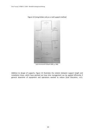
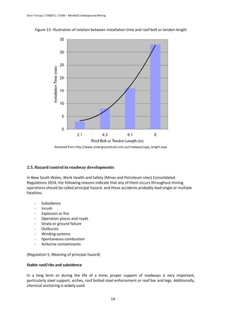
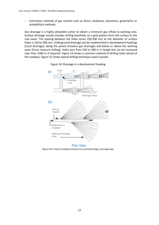
SlideShare a Scribd company logo
Onur Tuncay / 5706671 / UOW – Mine920 Underground Mining
1
ASSIGNMENT A: UNDERGROUND COAL MINING
All drawings must be presented in a clear and professional manner. Relevant
reference must be provided.
1) For a coal seam of 2~5 m thickness, 5-100
dip and an overburden of 350-
500m with competent floor and roof and moderate geological structures, select
and describe the main means of accessing this coal seam, identify and discuss
factors need to be considered in selecting the appropriate means of access, use
neat diagrams for your description and discussion. (1500 words, 25 marks)
2) With the aid of neat diagrams, describe gateroads development process, the
main equipment used and their main functions; Discuss briefly roadway support
system and hazards control associated with roadway development (1000 words,
25 marks)
3) With the aid of neat diagrams, describe and compare different longwall
mining system (advance and retreat), identify and discuss briefly the main
hazards and problems associated with longwall mining and their solutions. (800
words, 25 marks)
4) With the aid of neat diagrams, describe different thick seam mining methods.
(1000 words, 25 marks)
REFERENCES ARE NOT IN PROPER SHAPE
THAT HAS TO BE.
Onur Tuncay / 5706671 / UOW – Mine920 Underground Mining
2
1. Mine access operations
1.1. Mining access types
Operations based on underground coal mining used all conventional means of seam access, such as:
- Adit,
- Shaft, mostly vertical shaft,
- Cross measure drift, decline or inclined shaft.
In New South Wales (NSW), the required limits of installing shaft needs to be considered at least two
roadways to apply separation for men and materials haulage, and ventilation if coal is transported
from underground to the surface by conveyor.
Some methods have been used for inclined mine access in New South Wales such as:
- Two shafts: Upcast designed for bulk coal winding, downcast transportation for men and
materials,
- Two shafts: Upcast for bulk coal haulage, downcast for ventilation only. One drift for men
and materials transport.
- Two shafts: Upcast for ventilation, downcast for men and materials. One drift for
transportation of coal by conveyor.
- Two shafts: Both of upcast and downcast for ventilation. Conveyor drift for coal
transportation, other one material and men transport with intake of clean air.
The capital costs for shaft sinking have increased in recent years. Therefore, one of the effective ways
of accessing underground deposit is cross measure drift. A nearly horizontal passages, adits, they
ensure fast transportation to coal seam by diesel based vehicles or conveyor belts carrying mining
equipment, The criteria for selecting the most suitable method of transporting and accessing an
underground mine depends on many variables. The variables involve:
- Coal clearance,
- Ventilation,
- Surface topography,
- Height of overburden,
- Environmental effects,
- Geotechnical and geological features,
- Personnel and equipment access,
- Mine closure,
- Capital operating costs,
(eds Kininmonth & Baafi 2009, p. 176).
Onur Tuncay / 5706671 / UOW – Mine920 Underground Mining
3
1.2. Portal construction
There are two basic alternative designs for portal construction for using as a cross measure drift:
- Excavation of open approach cut is applied until reaching to construct collars which probably
place in far away from competent ground after that reinforced concrete arch is
implemented to continue drift.
- This approach for excavation can be kept constructing same way until reaching competent
ground then next procedure is followed such: covering open cut section, installing metal
culvert liners and backfilling.
(eds Kininmonth & Baafi 2009, p. 189).
1.3. Driving of adits
Drift features
As the maximum angle of inclination on which materials can be conveyed on standards conveyors is
about 160
, belt drifts are driven at the angle to ensure minimum length. This angle is within the limit
where winding engine drivers are not required and is such that breaking devices on rolling stock can
bring them to a standstill in the event of a runaway. Thus 160
angle of inclination is virtually
universally adopted for major access of openings (eds Kininmonth & Baafi 2009, p. 187).
In this sample mine, as required minimum inclination, cross measure drift or inclined shaft with 100
can be selected, accordingly, the slope of the two main headings can be operated with 400/sin100
=
2304 meter as it can be calculated from the basic geometry formula (overburden is 400 m). In the
light of fundamental laws of mining, access of mine should be operated with minimum two shafts
(inclined) lying from the surface to underground, parallel to each other.
Used equipment’s in drifting
Eventually, a fairly wide range of sinking plant has been used for the driving of cross measure drifts,
depending on the method adopted. Among the combinations which have been used are:
- Drilling and blasting, slusher winch – skip system
- Road header machine for mucking and rock breaking – skip system
As a most suitable method for drifting, drilling and blasting techniques or road header machines are
the most worth to use, nevertheless drill and blast is conversely the most wide used technique for
drifting. After blasting, broken rock is continuously loaded and transported from excavated area to
the surface in a rail skip with pulling by wind system. Another approach to haulage, pickling made by
blasting operations can be transported by trucks carrying the waste from the face by the help of
loaders (eds Kininmonth & Baafi 2009, p. 189).
In the Table 1, by means of recent experiences in mite sites, for under 15 MPa vertical stresses, many
combination of development effected by roadway dimensions can be seen as a unit per week.
Onur Tuncay / 5706671 / UOW – Mine920 Underground Mining
4
Varying mining heights and longwall block lengths, typically for super unit mines – at least two
continuous miners, are shown in the table for 300 m coal face wide.
Table 1: Effects of Roadway dimensions to the development rates
Note: Date from Australian Roadway Development-Current Practices Final Report (2005)
http://www.undergroundcoal.com.au/roadway/workshops/C15005FinalReport.pdf
Supporting
Ground stresses are commonly doubled by mining operations, in a result of exceeding present
support or reinforcement elements. Particularly overburden with 400 m is quite equal to 1000 t/m2
(10MPa) vertical stress. The vertical stress formula is seen below:
Vertical Stress (MPa) = height of overburden (m) x 0.025
Additionally, Roadway excavated less than angle of 200
shows that it is one of the best variance of
roof conditions, faster development rates and greatest stability features. Otherwise, in the slopes
more than angle of 200
will be highly monitored the major horizontal stress which may lead roof
failure.
Wide usage of reinforcement for roof is rock bolts for primary installations in inclined shafts. Then
cable bolts is installed to extend above present bolts and increase roof stability conditions. Another
method to increase the rock strength and prevent counter fracturing of rock, is injection of chemical
bonding agents such as Polyurethene into the rock (eds Kininmonth & Baafi 2009, p. 279).
Onur Tuncay / 5706671 / UOW – Mine920 Underground Mining
5
2. Underground operations
2.1. Bord and pillar
The basic understanding of bord and pillar method involves application of dividing the coal seam
into regular or particular blocks with array by excavating main headings, which are intersected at
regular intervals by bonding cut-throughs. The blocks of coal are fully surrounded, or nearly, by
roads are called as “pillars”. The pillars ensure a support to overcome extreme load of
overburden during “first workings”, also called as development process. Actually, in Australia, for
long years, room and pillar method has been the main underground mining method for the
medium-thick seams (eds Kininmonth & Baafi 2009, p. 297).
Figure shows a seven-heading bord and pillar underground development and equipment related
to operation.
Figure 1: Plan view of room and pillar section with the assistant equipment
Illustration received from http://www.scielo.org.za/scielo.php?script=sci_arttext&pid=S2225-62532012001000003
Onur Tuncay / 5706671 / UOW – Mine920 Underground Mining
6
Barrier pillars
Barier pillars are longer natural solid structures rather than their width, and applied for separation of
panels or isolation of sealed areas. They must handle required multifunctional tasks:
- To overcome giant abutment loads placing around working areas as result of driving panels,
- To obtain optimisation of panel dimensions; especially width, which prevent unwanted
occasions by naturally supporting roof conditions in roadways and particular zones.
- By means of sufficient width and stability of panels, isolate working areas against gas
leakage or inrush (eds Kininmonth & Baafi 2009, p. 257).
Chain pillars
In Underground coal mining, particularly in longwall operations, chain pillars play an important role,
such barrier pillars, to reduce roof stress, or encounter the many stress components imposed to the
working place, even if the goaf produced, they can ensure subsidence control. Primary task of
driving chain pillars is to reduce abutment stresses possibly affecting the load over the barrier pillars,
cut throughs and main headings. Other types of pillars such as production or yield pillars are rarely
used just in case (eds Kininmonth & Baafi 2009, p. 257).
2.2. Development work
First workings, also called as development work, is driving for creating infrastructural ways to employ
operation equipment - such as shuttle cars, trailing cables, bolters, conveyor or continuous miners- in
main headings and cut-throughs by dividing the untouched coal seam to be operated into the certain
pillars at interval. Development works are operated the following purposes:
- To maintain multiple roads supported by pillar in a long term for accessing coal deposit,
- To obtain appropriate conditions for excavating pillars in the end of operations,
As required logical aspects, it is clear to mention that longer pillars provide less development process
and less number of panels to be excavated. During development, the process at the face includes
different three tasks. To reduce downtime of equipment placed in a cycle such delays in installing
roof supports, among shuttle cars or other infrastructural services as much as possible. (eds
Kininmonth & Baafi 2009, p. 312).
Onur Tuncay / 5706671 / UOW – Mine920 Underground Mining
7
Figure 2: Sample positions for electrical cables and face equipment in room & pillar
(eds Kininmonth & Baafi 2009, p. 300)
2.3. Used equipment in development process
The list of increasing usage of equipment in development stage can be seen as follow:
- Continuous Miners
- Shuttle Cars
- Feeder-Breaker Units
- Conveyer Belts
- Bolters
Continuous miners
Continuous miners are considered as suitable for first workings due to allowing single passing, and
they also widely use extendable belt conveyors to haul extracted coal after removed the seam.
Remote controlled ones are initiated to work in various challenging coal seams and some of them
became quite popular which ones can be driven by computers. Within in 1 m of the face, many of
them are capable of installing support with their roofbolting mechanism with ring and two rib
Onur Tuncay / 5706671 / UOW – Mine920 Underground Mining
8
bolters. However the main required task of CM should be to mine coal from the face and load it to
the conveyor at no interval because in some weak seams, early enforcement for roof should be
applied rapidly. Therefore, innovative continuous miners instead of conventional ones are not only
quite suitable to bolt and enforce the roof at the same time but they also are very productive
without downtime (Coal Education, n.d.)
Developed characteristics of the most innovative continuous miners involve the following:
- Allowing remote control by displaying in monitor visually
- Wider throat of chain conveyor allows shuttle cars to haul coal quickly
- Data logging of used machines can be applied on board
- Roof and rib bolters on board (eds Kininmonth & Baafi 2009, p. 300).
Figure 3: JOY 12ED30 Series, Single Pass Miners/Bolters with capable of excavating, drilling and
bolting in same machine
Data received from Komatsu official website, https://mining.komatsu/underground-mining/room-pillar-entry-
development#!entry-drivers
Figure 4: Conventional continuous miners, series of JOY 14CM15 and JOY 14CM10 respectively
Data received from http://www.coaleducation.org/technology/Underground/images/Joy_Mining/14CM15.jpg -
http://www.coaleducation.org/technology/Underground/images/Joy_Mining/14CM10.jpg
Onur Tuncay / 5706671 / UOW – Mine920 Underground Mining
9
Shuttle cars
The most used shuttle cars in Australia can be seen in Figure 5.
Figure 5: JOY shuttle cars
Data received from https://mining.komatsu/product-details/shuttle-cars
The shuttle cars allow loading the coal mined by continuous miners in the development face and
transporting from the face to feeder breaker unit. Their main power engines are based on
electricity generated by alternative currency with a trailing cable. With 4 – 20 ton capacity of
payload, they have various types of shuttle cars which each one can be used in different working
conditions due to varying height and width of the roadways. Operation boundaries unfortunately
depend on length of trailing cable which is, allowing around 150 m.
Feeder-breaker units
As can be understood from its name, these beneficial machines allow the loaded coal on it both of
breaking and feeding. Broken coal already mixed with water in the unit is fed to conveyor belt
directly. If coal is not fed on the conveyor belt properly, many obstacles for operation occur
because of frequently faced the case of high ratio of blocky lumps causing damages in conveyor
system, tracking problems, and conveyor belt spillage. By means of feeder breaker unit, mined
coal can be transported with uniform and oversized pieces. It can be seen in Figure 6.
Figure 6: Feeder-Breaker Unit
Data received from Komatsu official website: https://mining.komatsu/product-details/ufb-33
Onur Tuncay / 5706671 / UOW – Mine920 Underground Mining
10
Extendable Conveyors
This type of conveyors are lying throughout from end of the panel operations underground to
passing entire roadways, then to the surface. Its sample position was shown in Figure 2.
Additionally, extendable conveyors certainly maintain continuous activity by hauling the coal from
continuous miners to the feeder breaker unit rather than shuttle cars do. They are considered the
most common alternative haulage system, which are being now applied in many underground coal
mines by using chain haulage systems and flexible conveyor train, which is seen in Figure 7.
Figure 7: Chain haulage systems and flexible conveyor train respectively
Data received from Komatsu official website: https://mining.komatsu/docs/default-source/product-
documents/underground/room-and-pillar-entry-development/rsa-hs01-1114-v1.pdf?sfvrsn=38
Bolters
Roof bolters are necessarily used in underground coal mines to stabilise roof conditions and
ensure more secure working conditions for workers, by drilling bore holes and installing rock bolts.
These machines are able to drill with four-hand bolters -also two-hand or single hand bolters exist-
operation length varying from 1.8 m to 6 m as can be seen in Figure 8.
Figure 8: Several views of a sample Quadbolter.
Data from: https://mining.komatsu/docs/default-source/product-documents/underground/room-and-pillar-entry-
development/bolting-products-brochure---rb04-0712.pdf?sfvrsn=34
Onur Tuncay / 5706671 / UOW – Mine920 Underground Mining
11
Figure 9: Loader
Data received from https://mining.komatsu/docs/default-source/product-documents/underground/room-and-pillar-
entry-development/en-14bu27l01_loader-brochure.pdf?sfvrsn=42
2.4. Roadway support systems
Rib support with fibreglass dowels and steel roof bolting techniques are commonly applied in main
headings. The rock bolts are generally installed through steel mesh or light steel straps combined
with shotcrete. The most common usage of bolt length is 1.8 m, of course, its lengths depends on
many parameters, particularly roof strata, otherwise longer or shorter at length bolts are also in
use. In Australia, main headings are driven with maximum 5.5 m wide and around 3.5 m height,
and pillar dimensions 50 x 50 m, which these are considered a suitable working environment to dip
up to 600 m. Figures 10, 11 and 12 show typical roof support techniques in many mines to give a
sample design (eds Kininmonth & Baafi 2009, p.307).
Onur Tuncay / 5706671 / UOW – Mine920 Underground Mining
12
Figure 10: Using straps, props and bolts
(eds Kininmonth & Baafi 2009, p. 308)
Figure 11: Using props, bolts, rail bars and straps
Received from (eds Kininmonth & Baafi 2009, p. 309)
Onur Tuncay / 5706671 / UOW – Mine920 Underground Mining
13
Figure 12 Using timber only as a roof support method
(eds Kininmonth & Baafi 2009, p. 308).
Addition to design of supports, Figure 13 illustrates the relation between support length and
installation times, which have pointed out how time management can be applied efficiently if
general downtime of equipment and operations wanted to reduce (Coal Education, n.d.).
Onur Tuncay / 5706671 / UOW – Mine920 Underground Mining
14
Figure 13: Illustration of relation between installation time and roof bolt or tendon length
Received from http://www.undergroundcoal.com.au/roadway/supp_length.aspx
2.5. Hazard control in roadway developments
In New South Wales, Work Health and Safety (Mines and Petroleum sites) Consolidated
Regulations 2014, the following reasons indicate that any of them occurs throughout mining
operations should be called principal hazard, and these accidents probably lead single or multiple
fatalities.
- Subsidence
- Inrush
- Explosion or fire
- Operation places and roads
- Strata or ground failure
- Outbursts
- Winding systems
- Spontaneous combustion
- Airborne contaminants
(Regulation 5, Meaning of principal hazard)
Stable roof/ribs and subsidence
In a long term or during the life of a mine, proper support of roadways is very important,
particularly steel support, arches, roof bolted steel enforcement or roof bar and legs. Additionally,
chemical anchoring is widely used.
Onur Tuncay / 5706671 / UOW – Mine920 Underground Mining
15
Roadways which will be required for a major part of the life of a mine are, in many cases,
supported on some form of steel support, be it roof bar and legs, roof bolted steel members or
arches. Roof bolts utilising split and wedge, and chemical anchoring are employed.
Techniques used to provide protection from slabbing ribs include:
- Simple lagging,
- Steel roof bolts with plates or pads,
- Fibreglass dowels with or without plates,
- Steel wire mesh covered by bolts, dowels or sprags,
- Steel straps covered by bolts or dowels,
- Fibreglass mesh covered by bolts or dowels.
(eds Kininmonth & Baafi 2009, p. 513).
In final report of ACARP, many mines in this research applied a variation of 2 rib bolting rigs and 4
roof bolting rigs. Roof bolts also are installed varying from 1.8m to 2.4m in length, each in 1.5
meter four 1.8m bolts to eight 2.4m bolts in every meter, last but not least, 2.1m bolts in every
meter (41% of the reported mines).
32% of the mines stated that 4m or 6m tendons are applied for primary workings, routine basis or
required implementation of 13 different supports result of strata management and trigger levels.
Other implementations in roof support as following:
- Length of rib bolts vary between 1,2m – 1.8 m.
- Interval of intensity is one-1.2m bolt/rib/m and one to three 1.2 m, two 1.5m, or two 1.8
bolt/rib/m
Final report also states that companies participating research were implementing three bolts with
full rib meshing for each cycle per rib. (Underground Coal Website, n.d.)
Inrush
In the light of previous experience of miners and reported incidents, Table 2 shows some of these
cases as a distribution of accident sources. Primary causes of accidents can be stated that:
- Insufficient barriers
- Inefficient mine planning
- Inefficient protective boreholes
-
Table 2: Common sources of water incidents
Source of Water Number of Incidents
Contact with surface water 9
Contact with surface unconsolidated deposits 8
Onur Tuncay / 5706671 / UOW – Mine920 Underground Mining
16
Strata water entering workings 2
Shaft Sinking 4
Clearing old shafts 14
Contact with abandoned old workings 162
Failure of an underground dam 9
(eds Kininmonth & Baafi 2009, p.793)
In a nutshell, surveying and investigating of rock strata of the mine site should be carefully
controlled and checked counter possible water inflow. The underground water that leaks to the
mine must be stored to use it in order to reduce dust rate over the air. (eds Kininmonth & Baafi
2009, p.781)
Outburst
In coal mining, it has been described as an instant gas burst of coal, expect rock burst. Where the gas
mixed with carbon dioxide and methane causing many accidents has several primary reasons:
- Depth of mining
- Mining operations
- Faults and folds
- Seam thickness
- Gas content and its environment
- Strength of the coal seam
- Rank of coal seam
- Permeability
- Volumetric change
- Cleats and joints
Outburst management needs analytical and frequently controlled approaches, to predict and
prevent possible incidents before happen. There are wide applications for prediction of,
prevention against, and control of outburst in mine sites:
Prediction methods:
- Seams having complex geological structures are more prone to outbursts if high gas
conditions are prevalent.
- Gas monitoring systems such as Tube Bundel System or Telemetry System.
- Seismic reflection surveying
- Logging in seams boreholes
- Detection of igneous intrusions
- Detection of zones poorly drained of gas
- Radio imaging method (RIM)
- Monitoring for outburst precursors
- Estimating Gas Threshold Values (GTV)
Onur Tuncay / 5706671 / UOW – Mine920 Underground Mining
17
- Estimation methods of gas content such as direct, analytical, volumetric, gravimetric or
probabilistic methods.
Gas drainage is a highly adoptable action to obtain a minimum gas inflow to working area.
Surface drainage mostly includes drilling boreholes on a grid pattern form the surface to the
coal seam. The spacing between the holes varies 250-500 mm as the diameter of surface
holes is 150 to 300 mm. Underground drainage can be implemented in development headings
(Local drainage), along the panels (Inseams gas drainage) and below or above the working
seam (Cross measure drilling). Holes vary from 250 to 400 m in length but can be increased
over than 1500 m if required. Figure 14 shows a common method of drilling holes ahead of
the roadway. Figure 15 shows typical drilling technique used in panels.
Figure 14: Drainage in a development heading
Figure from http://undergroundcoal.com.au/outburst/gas_drainage.aspx
Onur Tuncay / 5706671 / UOW – Mine920 Underground Mining
18
Figure 15: Gas Drainage in longwall system
Figure from http://undergroundcoal.com.au/outburst/gas_drainage.aspx
Roads or other vehicle operating areas
Poor road conditions are threatening miners’ health and safety because of slowing down mine
vehicles; poor horizon and vision control – especially in cross-sections - lack of smart caution
systems, a trigger to crushing of vehicles in cross-sections; leaving coal in floor.
Ventilation
Usage of multiple fans at different shafts plays an important role for increasing ventilation capacity
progressively and intensively. The regulations made by Australian Government states that
maximum methane proportion in the air should be 2%.
In a coal mine, any vehicles of generated by internal combustion engine should be abandon in
return airway by mine operator if the general concentration of the air greater than 1% (as a
volume) but less than 1.25%, If methane ratio in the air is greater than 1.25%, these types of
vehicles should be shut down immediately (Work Health and Safety Regulations, 2014, pp. 53).
Electrical safety
All used cables in Australia are mandatory to accord standards determined by Australian Standards
Association (ASA). These standardised cables should be extra cautions counter traffic damage,
anchored and properly reeled. Also methane monitors are able to automatically shut down
electricity in the possible incident area when gas level increases.
Onur Tuncay / 5706671 / UOW – Mine920 Underground Mining
19
3. Longwall mining
After the development panels have been driven, longwall mechanism is installed and excavation
initiates (Figure 16.a). In the face to be mined, overlying strata is ready to be caved behind chocks
(support units with hydraulic legs as shearer and with support equipment - the face – advances
(Figure 16.b). Maximum coal seam height with 4.57 m can be chosen for method of advancing and
retreating (ed. Hustrulid 1982, p.791)
Figure 16: Illustration advance and retreat longwall operation (a-b)
Retrieved from http://longwall.miningst.com/longwall-advance-mining/
Mines commonly use bi-directional (Bi-Di) cutting or unit-directional (Uni-Di) cutting with a
backward, forward or reverse snake, depending on geological, environmental or management
conditions, last but not least, longwall top coal caving. The majority of longwall operations in
Australia use a uni-directional cutting technique that provides simple operation, environmental
benefits, minimal manning and improved horizon control (eds Kininmonth & Baafi 2009, p.352).
3.1. Bi-directional cutting system
It is also called as the full web mining of the seam in the single pass of shearer. In every beginning
of the face operation, shearer mines the coal from here to the end. As the shearer mined through
the face, the chocks and their legs are advanced at the same time when AFC follows chocks.
The shearer should be shuffled for next excavation after every single passes, by getting back into
the entrance of main/tail gate to maintain full face excavation in each direction. The shuffle
maintenance may take time because of wearing on some equipment unless the snake is not
inflexible. Less than 180 m longwalls, described as short faces, Bi-di excavation method is not
sufficient application.
Several factors which may restrict the usage of Bi-di extraction method are;
- Reliability of chocks (age, maintenance, etc.)
Onur Tuncay / 5706671 / UOW – Mine920 Underground Mining
20
- Possible requirement of two shearer operators
- Horizon control troubles
- Problems between AFL/BSL and outbye system (may cause cutting speed rate)
- Poor flexibility of cutting cycle
- Mandatory to employ experienced operators
Advantages of Bi-Di excavation may be:
- In poor conditions, better face support
- Less requirement for support systems
- Minimum creep due to snaking in both direction
- Maximum efficiency in thinner seams
(eds Kininmonth & Baafi 2009, p.353)
3.2. Uni-directional cutting systems
This method (Uni-Di) applies the excavation of the web in two directions, round-way between
tailgate and maingate. Other words, the shearer passes across the coal face to mine two times.
While the first excavation is passing, the chocks are advanced then second excavation, return
cutting, is passing the Armoured Face Conveyor is advanced. Figure 17 shows Uni-Di cutting
system.
Figure 17: Bi-Di Cutting System
(eds Kininmonth & Baafi 2009, p.354).
Onur Tuncay / 5706671 / UOW – Mine920 Underground Mining
21
Uni-Di method contributes reducing downtime to be spent for change of shuffle every end of the
face. By this way, Shearer must travel faster to catch up Bi-Di sequence method because this
technique requires passing the face two times every cut.
There are several important factors should be taken attention such:
- When the shearer’s velocity inclined, the demand on the support system may increase
- Requirement for transport at faster speed
- Snaking in one way each shear may lead a creep
- When automation is poor, extra manpower may be required
(eds Kininmonth & Baafi 2009, p.354).
Some advantages may be:
- If mechanism is simple, learning the system may be easy
- Only one drum must be controlled during the cycle
- Support advance is on the side of the operator so it is more secure
- Loading on the conveyor has simpler arrangements
- Support control and cutting cycle is very suitable on various conditions
- Horizon control is not problem when the AFC came back to re-grade floor.
Backward Snake
Traditional Uni-Di sequence includes a backward snake at the tailgate, allowing the shearer to
excavate across the roof through the tailgate. Accordingly, when cutting through the tailgate, roof
supports or chocks should be advanced on the side of the operator (shearer). In some cases, dust
may be quite problem causing air contamination due to support advance in this system. The figure
shows Uni-Di cutting backward snaking.
Onur Tuncay / 5706671 / UOW – Mine920 Underground Mining
22
Figure 18: Uni-Di cutting system (backward snake)
(eds Kininmonth & Baafi 2009, p.355).
Forward snake
To overcome the dust problem, the system of forward or advance snake at the tailgate can be
applied. In this case, required advance support units will not be necessary intake side while snaking
at the tailgate, however it may be mandatory to apply AFC in reverse side while snaking into the
maingate, or double snake can be applied on the face. While typical Uni-Di cutting sequence, present
snaking can be switched to reverse in order to decrease creeps through the gateroad. Figure 19
shows Uni-Di cutting forward snaking.
Onur Tuncay / 5706671 / UOW – Mine920 Underground Mining
23
Figure 19: Uni-Di cutting system (forward snake)
(eds Kininmonth & Baafi 2009, p.356)
In a nutshell, the system of Uni-Di cutting model is more practical and less maintenance
requirements for equipment. Therefore it is commonly used.
Half Web
Half web model contributes decreasing the load overlying the equipment and burdening on the
face to fracture the coal. This method is combination of Bi-Di and Uni-di models. Because of
excavating single coal web, it may be also described as a Uni-Di model. The result of this method is
clearly production friendly, and allows faster shearer cutting rates due to fewer loads into the face
for each pass (eds Kininmonth & Baafi 2009, p.356).
Onur Tuncay / 5706671 / UOW – Mine920 Underground Mining
24
Figure 19: Uni-Di cutting system (forward snake)
(eds Kininmonth & Baafi 2009, p.358)
Onur Tuncay / 5706671 / UOW – Mine920 Underground Mining
25
Also Figure 20 shows comparison among four methods each other.
Figure 20: Summary of system advantages and disadvantages
(eds Kininmonth & Baafi 2009, p.359)
Onur Tuncay / 5706671 / UOW – Mine920 Underground Mining
26
4. Different Thick Seam Mining Methods
Since that longwall machine can successfully applicable to many cases nowadays, it is one of the
most common method for secondary excavation methods for thick seams. Anyhow there are still
some mines that longwall is not convenient to use.
4.1. Open ended lifting
Series of drives are generated down the goaf sides of the column in the picture. Rows of breaking-off
propos hold the roof column for the drives along the goaf side. Figure 20 and 21 shows open ended
lifting method.
Figure 20: Open ended lifting – A
(eds Kininmonth & Baafi 2009, p.314)
Advantageous places to use this method are;
- If the strata are durable and feels like a goaf collapse that also men and machines can be
detached to security.
- When the roof stata stands durable against breaking-off propos and drops repeatedly In
order to lift finalization to departure of the timber.
Disadvantageous usage of this method;
- Machine crew was not safe except the wooden props which are set along the goaf edge.
- Goaf falls streak to goaf operators for a long time.
- Unhealthy positions occur in order to stress changes in the stata when it is holed at the back
of the pillar.
- Since the miners waste too much time to replace the strong roof lifts in and out, it also get
operators upset as well.
- Because of the chain moves too much production time was consumed.
Onur Tuncay / 5706671 / UOW – Mine920 Underground Mining
27
- When the goaf is siphoned out, It inhibits the miner to get out or get back in.
Figure 21: Open ended lifting – B
(eds Kininmonth & Baafi 2009, p.314)
Furthermore, this problem cause chain of extraction and also results in subsequent coal loss
(Mining Science and Technology Website, UOW).
4.2. Split and lift
The main aim of the method was limitation of the problems relevant to the open ended lifting. The
method cut down the length of each lift, which provides the miner and its crew to streak less
cantilevered roof. To revise the ad hoc for the extraction chain is unsusceptible and it demands
tramming time reduce in between successive lifts.
The maximum thickness of a cover of the goaf edge is 2 m, which leads a fact that lifts are not open
ended. Commonly in coals the covers are at the width of 2 – 3 m which is not sufficient to inhibit
mistakes and also can cause safety problems. In case the fenders are developed to an acceptable
thickness, there would be need to the total extraction by “pocketing” system which is displayed on
the picture (ed. Hustrulid 1982, p.792).
Figure 22 illustrates split and lift method.
Onur Tuncay / 5706671 / UOW – Mine920 Underground Mining
28
Figure 22: Split and lift method
http://pillar.miningst.com/modified-split-and-lift/
Onur Tuncay / 5706671 / UOW – Mine920 Underground Mining
29
BIBLIOGRAPHY
- Hustrulid, WA (ed.) 1982, Underground Mining Methods Handbook, The American Institute
of Mining Metallurgic and Petroleum Engineers, Maryland, USA.
- Kininmonth, RJ & Baafi, EY (eds) 2009, Australasian Coal Mining Practice, Australasian
Institute of Mining and Metallurgy, Victoria, Australia.
- Kentucky Coal Education, viewed 1 September 2017,
<http://www.undergroundcoal.com.au/roadway/supp_length.aspx>
<http://www.coaleducation.org/technology/Underground/continuous_miners.htm>
- New South Wales Government, Work Health and Safety Regulations 2014, Part 2 –
Managing Risks, pp. 53, viewed on 30 August 2017,
<https://www.legislation.nsw.gov.au/regulations/2014-799.pdf>
- New South Wales Consolidated Regulations, Work Health and Safety (Mines and Petroleum
sites) Regulations 2014, Regulation 5 – Meaning of principal hazard, viewed on 24 August
2017,<http://www.austlii.edu.au/cgi-
bin/viewdoc/au/legis/nsw/consol_reg/whasapsr2014563/s5.html>
- University of Wollongong - Underground Coal Education Website– ACARP, Outburst and gas
drainage, viewed on 19 August 2017,
<http://undergroundcoal.com.au/outburst/gas_drainage.aspx>
- University of Wollongong - Mining Science and Technology Website, viewed on 25 August
2017,
<http://miningst.com/index.html>
<http://longwall.miningst.com/>
<http://rockbolting.miningst.com/>
<http://pillar.miningst.com/>
<http://pillar.miningst.com/open-ended-lifting/>
Onur Tuncay / 5706671 / UOW – Mine920 Underground Mining
30
ATTACHMENTS
JOY SHUTTLE CARS
https://mining.komatsu/docs/default-source/product-documents/underground/room-and-pillar-entry-
development/rsa-hs01-1114-v1.pdf?sfvrsn=38
JOY BATTERY HAULAGE
https://mining.komatsu/docs/default-source/product-documents/underground/room-and-pillar-entry-
development/rsa-hs01-1114-v1.pdf?sfvrsn=38
Onur Tuncay / 5706671 / UOW – Mine920 Underground Mining
31
JOY CHAIN HAULAGE SYSTEMS
https://mining.komatsu/docs/default-source/product-documents/underground/room-and-pillar-entry-
development/rsa-hs01-1114-v1.pdf?sfvrsn=38
JOY 12CM CONTINUOUS MINERS
https://mining.komatsu/docs/default-source/product-documents/underground/room-and-pillar-entry-
development/12cm-brochure.pdf?sfvrsn=36
Onur Tuncay / 5706671 / UOW – Mine920 Underground Mining
32
FEEDER BREAKERS
https://mining.komatsu/docs/default-source/product-documents/underground/room-and-pillar-entry-development/en-
fb01_feeder-breaker_brochure.pdf?sfvrsn=50
Onur Tuncay / 5706671 / UOW – Mine920 Underground Mining
33
JOY 14CM CONTINUOUS MINERS
https://mining.komatsu/docs/default-source/product-documents/underground/room-and-pillar-entry-development/14cm-
brochure.pdf?sfvrsn=34

More Related Content

What's hot

Shaft sinking
Shaft sinking Shaft sinking
Shaft sinking
OmKaitade
 
Exploratory Drilling
Exploratory Drilling Exploratory Drilling
Exploratory Drilling
BIT Sindri
 
Cut and Fill Stoping
Cut and Fill StopingCut and Fill Stoping
Continuous miner
Continuous minerContinuous miner
Continuous miner
prashanth badithala
 
Blasting Gallery Method
Blasting Gallery MethodBlasting Gallery Method
Blasting Gallery Method
PrateekVerma111
 
LHD Load haul dump ppt
LHD Load haul dump pptLHD Load haul dump ppt
LHD Load haul dump ppt
guru brahmam
 
Shaft sinking 2
Shaft  sinking 2Shaft  sinking 2
Shaft sinking 2
Er.Sunil Wasade
 
Mine waste dump
Mine waste dumpMine waste dump
Mine waste dump
Md. Shahadot Hossain
 
Design of Bord and Pillar method in coal mines
Design of Bord and Pillar method in coal minesDesign of Bord and Pillar method in coal mines
Design of Bord and Pillar method in coal mines
aashutosh chhirolya
 
Mineral exploration
Mineral explorationMineral exploration
Mineral exploration
HemanthKumar1131
 
Room and Pillar Mining Method
Room and Pillar Mining MethodRoom and Pillar Mining Method
Shrinkage and Vertical Crater Retreat Stoping
Shrinkage and Vertical Crater Retreat StopingShrinkage and Vertical Crater Retreat Stoping
Shrinkage and Vertical Crater Retreat Stoping
Geology Department, Faculty of Science, Tanta University
 
Underground mining method
Underground mining methodUnderground mining method
Underground mining method
Safdar Ali
 
Underground Mining System Question Pattern and Answer
Underground Mining System Question Pattern and AnswerUnderground Mining System Question Pattern and Answer
Underground Mining System Question Pattern and Answer
Jessore University of Science & Technology
 
Lectures on metal mining
Lectures on metal miningLectures on metal mining
Lectures on metal mining
Ranjeet Kumar
 
Cut & fill mining method
Cut & fill mining methodCut & fill mining method
Cut & fill mining method
Md Jarjis Rahman
 
Side discharge loader
Side discharge loaderSide discharge loader
Side discharge loader
ANILKUMAR ODELA
 
Room & Pillar Mining Method
Room & Pillar Mining MethodRoom & Pillar Mining Method
Room & Pillar Mining Method
Ayon Saha
 
Caving Underground Mining Methods (longwall, Sublevel caving, & Block caving)
Caving Underground Mining Methods (longwall, Sublevel caving, &  Block caving)Caving Underground Mining Methods (longwall, Sublevel caving, &  Block caving)
Caving Underground Mining Methods (longwall, Sublevel caving, & Block caving)
Geology Department, Faculty of Science, Tanta University
 

What's hot (20)

Shaft sinking
Shaft sinking Shaft sinking
Shaft sinking
 
Exploratory Drilling
Exploratory Drilling Exploratory Drilling
Exploratory Drilling
 
Cut and Fill Stoping
Cut and Fill StopingCut and Fill Stoping
Cut and Fill Stoping
 
Continuous miner
Continuous minerContinuous miner
Continuous miner
 
Blasting Gallery Method
Blasting Gallery MethodBlasting Gallery Method
Blasting Gallery Method
 
LHD Load haul dump ppt
LHD Load haul dump pptLHD Load haul dump ppt
LHD Load haul dump ppt
 
Shaft sinking 2
Shaft  sinking 2Shaft  sinking 2
Shaft sinking 2
 
Mine waste dump
Mine waste dumpMine waste dump
Mine waste dump
 
Design of Bord and Pillar method in coal mines
Design of Bord and Pillar method in coal minesDesign of Bord and Pillar method in coal mines
Design of Bord and Pillar method in coal mines
 
Mineral exploration
Mineral explorationMineral exploration
Mineral exploration
 
Room and Pillar Mining Method
Room and Pillar Mining MethodRoom and Pillar Mining Method
Room and Pillar Mining Method
 
Shrinkage and Vertical Crater Retreat Stoping
Shrinkage and Vertical Crater Retreat StopingShrinkage and Vertical Crater Retreat Stoping
Shrinkage and Vertical Crater Retreat Stoping
 
Underground mining method
Underground mining methodUnderground mining method
Underground mining method
 
Underground Mining System Question Pattern and Answer
Underground Mining System Question Pattern and AnswerUnderground Mining System Question Pattern and Answer
Underground Mining System Question Pattern and Answer
 
Lectures on metal mining
Lectures on metal miningLectures on metal mining
Lectures on metal mining
 
Cut & fill mining method
Cut & fill mining methodCut & fill mining method
Cut & fill mining method
 
Side discharge loader
Side discharge loaderSide discharge loader
Side discharge loader
 
Room & Pillar Mining Method
Room & Pillar Mining MethodRoom & Pillar Mining Method
Room & Pillar Mining Method
 
Caving Underground Mining Methods (longwall, Sublevel caving, & Block caving)
Caving Underground Mining Methods (longwall, Sublevel caving, &  Block caving)Caving Underground Mining Methods (longwall, Sublevel caving, &  Block caving)
Caving Underground Mining Methods (longwall, Sublevel caving, & Block caving)
 
Subsidence in coal mines
Subsidence in coal minesSubsidence in coal mines
Subsidence in coal mines
 

Similar to Underground Coal Mining Study

Tunnelling Methods.pdf
Tunnelling Methods.pdfTunnelling Methods.pdf
Tunnelling Methods.pdf
SuryoNegoro3
 
Coal Lectures Series Mining Technology Presentation
Coal Lectures Series   Mining Technology PresentationCoal Lectures Series   Mining Technology Presentation
Coal Lectures Series Mining Technology Presentation
Thames Global Consultants
 
Eurasia tunnel1
Eurasia tunnel1Eurasia tunnel1
Eurasia tunnel1
Ujwal Ujwal
 
Uses of special kind of technologies for implementation of special kind of st...
Uses of special kind of technologies for implementation of special kind of st...Uses of special kind of technologies for implementation of special kind of st...
Uses of special kind of technologies for implementation of special kind of st...
Rajesh Prasad
 
Buffer blasting presentation for Coal 2016.rev1
Buffer blasting presentation for Coal 2016.rev1Buffer blasting presentation for Coal 2016.rev1
Buffer blasting presentation for Coal 2016.rev1John Latilla
 
Study of strata control in an ug coal mine being worked by continuous miner
Study of strata control in an ug coal mine being worked by continuous minerStudy of strata control in an ug coal mine being worked by continuous miner
Study of strata control in an ug coal mine being worked by continuous miner
Safdar Ali
 
training report LMRC
training report LMRCtraining report LMRC
training report LMRC
Kamesh Tripathi
 
Tunneling exploration
Tunneling explorationTunneling exploration
Tunneling exploration
jamali husain
 
Lecture 6 p
Lecture 6 pLecture 6 p
Method of working of continuous miner in underground coal
Method of working of     continuous miner in underground coalMethod of working of     continuous miner in underground coal
Method of working of continuous miner in underground coal
Safdar Ali
 
report for tunnelling by tunnel boring machine
report for tunnelling by tunnel boring machinereport for tunnelling by tunnel boring machine
report for tunnelling by tunnel boring machine
VISHAL KUMAR SINGH
 
Shaft sinking 1
Shaft sinking 1Shaft sinking 1
Shaft sinking 1
Er.Sunil Wasade
 
RMT Group5 presentation.pptx
RMT Group5 presentation.pptxRMT Group5 presentation.pptx
RMT Group5 presentation.pptx
SubratDash37
 
Tunnel boring machines123
Tunnel boring machines123Tunnel boring machines123
Tunnel boring machines123
Arpit Srivastava
 
A Review Study on Methods of Tunneling in Hard Rocks
A Review Study on Methods of Tunneling in Hard RocksA Review Study on Methods of Tunneling in Hard Rocks
A Review Study on Methods of Tunneling in Hard Rocks
ijsrd.com
 
Performance review of TBM
Performance review of TBMPerformance review of TBM
Performance review of TBM
indranjanGhosh
 
Project
ProjectProject
Project
Sallim Abdi
 
Pillar design - a case study
Pillar design - a case studyPillar design - a case study
Pillar design - a case study
TIKESHWAR MAHTO
 

Similar to Underground Coal Mining Study (20)

Tunnelling Methods.pdf
Tunnelling Methods.pdfTunnelling Methods.pdf
Tunnelling Methods.pdf
 
Coal Lectures Series Mining Technology Presentation
Coal Lectures Series   Mining Technology PresentationCoal Lectures Series   Mining Technology Presentation
Coal Lectures Series Mining Technology Presentation
 
Coal Lectures Series Mining Technology
Coal Lectures Series   Mining TechnologyCoal Lectures Series   Mining Technology
Coal Lectures Series Mining Technology
 
Eurasia tunnel1
Eurasia tunnel1Eurasia tunnel1
Eurasia tunnel1
 
Uses of special kind of technologies for implementation of special kind of st...
Uses of special kind of technologies for implementation of special kind of st...Uses of special kind of technologies for implementation of special kind of st...
Uses of special kind of technologies for implementation of special kind of st...
 
Buffer blasting presentation for Coal 2016.rev1
Buffer blasting presentation for Coal 2016.rev1Buffer blasting presentation for Coal 2016.rev1
Buffer blasting presentation for Coal 2016.rev1
 
Study of strata control in an ug coal mine being worked by continuous miner
Study of strata control in an ug coal mine being worked by continuous minerStudy of strata control in an ug coal mine being worked by continuous miner
Study of strata control in an ug coal mine being worked by continuous miner
 
training report LMRC
training report LMRCtraining report LMRC
training report LMRC
 
Tunneling exploration
Tunneling explorationTunneling exploration
Tunneling exploration
 
Lecture 6 p
Lecture 6 pLecture 6 p
Lecture 6 p
 
Method of working of continuous miner in underground coal
Method of working of     continuous miner in underground coalMethod of working of     continuous miner in underground coal
Method of working of continuous miner in underground coal
 
report for tunnelling by tunnel boring machine
report for tunnelling by tunnel boring machinereport for tunnelling by tunnel boring machine
report for tunnelling by tunnel boring machine
 
Shaft sinking 1
Shaft sinking 1Shaft sinking 1
Shaft sinking 1
 
RMT Group5 presentation.pptx
RMT Group5 presentation.pptxRMT Group5 presentation.pptx
RMT Group5 presentation.pptx
 
Tunnel boring machines123
Tunnel boring machines123Tunnel boring machines123
Tunnel boring machines123
 
A Review Study on Methods of Tunneling in Hard Rocks
A Review Study on Methods of Tunneling in Hard RocksA Review Study on Methods of Tunneling in Hard Rocks
A Review Study on Methods of Tunneling in Hard Rocks
 
Performance review of TBM
Performance review of TBMPerformance review of TBM
Performance review of TBM
 
Project
ProjectProject
Project
 
Pillar design
Pillar designPillar design
Pillar design
 
Pillar design - a case study
Pillar design - a case studyPillar design - a case study
Pillar design - a case study
 

Recently uploaded

Planning Of Procurement o different goods and services
Planning Of Procurement o different goods and servicesPlanning Of Procurement o different goods and services
Planning Of Procurement o different goods and services
JoytuBarua2
 
block diagram and signal flow graph representation
block diagram and signal flow graph representationblock diagram and signal flow graph representation
block diagram and signal flow graph representation
Divya Somashekar
 
COLLEGE BUS MANAGEMENT SYSTEM PROJECT REPORT.pdf
COLLEGE BUS MANAGEMENT SYSTEM PROJECT REPORT.pdfCOLLEGE BUS MANAGEMENT SYSTEM PROJECT REPORT.pdf
COLLEGE BUS MANAGEMENT SYSTEM PROJECT REPORT.pdf
Kamal Acharya
 
Top 10 Oil and Gas Projects in Saudi Arabia 2024.pdf
Top 10 Oil and Gas Projects in Saudi Arabia 2024.pdfTop 10 Oil and Gas Projects in Saudi Arabia 2024.pdf
Top 10 Oil and Gas Projects in Saudi Arabia 2024.pdf
Teleport Manpower Consultant
 
Design and Analysis of Algorithms-DP,Backtracking,Graphs,B&B
Design and Analysis of Algorithms-DP,Backtracking,Graphs,B&BDesign and Analysis of Algorithms-DP,Backtracking,Graphs,B&B
Design and Analysis of Algorithms-DP,Backtracking,Graphs,B&B
Sreedhar Chowdam
 
Standard Reomte Control Interface - Neometrix
Standard Reomte Control Interface - NeometrixStandard Reomte Control Interface - Neometrix
Standard Reomte Control Interface - Neometrix
Neometrix_Engineering_Pvt_Ltd
 
Hybrid optimization of pumped hydro system and solar- Engr. Abdul-Azeez.pdf
Hybrid optimization of pumped hydro system and solar- Engr. Abdul-Azeez.pdfHybrid optimization of pumped hydro system and solar- Engr. Abdul-Azeez.pdf
Hybrid optimization of pumped hydro system and solar- Engr. Abdul-Azeez.pdf
fxintegritypublishin
 
Forklift Classes Overview by Intella Parts
Forklift Classes Overview by Intella PartsForklift Classes Overview by Intella Parts
Forklift Classes Overview by Intella Parts
Intella Parts
 
H.Seo, ICLR 2024, MLILAB, KAIST AI.pdf
H.Seo,  ICLR 2024, MLILAB,  KAIST AI.pdfH.Seo,  ICLR 2024, MLILAB,  KAIST AI.pdf
H.Seo, ICLR 2024, MLILAB, KAIST AI.pdf
MLILAB
 
Railway Signalling Principles Edition 3.pdf
Railway Signalling Principles Edition 3.pdfRailway Signalling Principles Edition 3.pdf
Railway Signalling Principles Edition 3.pdf
TeeVichai
 
power quality voltage fluctuation UNIT - I.pptx
power quality voltage fluctuation UNIT - I.pptxpower quality voltage fluctuation UNIT - I.pptx
power quality voltage fluctuation UNIT - I.pptx
ViniHema
 
Water Industry Process Automation and Control Monthly - May 2024.pdf
Water Industry Process Automation and Control Monthly - May 2024.pdfWater Industry Process Automation and Control Monthly - May 2024.pdf
Water Industry Process Automation and Control Monthly - May 2024.pdf
Water Industry Process Automation & Control
 
The role of big data in decision making.
The role of big data in decision making.The role of big data in decision making.
The role of big data in decision making.
ankuprajapati0525
 
The Benefits and Techniques of Trenchless Pipe Repair.pdf
The Benefits and Techniques of Trenchless Pipe Repair.pdfThe Benefits and Techniques of Trenchless Pipe Repair.pdf
The Benefits and Techniques of Trenchless Pipe Repair.pdf
Pipe Restoration Solutions
 
一比一原版(SFU毕业证)西蒙菲莎大学毕业证成绩单如何办理
一比一原版(SFU毕业证)西蒙菲莎大学毕业证成绩单如何办理一比一原版(SFU毕业证)西蒙菲莎大学毕业证成绩单如何办理
一比一原版(SFU毕业证)西蒙菲莎大学毕业证成绩单如何办理
bakpo1
 
Nuclear Power Economics and Structuring 2024
Nuclear Power Economics and Structuring 2024Nuclear Power Economics and Structuring 2024
Nuclear Power Economics and Structuring 2024
Massimo Talia
 
Halogenation process of chemical process industries
Halogenation process of chemical process industriesHalogenation process of chemical process industries
Halogenation process of chemical process industries
MuhammadTufail242431
 
WATER CRISIS and its solutions-pptx 1234
WATER CRISIS and its solutions-pptx 1234WATER CRISIS and its solutions-pptx 1234
WATER CRISIS and its solutions-pptx 1234
AafreenAbuthahir2
 
Quality defects in TMT Bars, Possible causes and Potential Solutions.
Quality defects in TMT Bars, Possible causes and Potential Solutions.Quality defects in TMT Bars, Possible causes and Potential Solutions.
Quality defects in TMT Bars, Possible causes and Potential Solutions.
PrashantGoswami42
 
Pile Foundation by Venkatesh Taduvai (Sub Geotechnical Engineering II)-conver...
Pile Foundation by Venkatesh Taduvai (Sub Geotechnical Engineering II)-conver...Pile Foundation by Venkatesh Taduvai (Sub Geotechnical Engineering II)-conver...
Pile Foundation by Venkatesh Taduvai (Sub Geotechnical Engineering II)-conver...
AJAYKUMARPUND1
 

Recently uploaded (20)

Planning Of Procurement o different goods and services
Planning Of Procurement o different goods and servicesPlanning Of Procurement o different goods and services
Planning Of Procurement o different goods and services
 
block diagram and signal flow graph representation
block diagram and signal flow graph representationblock diagram and signal flow graph representation
block diagram and signal flow graph representation
 
COLLEGE BUS MANAGEMENT SYSTEM PROJECT REPORT.pdf
COLLEGE BUS MANAGEMENT SYSTEM PROJECT REPORT.pdfCOLLEGE BUS MANAGEMENT SYSTEM PROJECT REPORT.pdf
COLLEGE BUS MANAGEMENT SYSTEM PROJECT REPORT.pdf
 
Top 10 Oil and Gas Projects in Saudi Arabia 2024.pdf
Top 10 Oil and Gas Projects in Saudi Arabia 2024.pdfTop 10 Oil and Gas Projects in Saudi Arabia 2024.pdf
Top 10 Oil and Gas Projects in Saudi Arabia 2024.pdf
 
Design and Analysis of Algorithms-DP,Backtracking,Graphs,B&B
Design and Analysis of Algorithms-DP,Backtracking,Graphs,B&BDesign and Analysis of Algorithms-DP,Backtracking,Graphs,B&B
Design and Analysis of Algorithms-DP,Backtracking,Graphs,B&B
 
Standard Reomte Control Interface - Neometrix
Standard Reomte Control Interface - NeometrixStandard Reomte Control Interface - Neometrix
Standard Reomte Control Interface - Neometrix
 
Hybrid optimization of pumped hydro system and solar- Engr. Abdul-Azeez.pdf
Hybrid optimization of pumped hydro system and solar- Engr. Abdul-Azeez.pdfHybrid optimization of pumped hydro system and solar- Engr. Abdul-Azeez.pdf
Hybrid optimization of pumped hydro system and solar- Engr. Abdul-Azeez.pdf
 
Forklift Classes Overview by Intella Parts
Forklift Classes Overview by Intella PartsForklift Classes Overview by Intella Parts
Forklift Classes Overview by Intella Parts
 
H.Seo, ICLR 2024, MLILAB, KAIST AI.pdf
H.Seo,  ICLR 2024, MLILAB,  KAIST AI.pdfH.Seo,  ICLR 2024, MLILAB,  KAIST AI.pdf
H.Seo, ICLR 2024, MLILAB, KAIST AI.pdf
 
Railway Signalling Principles Edition 3.pdf
Railway Signalling Principles Edition 3.pdfRailway Signalling Principles Edition 3.pdf
Railway Signalling Principles Edition 3.pdf
 
power quality voltage fluctuation UNIT - I.pptx
power quality voltage fluctuation UNIT - I.pptxpower quality voltage fluctuation UNIT - I.pptx
power quality voltage fluctuation UNIT - I.pptx
 
Water Industry Process Automation and Control Monthly - May 2024.pdf
Water Industry Process Automation and Control Monthly - May 2024.pdfWater Industry Process Automation and Control Monthly - May 2024.pdf
Water Industry Process Automation and Control Monthly - May 2024.pdf
 
The role of big data in decision making.
The role of big data in decision making.The role of big data in decision making.
The role of big data in decision making.
 
The Benefits and Techniques of Trenchless Pipe Repair.pdf
The Benefits and Techniques of Trenchless Pipe Repair.pdfThe Benefits and Techniques of Trenchless Pipe Repair.pdf
The Benefits and Techniques of Trenchless Pipe Repair.pdf
 
一比一原版(SFU毕业证)西蒙菲莎大学毕业证成绩单如何办理
一比一原版(SFU毕业证)西蒙菲莎大学毕业证成绩单如何办理一比一原版(SFU毕业证)西蒙菲莎大学毕业证成绩单如何办理
一比一原版(SFU毕业证)西蒙菲莎大学毕业证成绩单如何办理
 
Nuclear Power Economics and Structuring 2024
Nuclear Power Economics and Structuring 2024Nuclear Power Economics and Structuring 2024
Nuclear Power Economics and Structuring 2024
 
Halogenation process of chemical process industries
Halogenation process of chemical process industriesHalogenation process of chemical process industries
Halogenation process of chemical process industries
 
WATER CRISIS and its solutions-pptx 1234
WATER CRISIS and its solutions-pptx 1234WATER CRISIS and its solutions-pptx 1234
WATER CRISIS and its solutions-pptx 1234
 
Quality defects in TMT Bars, Possible causes and Potential Solutions.
Quality defects in TMT Bars, Possible causes and Potential Solutions.Quality defects in TMT Bars, Possible causes and Potential Solutions.
Quality defects in TMT Bars, Possible causes and Potential Solutions.
 
Pile Foundation by Venkatesh Taduvai (Sub Geotechnical Engineering II)-conver...
Pile Foundation by Venkatesh Taduvai (Sub Geotechnical Engineering II)-conver...Pile Foundation by Venkatesh Taduvai (Sub Geotechnical Engineering II)-conver...
Pile Foundation by Venkatesh Taduvai (Sub Geotechnical Engineering II)-conver...
 

Underground Coal Mining Study

  • 1. Onur Tuncay / 5706671 / UOW – Mine920 Underground Mining 1 ASSIGNMENT A: UNDERGROUND COAL MINING All drawings must be presented in a clear and professional manner. Relevant reference must be provided. 1) For a coal seam of 2~5 m thickness, 5-100 dip and an overburden of 350- 500m with competent floor and roof and moderate geological structures, select and describe the main means of accessing this coal seam, identify and discuss factors need to be considered in selecting the appropriate means of access, use neat diagrams for your description and discussion. (1500 words, 25 marks) 2) With the aid of neat diagrams, describe gateroads development process, the main equipment used and their main functions; Discuss briefly roadway support system and hazards control associated with roadway development (1000 words, 25 marks) 3) With the aid of neat diagrams, describe and compare different longwall mining system (advance and retreat), identify and discuss briefly the main hazards and problems associated with longwall mining and their solutions. (800 words, 25 marks) 4) With the aid of neat diagrams, describe different thick seam mining methods. (1000 words, 25 marks) REFERENCES ARE NOT IN PROPER SHAPE THAT HAS TO BE.
  • 2. Onur Tuncay / 5706671 / UOW – Mine920 Underground Mining 2 1. Mine access operations 1.1. Mining access types Operations based on underground coal mining used all conventional means of seam access, such as: - Adit, - Shaft, mostly vertical shaft, - Cross measure drift, decline or inclined shaft. In New South Wales (NSW), the required limits of installing shaft needs to be considered at least two roadways to apply separation for men and materials haulage, and ventilation if coal is transported from underground to the surface by conveyor. Some methods have been used for inclined mine access in New South Wales such as: - Two shafts: Upcast designed for bulk coal winding, downcast transportation for men and materials, - Two shafts: Upcast for bulk coal haulage, downcast for ventilation only. One drift for men and materials transport. - Two shafts: Upcast for ventilation, downcast for men and materials. One drift for transportation of coal by conveyor. - Two shafts: Both of upcast and downcast for ventilation. Conveyor drift for coal transportation, other one material and men transport with intake of clean air. The capital costs for shaft sinking have increased in recent years. Therefore, one of the effective ways of accessing underground deposit is cross measure drift. A nearly horizontal passages, adits, they ensure fast transportation to coal seam by diesel based vehicles or conveyor belts carrying mining equipment, The criteria for selecting the most suitable method of transporting and accessing an underground mine depends on many variables. The variables involve: - Coal clearance, - Ventilation, - Surface topography, - Height of overburden, - Environmental effects, - Geotechnical and geological features, - Personnel and equipment access, - Mine closure, - Capital operating costs, (eds Kininmonth & Baafi 2009, p. 176).
  • 3. Onur Tuncay / 5706671 / UOW – Mine920 Underground Mining 3 1.2. Portal construction There are two basic alternative designs for portal construction for using as a cross measure drift: - Excavation of open approach cut is applied until reaching to construct collars which probably place in far away from competent ground after that reinforced concrete arch is implemented to continue drift. - This approach for excavation can be kept constructing same way until reaching competent ground then next procedure is followed such: covering open cut section, installing metal culvert liners and backfilling. (eds Kininmonth & Baafi 2009, p. 189). 1.3. Driving of adits Drift features As the maximum angle of inclination on which materials can be conveyed on standards conveyors is about 160 , belt drifts are driven at the angle to ensure minimum length. This angle is within the limit where winding engine drivers are not required and is such that breaking devices on rolling stock can bring them to a standstill in the event of a runaway. Thus 160 angle of inclination is virtually universally adopted for major access of openings (eds Kininmonth & Baafi 2009, p. 187). In this sample mine, as required minimum inclination, cross measure drift or inclined shaft with 100 can be selected, accordingly, the slope of the two main headings can be operated with 400/sin100 = 2304 meter as it can be calculated from the basic geometry formula (overburden is 400 m). In the light of fundamental laws of mining, access of mine should be operated with minimum two shafts (inclined) lying from the surface to underground, parallel to each other. Used equipment’s in drifting Eventually, a fairly wide range of sinking plant has been used for the driving of cross measure drifts, depending on the method adopted. Among the combinations which have been used are: - Drilling and blasting, slusher winch – skip system - Road header machine for mucking and rock breaking – skip system As a most suitable method for drifting, drilling and blasting techniques or road header machines are the most worth to use, nevertheless drill and blast is conversely the most wide used technique for drifting. After blasting, broken rock is continuously loaded and transported from excavated area to the surface in a rail skip with pulling by wind system. Another approach to haulage, pickling made by blasting operations can be transported by trucks carrying the waste from the face by the help of loaders (eds Kininmonth & Baafi 2009, p. 189). In the Table 1, by means of recent experiences in mite sites, for under 15 MPa vertical stresses, many combination of development effected by roadway dimensions can be seen as a unit per week.
  • 4. Onur Tuncay / 5706671 / UOW – Mine920 Underground Mining 4 Varying mining heights and longwall block lengths, typically for super unit mines – at least two continuous miners, are shown in the table for 300 m coal face wide. Table 1: Effects of Roadway dimensions to the development rates Note: Date from Australian Roadway Development-Current Practices Final Report (2005) http://www.undergroundcoal.com.au/roadway/workshops/C15005FinalReport.pdf Supporting Ground stresses are commonly doubled by mining operations, in a result of exceeding present support or reinforcement elements. Particularly overburden with 400 m is quite equal to 1000 t/m2 (10MPa) vertical stress. The vertical stress formula is seen below: Vertical Stress (MPa) = height of overburden (m) x 0.025 Additionally, Roadway excavated less than angle of 200 shows that it is one of the best variance of roof conditions, faster development rates and greatest stability features. Otherwise, in the slopes more than angle of 200 will be highly monitored the major horizontal stress which may lead roof failure. Wide usage of reinforcement for roof is rock bolts for primary installations in inclined shafts. Then cable bolts is installed to extend above present bolts and increase roof stability conditions. Another method to increase the rock strength and prevent counter fracturing of rock, is injection of chemical bonding agents such as Polyurethene into the rock (eds Kininmonth & Baafi 2009, p. 279).
  • 5. Onur Tuncay / 5706671 / UOW – Mine920 Underground Mining 5 2. Underground operations 2.1. Bord and pillar The basic understanding of bord and pillar method involves application of dividing the coal seam into regular or particular blocks with array by excavating main headings, which are intersected at regular intervals by bonding cut-throughs. The blocks of coal are fully surrounded, or nearly, by roads are called as “pillars”. The pillars ensure a support to overcome extreme load of overburden during “first workings”, also called as development process. Actually, in Australia, for long years, room and pillar method has been the main underground mining method for the medium-thick seams (eds Kininmonth & Baafi 2009, p. 297). Figure shows a seven-heading bord and pillar underground development and equipment related to operation. Figure 1: Plan view of room and pillar section with the assistant equipment Illustration received from http://www.scielo.org.za/scielo.php?script=sci_arttext&pid=S2225-62532012001000003
  • 6. Onur Tuncay / 5706671 / UOW – Mine920 Underground Mining 6 Barrier pillars Barier pillars are longer natural solid structures rather than their width, and applied for separation of panels or isolation of sealed areas. They must handle required multifunctional tasks: - To overcome giant abutment loads placing around working areas as result of driving panels, - To obtain optimisation of panel dimensions; especially width, which prevent unwanted occasions by naturally supporting roof conditions in roadways and particular zones. - By means of sufficient width and stability of panels, isolate working areas against gas leakage or inrush (eds Kininmonth & Baafi 2009, p. 257). Chain pillars In Underground coal mining, particularly in longwall operations, chain pillars play an important role, such barrier pillars, to reduce roof stress, or encounter the many stress components imposed to the working place, even if the goaf produced, they can ensure subsidence control. Primary task of driving chain pillars is to reduce abutment stresses possibly affecting the load over the barrier pillars, cut throughs and main headings. Other types of pillars such as production or yield pillars are rarely used just in case (eds Kininmonth & Baafi 2009, p. 257). 2.2. Development work First workings, also called as development work, is driving for creating infrastructural ways to employ operation equipment - such as shuttle cars, trailing cables, bolters, conveyor or continuous miners- in main headings and cut-throughs by dividing the untouched coal seam to be operated into the certain pillars at interval. Development works are operated the following purposes: - To maintain multiple roads supported by pillar in a long term for accessing coal deposit, - To obtain appropriate conditions for excavating pillars in the end of operations, As required logical aspects, it is clear to mention that longer pillars provide less development process and less number of panels to be excavated. During development, the process at the face includes different three tasks. To reduce downtime of equipment placed in a cycle such delays in installing roof supports, among shuttle cars or other infrastructural services as much as possible. (eds Kininmonth & Baafi 2009, p. 312).
  • 7. Onur Tuncay / 5706671 / UOW – Mine920 Underground Mining 7 Figure 2: Sample positions for electrical cables and face equipment in room & pillar (eds Kininmonth & Baafi 2009, p. 300) 2.3. Used equipment in development process The list of increasing usage of equipment in development stage can be seen as follow: - Continuous Miners - Shuttle Cars - Feeder-Breaker Units - Conveyer Belts - Bolters Continuous miners Continuous miners are considered as suitable for first workings due to allowing single passing, and they also widely use extendable belt conveyors to haul extracted coal after removed the seam. Remote controlled ones are initiated to work in various challenging coal seams and some of them became quite popular which ones can be driven by computers. Within in 1 m of the face, many of them are capable of installing support with their roofbolting mechanism with ring and two rib
  • 8. Onur Tuncay / 5706671 / UOW – Mine920 Underground Mining 8 bolters. However the main required task of CM should be to mine coal from the face and load it to the conveyor at no interval because in some weak seams, early enforcement for roof should be applied rapidly. Therefore, innovative continuous miners instead of conventional ones are not only quite suitable to bolt and enforce the roof at the same time but they also are very productive without downtime (Coal Education, n.d.) Developed characteristics of the most innovative continuous miners involve the following: - Allowing remote control by displaying in monitor visually - Wider throat of chain conveyor allows shuttle cars to haul coal quickly - Data logging of used machines can be applied on board - Roof and rib bolters on board (eds Kininmonth & Baafi 2009, p. 300). Figure 3: JOY 12ED30 Series, Single Pass Miners/Bolters with capable of excavating, drilling and bolting in same machine Data received from Komatsu official website, https://mining.komatsu/underground-mining/room-pillar-entry- development#!entry-drivers Figure 4: Conventional continuous miners, series of JOY 14CM15 and JOY 14CM10 respectively Data received from http://www.coaleducation.org/technology/Underground/images/Joy_Mining/14CM15.jpg - http://www.coaleducation.org/technology/Underground/images/Joy_Mining/14CM10.jpg
  • 9. Onur Tuncay / 5706671 / UOW – Mine920 Underground Mining 9 Shuttle cars The most used shuttle cars in Australia can be seen in Figure 5. Figure 5: JOY shuttle cars Data received from https://mining.komatsu/product-details/shuttle-cars The shuttle cars allow loading the coal mined by continuous miners in the development face and transporting from the face to feeder breaker unit. Their main power engines are based on electricity generated by alternative currency with a trailing cable. With 4 – 20 ton capacity of payload, they have various types of shuttle cars which each one can be used in different working conditions due to varying height and width of the roadways. Operation boundaries unfortunately depend on length of trailing cable which is, allowing around 150 m. Feeder-breaker units As can be understood from its name, these beneficial machines allow the loaded coal on it both of breaking and feeding. Broken coal already mixed with water in the unit is fed to conveyor belt directly. If coal is not fed on the conveyor belt properly, many obstacles for operation occur because of frequently faced the case of high ratio of blocky lumps causing damages in conveyor system, tracking problems, and conveyor belt spillage. By means of feeder breaker unit, mined coal can be transported with uniform and oversized pieces. It can be seen in Figure 6. Figure 6: Feeder-Breaker Unit Data received from Komatsu official website: https://mining.komatsu/product-details/ufb-33
  • 10. Onur Tuncay / 5706671 / UOW – Mine920 Underground Mining 10 Extendable Conveyors This type of conveyors are lying throughout from end of the panel operations underground to passing entire roadways, then to the surface. Its sample position was shown in Figure 2. Additionally, extendable conveyors certainly maintain continuous activity by hauling the coal from continuous miners to the feeder breaker unit rather than shuttle cars do. They are considered the most common alternative haulage system, which are being now applied in many underground coal mines by using chain haulage systems and flexible conveyor train, which is seen in Figure 7. Figure 7: Chain haulage systems and flexible conveyor train respectively Data received from Komatsu official website: https://mining.komatsu/docs/default-source/product- documents/underground/room-and-pillar-entry-development/rsa-hs01-1114-v1.pdf?sfvrsn=38 Bolters Roof bolters are necessarily used in underground coal mines to stabilise roof conditions and ensure more secure working conditions for workers, by drilling bore holes and installing rock bolts. These machines are able to drill with four-hand bolters -also two-hand or single hand bolters exist- operation length varying from 1.8 m to 6 m as can be seen in Figure 8. Figure 8: Several views of a sample Quadbolter. Data from: https://mining.komatsu/docs/default-source/product-documents/underground/room-and-pillar-entry- development/bolting-products-brochure---rb04-0712.pdf?sfvrsn=34
  • 11. Onur Tuncay / 5706671 / UOW – Mine920 Underground Mining 11 Figure 9: Loader Data received from https://mining.komatsu/docs/default-source/product-documents/underground/room-and-pillar- entry-development/en-14bu27l01_loader-brochure.pdf?sfvrsn=42 2.4. Roadway support systems Rib support with fibreglass dowels and steel roof bolting techniques are commonly applied in main headings. The rock bolts are generally installed through steel mesh or light steel straps combined with shotcrete. The most common usage of bolt length is 1.8 m, of course, its lengths depends on many parameters, particularly roof strata, otherwise longer or shorter at length bolts are also in use. In Australia, main headings are driven with maximum 5.5 m wide and around 3.5 m height, and pillar dimensions 50 x 50 m, which these are considered a suitable working environment to dip up to 600 m. Figures 10, 11 and 12 show typical roof support techniques in many mines to give a sample design (eds Kininmonth & Baafi 2009, p.307).
  • 12. Onur Tuncay / 5706671 / UOW – Mine920 Underground Mining 12 Figure 10: Using straps, props and bolts (eds Kininmonth & Baafi 2009, p. 308) Figure 11: Using props, bolts, rail bars and straps Received from (eds Kininmonth & Baafi 2009, p. 309)
  • 13. Onur Tuncay / 5706671 / UOW – Mine920 Underground Mining 13 Figure 12 Using timber only as a roof support method (eds Kininmonth & Baafi 2009, p. 308). Addition to design of supports, Figure 13 illustrates the relation between support length and installation times, which have pointed out how time management can be applied efficiently if general downtime of equipment and operations wanted to reduce (Coal Education, n.d.).
  • 14. Onur Tuncay / 5706671 / UOW – Mine920 Underground Mining 14 Figure 13: Illustration of relation between installation time and roof bolt or tendon length Received from http://www.undergroundcoal.com.au/roadway/supp_length.aspx 2.5. Hazard control in roadway developments In New South Wales, Work Health and Safety (Mines and Petroleum sites) Consolidated Regulations 2014, the following reasons indicate that any of them occurs throughout mining operations should be called principal hazard, and these accidents probably lead single or multiple fatalities. - Subsidence - Inrush - Explosion or fire - Operation places and roads - Strata or ground failure - Outbursts - Winding systems - Spontaneous combustion - Airborne contaminants (Regulation 5, Meaning of principal hazard) Stable roof/ribs and subsidence In a long term or during the life of a mine, proper support of roadways is very important, particularly steel support, arches, roof bolted steel enforcement or roof bar and legs. Additionally, chemical anchoring is widely used.
  • 15. Onur Tuncay / 5706671 / UOW – Mine920 Underground Mining 15 Roadways which will be required for a major part of the life of a mine are, in many cases, supported on some form of steel support, be it roof bar and legs, roof bolted steel members or arches. Roof bolts utilising split and wedge, and chemical anchoring are employed. Techniques used to provide protection from slabbing ribs include: - Simple lagging, - Steel roof bolts with plates or pads, - Fibreglass dowels with or without plates, - Steel wire mesh covered by bolts, dowels or sprags, - Steel straps covered by bolts or dowels, - Fibreglass mesh covered by bolts or dowels. (eds Kininmonth & Baafi 2009, p. 513). In final report of ACARP, many mines in this research applied a variation of 2 rib bolting rigs and 4 roof bolting rigs. Roof bolts also are installed varying from 1.8m to 2.4m in length, each in 1.5 meter four 1.8m bolts to eight 2.4m bolts in every meter, last but not least, 2.1m bolts in every meter (41% of the reported mines). 32% of the mines stated that 4m or 6m tendons are applied for primary workings, routine basis or required implementation of 13 different supports result of strata management and trigger levels. Other implementations in roof support as following: - Length of rib bolts vary between 1,2m – 1.8 m. - Interval of intensity is one-1.2m bolt/rib/m and one to three 1.2 m, two 1.5m, or two 1.8 bolt/rib/m Final report also states that companies participating research were implementing three bolts with full rib meshing for each cycle per rib. (Underground Coal Website, n.d.) Inrush In the light of previous experience of miners and reported incidents, Table 2 shows some of these cases as a distribution of accident sources. Primary causes of accidents can be stated that: - Insufficient barriers - Inefficient mine planning - Inefficient protective boreholes - Table 2: Common sources of water incidents Source of Water Number of Incidents Contact with surface water 9 Contact with surface unconsolidated deposits 8
  • 16. Onur Tuncay / 5706671 / UOW – Mine920 Underground Mining 16 Strata water entering workings 2 Shaft Sinking 4 Clearing old shafts 14 Contact with abandoned old workings 162 Failure of an underground dam 9 (eds Kininmonth & Baafi 2009, p.793) In a nutshell, surveying and investigating of rock strata of the mine site should be carefully controlled and checked counter possible water inflow. The underground water that leaks to the mine must be stored to use it in order to reduce dust rate over the air. (eds Kininmonth & Baafi 2009, p.781) Outburst In coal mining, it has been described as an instant gas burst of coal, expect rock burst. Where the gas mixed with carbon dioxide and methane causing many accidents has several primary reasons: - Depth of mining - Mining operations - Faults and folds - Seam thickness - Gas content and its environment - Strength of the coal seam - Rank of coal seam - Permeability - Volumetric change - Cleats and joints Outburst management needs analytical and frequently controlled approaches, to predict and prevent possible incidents before happen. There are wide applications for prediction of, prevention against, and control of outburst in mine sites: Prediction methods: - Seams having complex geological structures are more prone to outbursts if high gas conditions are prevalent. - Gas monitoring systems such as Tube Bundel System or Telemetry System. - Seismic reflection surveying - Logging in seams boreholes - Detection of igneous intrusions - Detection of zones poorly drained of gas - Radio imaging method (RIM) - Monitoring for outburst precursors - Estimating Gas Threshold Values (GTV)
  • 17. Onur Tuncay / 5706671 / UOW – Mine920 Underground Mining 17 - Estimation methods of gas content such as direct, analytical, volumetric, gravimetric or probabilistic methods. Gas drainage is a highly adoptable action to obtain a minimum gas inflow to working area. Surface drainage mostly includes drilling boreholes on a grid pattern form the surface to the coal seam. The spacing between the holes varies 250-500 mm as the diameter of surface holes is 150 to 300 mm. Underground drainage can be implemented in development headings (Local drainage), along the panels (Inseams gas drainage) and below or above the working seam (Cross measure drilling). Holes vary from 250 to 400 m in length but can be increased over than 1500 m if required. Figure 14 shows a common method of drilling holes ahead of the roadway. Figure 15 shows typical drilling technique used in panels. Figure 14: Drainage in a development heading Figure from http://undergroundcoal.com.au/outburst/gas_drainage.aspx
  • 18. Onur Tuncay / 5706671 / UOW – Mine920 Underground Mining 18 Figure 15: Gas Drainage in longwall system Figure from http://undergroundcoal.com.au/outburst/gas_drainage.aspx Roads or other vehicle operating areas Poor road conditions are threatening miners’ health and safety because of slowing down mine vehicles; poor horizon and vision control – especially in cross-sections - lack of smart caution systems, a trigger to crushing of vehicles in cross-sections; leaving coal in floor. Ventilation Usage of multiple fans at different shafts plays an important role for increasing ventilation capacity progressively and intensively. The regulations made by Australian Government states that maximum methane proportion in the air should be 2%. In a coal mine, any vehicles of generated by internal combustion engine should be abandon in return airway by mine operator if the general concentration of the air greater than 1% (as a volume) but less than 1.25%, If methane ratio in the air is greater than 1.25%, these types of vehicles should be shut down immediately (Work Health and Safety Regulations, 2014, pp. 53). Electrical safety All used cables in Australia are mandatory to accord standards determined by Australian Standards Association (ASA). These standardised cables should be extra cautions counter traffic damage, anchored and properly reeled. Also methane monitors are able to automatically shut down electricity in the possible incident area when gas level increases.
  • 19. Onur Tuncay / 5706671 / UOW – Mine920 Underground Mining 19 3. Longwall mining After the development panels have been driven, longwall mechanism is installed and excavation initiates (Figure 16.a). In the face to be mined, overlying strata is ready to be caved behind chocks (support units with hydraulic legs as shearer and with support equipment - the face – advances (Figure 16.b). Maximum coal seam height with 4.57 m can be chosen for method of advancing and retreating (ed. Hustrulid 1982, p.791) Figure 16: Illustration advance and retreat longwall operation (a-b) Retrieved from http://longwall.miningst.com/longwall-advance-mining/ Mines commonly use bi-directional (Bi-Di) cutting or unit-directional (Uni-Di) cutting with a backward, forward or reverse snake, depending on geological, environmental or management conditions, last but not least, longwall top coal caving. The majority of longwall operations in Australia use a uni-directional cutting technique that provides simple operation, environmental benefits, minimal manning and improved horizon control (eds Kininmonth & Baafi 2009, p.352). 3.1. Bi-directional cutting system It is also called as the full web mining of the seam in the single pass of shearer. In every beginning of the face operation, shearer mines the coal from here to the end. As the shearer mined through the face, the chocks and their legs are advanced at the same time when AFC follows chocks. The shearer should be shuffled for next excavation after every single passes, by getting back into the entrance of main/tail gate to maintain full face excavation in each direction. The shuffle maintenance may take time because of wearing on some equipment unless the snake is not inflexible. Less than 180 m longwalls, described as short faces, Bi-di excavation method is not sufficient application. Several factors which may restrict the usage of Bi-di extraction method are; - Reliability of chocks (age, maintenance, etc.)
  • 20. Onur Tuncay / 5706671 / UOW – Mine920 Underground Mining 20 - Possible requirement of two shearer operators - Horizon control troubles - Problems between AFL/BSL and outbye system (may cause cutting speed rate) - Poor flexibility of cutting cycle - Mandatory to employ experienced operators Advantages of Bi-Di excavation may be: - In poor conditions, better face support - Less requirement for support systems - Minimum creep due to snaking in both direction - Maximum efficiency in thinner seams (eds Kininmonth & Baafi 2009, p.353) 3.2. Uni-directional cutting systems This method (Uni-Di) applies the excavation of the web in two directions, round-way between tailgate and maingate. Other words, the shearer passes across the coal face to mine two times. While the first excavation is passing, the chocks are advanced then second excavation, return cutting, is passing the Armoured Face Conveyor is advanced. Figure 17 shows Uni-Di cutting system. Figure 17: Bi-Di Cutting System (eds Kininmonth & Baafi 2009, p.354).
  • 21. Onur Tuncay / 5706671 / UOW – Mine920 Underground Mining 21 Uni-Di method contributes reducing downtime to be spent for change of shuffle every end of the face. By this way, Shearer must travel faster to catch up Bi-Di sequence method because this technique requires passing the face two times every cut. There are several important factors should be taken attention such: - When the shearer’s velocity inclined, the demand on the support system may increase - Requirement for transport at faster speed - Snaking in one way each shear may lead a creep - When automation is poor, extra manpower may be required (eds Kininmonth & Baafi 2009, p.354). Some advantages may be: - If mechanism is simple, learning the system may be easy - Only one drum must be controlled during the cycle - Support advance is on the side of the operator so it is more secure - Loading on the conveyor has simpler arrangements - Support control and cutting cycle is very suitable on various conditions - Horizon control is not problem when the AFC came back to re-grade floor. Backward Snake Traditional Uni-Di sequence includes a backward snake at the tailgate, allowing the shearer to excavate across the roof through the tailgate. Accordingly, when cutting through the tailgate, roof supports or chocks should be advanced on the side of the operator (shearer). In some cases, dust may be quite problem causing air contamination due to support advance in this system. The figure shows Uni-Di cutting backward snaking.
  • 22. Onur Tuncay / 5706671 / UOW – Mine920 Underground Mining 22 Figure 18: Uni-Di cutting system (backward snake) (eds Kininmonth & Baafi 2009, p.355). Forward snake To overcome the dust problem, the system of forward or advance snake at the tailgate can be applied. In this case, required advance support units will not be necessary intake side while snaking at the tailgate, however it may be mandatory to apply AFC in reverse side while snaking into the maingate, or double snake can be applied on the face. While typical Uni-Di cutting sequence, present snaking can be switched to reverse in order to decrease creeps through the gateroad. Figure 19 shows Uni-Di cutting forward snaking.
  • 23. Onur Tuncay / 5706671 / UOW – Mine920 Underground Mining 23 Figure 19: Uni-Di cutting system (forward snake) (eds Kininmonth & Baafi 2009, p.356) In a nutshell, the system of Uni-Di cutting model is more practical and less maintenance requirements for equipment. Therefore it is commonly used. Half Web Half web model contributes decreasing the load overlying the equipment and burdening on the face to fracture the coal. This method is combination of Bi-Di and Uni-di models. Because of excavating single coal web, it may be also described as a Uni-Di model. The result of this method is clearly production friendly, and allows faster shearer cutting rates due to fewer loads into the face for each pass (eds Kininmonth & Baafi 2009, p.356).
  • 24. Onur Tuncay / 5706671 / UOW – Mine920 Underground Mining 24 Figure 19: Uni-Di cutting system (forward snake) (eds Kininmonth & Baafi 2009, p.358)
  • 25. Onur Tuncay / 5706671 / UOW – Mine920 Underground Mining 25 Also Figure 20 shows comparison among four methods each other. Figure 20: Summary of system advantages and disadvantages (eds Kininmonth & Baafi 2009, p.359)
  • 26. Onur Tuncay / 5706671 / UOW – Mine920 Underground Mining 26 4. Different Thick Seam Mining Methods Since that longwall machine can successfully applicable to many cases nowadays, it is one of the most common method for secondary excavation methods for thick seams. Anyhow there are still some mines that longwall is not convenient to use. 4.1. Open ended lifting Series of drives are generated down the goaf sides of the column in the picture. Rows of breaking-off propos hold the roof column for the drives along the goaf side. Figure 20 and 21 shows open ended lifting method. Figure 20: Open ended lifting – A (eds Kininmonth & Baafi 2009, p.314) Advantageous places to use this method are; - If the strata are durable and feels like a goaf collapse that also men and machines can be detached to security. - When the roof stata stands durable against breaking-off propos and drops repeatedly In order to lift finalization to departure of the timber. Disadvantageous usage of this method; - Machine crew was not safe except the wooden props which are set along the goaf edge. - Goaf falls streak to goaf operators for a long time. - Unhealthy positions occur in order to stress changes in the stata when it is holed at the back of the pillar. - Since the miners waste too much time to replace the strong roof lifts in and out, it also get operators upset as well. - Because of the chain moves too much production time was consumed.
  • 27. Onur Tuncay / 5706671 / UOW – Mine920 Underground Mining 27 - When the goaf is siphoned out, It inhibits the miner to get out or get back in. Figure 21: Open ended lifting – B (eds Kininmonth & Baafi 2009, p.314) Furthermore, this problem cause chain of extraction and also results in subsequent coal loss (Mining Science and Technology Website, UOW). 4.2. Split and lift The main aim of the method was limitation of the problems relevant to the open ended lifting. The method cut down the length of each lift, which provides the miner and its crew to streak less cantilevered roof. To revise the ad hoc for the extraction chain is unsusceptible and it demands tramming time reduce in between successive lifts. The maximum thickness of a cover of the goaf edge is 2 m, which leads a fact that lifts are not open ended. Commonly in coals the covers are at the width of 2 – 3 m which is not sufficient to inhibit mistakes and also can cause safety problems. In case the fenders are developed to an acceptable thickness, there would be need to the total extraction by “pocketing” system which is displayed on the picture (ed. Hustrulid 1982, p.792). Figure 22 illustrates split and lift method.
  • 28. Onur Tuncay / 5706671 / UOW – Mine920 Underground Mining 28 Figure 22: Split and lift method http://pillar.miningst.com/modified-split-and-lift/
  • 29. Onur Tuncay / 5706671 / UOW – Mine920 Underground Mining 29 BIBLIOGRAPHY - Hustrulid, WA (ed.) 1982, Underground Mining Methods Handbook, The American Institute of Mining Metallurgic and Petroleum Engineers, Maryland, USA. - Kininmonth, RJ & Baafi, EY (eds) 2009, Australasian Coal Mining Practice, Australasian Institute of Mining and Metallurgy, Victoria, Australia. - Kentucky Coal Education, viewed 1 September 2017, <http://www.undergroundcoal.com.au/roadway/supp_length.aspx> <http://www.coaleducation.org/technology/Underground/continuous_miners.htm> - New South Wales Government, Work Health and Safety Regulations 2014, Part 2 – Managing Risks, pp. 53, viewed on 30 August 2017, <https://www.legislation.nsw.gov.au/regulations/2014-799.pdf> - New South Wales Consolidated Regulations, Work Health and Safety (Mines and Petroleum sites) Regulations 2014, Regulation 5 – Meaning of principal hazard, viewed on 24 August 2017,<http://www.austlii.edu.au/cgi- bin/viewdoc/au/legis/nsw/consol_reg/whasapsr2014563/s5.html> - University of Wollongong - Underground Coal Education Website– ACARP, Outburst and gas drainage, viewed on 19 August 2017, <http://undergroundcoal.com.au/outburst/gas_drainage.aspx> - University of Wollongong - Mining Science and Technology Website, viewed on 25 August 2017, <http://miningst.com/index.html> <http://longwall.miningst.com/> <http://rockbolting.miningst.com/> <http://pillar.miningst.com/> <http://pillar.miningst.com/open-ended-lifting/>
  • 30. Onur Tuncay / 5706671 / UOW – Mine920 Underground Mining 30 ATTACHMENTS JOY SHUTTLE CARS https://mining.komatsu/docs/default-source/product-documents/underground/room-and-pillar-entry- development/rsa-hs01-1114-v1.pdf?sfvrsn=38 JOY BATTERY HAULAGE https://mining.komatsu/docs/default-source/product-documents/underground/room-and-pillar-entry- development/rsa-hs01-1114-v1.pdf?sfvrsn=38
  • 31. Onur Tuncay / 5706671 / UOW – Mine920 Underground Mining 31 JOY CHAIN HAULAGE SYSTEMS https://mining.komatsu/docs/default-source/product-documents/underground/room-and-pillar-entry- development/rsa-hs01-1114-v1.pdf?sfvrsn=38 JOY 12CM CONTINUOUS MINERS https://mining.komatsu/docs/default-source/product-documents/underground/room-and-pillar-entry- development/12cm-brochure.pdf?sfvrsn=36
  • 32. Onur Tuncay / 5706671 / UOW – Mine920 Underground Mining 32 FEEDER BREAKERS https://mining.komatsu/docs/default-source/product-documents/underground/room-and-pillar-entry-development/en- fb01_feeder-breaker_brochure.pdf?sfvrsn=50
  • 33. Onur Tuncay / 5706671 / UOW – Mine920 Underground Mining 33 JOY 14CM CONTINUOUS MINERS https://mining.komatsu/docs/default-source/product-documents/underground/room-and-pillar-entry-development/14cm- brochure.pdf?sfvrsn=34