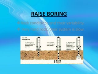
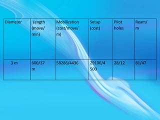
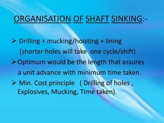
Presentation on shaft sinking
operation
RAISE BORING
Rock conditions and their variability.
 Very hard rock, their system is slow.
PARAMETERS FOR SOFT ROCK
(European coal fields):-
• Pilot hole diameter
• Drill pipe diameter
• Reaming Torque
• Type of driver (AC, DC ,hydraulic)gear reducer
• RPM
• Power: Pilot hole thrust & feed rates reaming pull, size of
drill pipe base plate and derrick dimensions, type of
transporter, water and air consumption.
• Dia /length/advance per unit time .
• Costs reduced due development of improved cutters with
average life being extended by fire fold.
PURPOSE
• Ore passes
• Ventilation
• Ventilation shafts
• Full sized shafts for coal mining.
ADVANTAGES:-
• No worker needs to be present while
excavation is on .
• Cost thus gets reduced in (developed
countries).
• Faster progress.
• Less damage to surrounding rock/thus
minimum support is needed.
• Smooth, stable walls, lead resistance for
ventilation.
DISADVANTAGE:-
• Change on rock conditions
• Costs are high for hard rocks.
• Access necessary.
• Initial cost of rig is high.
• Shaft should be dry.
OPERATION:-
• Pilot hole then reaming in one or more stages.
• Common is pilot hole down and reaming up.
SLUTCH COMPONENTS:-
• Rig – Rigid plate and structure
• Hydraulic, drilling and electrical equipment
are housed
CRAWLER DRIVEN BY CA /
RAILWHEELS:-
• Pilot hole is drilled through the stem with stabilizers and a
conventional drilling bit.
• Drill rod diameter (20 -31 cm)
• Length of the section is 1.5 m.
• Purpose of stabiliser is to ensure directional accuracy of the
pilot hole .
• Stem longest /reamer-stages / structural analysis of
required/balancing of tool by positioning cutters optimally.
• Geared reamers/conventional type .
• Best performance is achieved when cutter life and ROP are
optimized.
• Structural features- Ductility/Brittle abrasivity
• Removal of cuttings (should be effective )
Reduce rocks layer of cuttings 40%
• Drilling –air /water/foam/drilling fluid
D=W
Where D is DOP and W is applied load.
• Reaming
• RPM – wear/vibrations
• Adequate room/interference with production
Drilling down/reaming up is the cheapest option.
Rock quality and its response can change the boring
direction.
• Lining – strong rocks no lines/shotcret/rockbolt/± wire mesh/
steel lining.
• Cost
Diameter Length
(move/
min)
Mobilization
(cost/move/
m)
Setup
(cost)
Pilot
holes
Ream/
m
3 m 600/37
m
58286/4436 29100/4
500
28/12 81/47
KHERTI SHAFT DETAILS:-
• Adit section : For exploitation of ore body above 424 MSL
• Decline section: 5 mX3.25m size ,1 IN 9 from surface to364MSLand
306 MSL.
• Production shaft section:424 MSL
PRODUCTION SHAFT:-
• Upcast shaft-5.5 m dia
• Concrete lined
• Tower mounted 2870 KW 6 rope friction hoist with 2/14 t ships in
counter balance.
• Emergency escape and ladder way
• Hoisting speed : 2 stages 1)8m/s 2)18 m/s
SERVICE SHAFT:-
• Rectangular in shape
• Size : 6.11m X 4.93m.
• 2 cage hoisting compartments.
• Emergency escape cage & ladder way.
• Double deck cages guided by rigid rail guides.
• Shaft is provided with a steel head frame and
is 1600 cylindrical double drum hoist with
one drum clutched.
ORGANISATION OF SHAFT SINKING:-
 Drilling + mucking/hoisting + lining
(shorter holes will take one cycle/shift)
Optimum would be the length that assures
a unit advance with minimum time taken.
 Min. Cost principle ( Drilling of holes ,
Explosives, Mucking, Time taken).
Drilling Pattern :-
 Accuracy in the shape of excavation.
 Clean separation upto the desired depth.
 Uniform fragmentation.
 Minimum misfires(should be avoided).
 Damage is controlled (nearby structures).
Pattern :-
o Shape of the section
o Rock strength.
o Cleavage.
o Dip of strata.
o Water inflow.
o Hole loading structure.
Cartridge No. Of circles Diameter of holes Holes rate
32mm. 3 0.37,0.66,0.93 1-2-3
4 0.35,0.54,0.7,0.93 1-2-3-4
5 0.27,0.43,0.6,0.93 1-2-3-4-5
45mm. 3 0.3,0.6,0.95 1-3-6
4 0.25,0.48,0.72,0.96 1-2-3-5
LINING IN SHAFTS
• Factors:-
Type of lining.
Hydro geological conditions (geotechnical parameters).
Shaft function.
Planned life time.
Shape of shaft section.
Depth.
Availability of construction materials.
Construction cost .
Chemical activity.
Repairs and maintenance .
Temporary lining:-
• Against falling rocks (6-40m)
• Necessary when tech. is advancing
Permanent lining:-
• Timber
• Brick
• Concrete blocks
• Concrete monolithic
• Reinforced concrete
• Tubbrs (cast iron and pre cast elements)
• Shotcrete (with wire mesh)
• Anchor bolts (a combination some times)
1.Brick lining:-
• Was popular /ability to carry load immediately
/ease of repairs and resistance to corrosive
factors.
2.Concrete block lining:-
• Decreased seams
• Higher strength
• Less labour
• Intensive in comparison to brick lining
3.Timber Lining:-
Seldom.
Disadvantage:-
 Time and labour consuming
 Low strength
 High cost
 Substantial permeability.
Timber Lining
4.Monolithic concrete lining: –
Advantage:-
• Complete mechanization possible.
• Good bond between lining and shaft.
• Decreased labour cost.
• High strength.
Disadvantage:-
1. Less resistance to corrosive water
2. Sensitivity to rock mass movement
3. Inability to take load immediately
4. Difficult to repairs
 Some facts-
17-25mp is sufficient
Min:200mm max:800mm
(4-5m)
Collapsible steel forms /segment with seam
Sliding type – longer segments
5.Shotcrete lining:-
Composition:-
• Shotcrete
• Shotcrete + rock bolts +mesh
• RCC
• RCC +bolts (temp. supports)
Applicable in dry shafts
Very good bonding
High strength to low water
{ t=r0-ri , r = r0-ri }
σt(max)/F.S = 2P0(t+ri)2/t(t+2ri)
P0 = r h ( tan r(π/4-φ/2))
Φ = angle of internal friction
σt = (P0r0
2/(r0
2-ri
2))((1+ri
2)/r0
2)
= 2P0r0
2
σt = (P0)((r0=ri)2-2r0ri)/(r0+ri)(r0-ri)
=P0(r0+ri)/(r0-ri)-(2P0r0ri)/(r0
2-ri
2)
Primary Stresses:-
σr=∑rh
h=thickness of rock stratum
for 500 σr/σt=2to 3
Polyethylene –membrance to prevent corrosive
waters.
The following are the three categories
Cohesion less
Cohesive
Rocks
σr = p0
σt = 2p0 . ro
2 / r0
2 - ri
2
σt max / F.S = 2p0 . (t+ri)2 / (r0 - ri )( r0 + ri)
= 2p0 . (t+ri)2 / (t)( r0 + ri)
σt max / F.S = 2p0 . (t+ri)2 / (t)( t +2 ri)
t = { ( σt max / F.S )/( σt max /F.S – 2.po ) - 1 }
σt max = 0.67 fcu.
P0
fcu : Cube strength of concrete after 28 days
(British standard code )
rf : for applied load
rm : different srength in concrete
(due in sufficient copaction & difference in curving ).
rm = 1.5 and rf = 1.4
0.67/1.4 x1.5 = 2x0.01xd(t+ri)2 / (t)( t+2 ri)
.: t =ri [ (0.67fcu/2.1)/(0.67fcu/2.1 – 2x0.01d)} - 1]
d in mts , ri in mts , t in mm and fcu in N/mm2
Some Points :-
• Support of Shaft equipment and walls .
• Shallow square (timber support).
• Deep circular or spherical.
• Concrete lining mostly – mechanized/utilizes the
structure features of concrete,
easy least air flow resistance.
• Strengths 20 to 50 Mpa .
• Cast iron tubbings with concrete mantle welded
steel lining (water heads).
• Bitumen envelop for preventing damage due to
subsiding strata.
• Temporary support fos = 1.
• Permanent fos > 1 (lining conditions and life
space ).
• Primary stress σ v = Σ γ h.
• σ h /σ v = 2 to 3 < 500m depth .
• σh = σv . Ka Ka : co efficient of active stress.
• Stress distribution around shaft existing cracks ,
shaft diameter ,method of (D and B or boring
),time of exposure without support type of temp.
Support used and delay instead of permanent
lining .
• σh = σv . Ka Ka : co efficient of active stress.
• Polyethylene membrane for preventing corrosion
of concrete for water insulation.
• RMR and Q  Ka ( Horizontal design stress).
• Un supported span ( 15 – 25 m).
ThanK YoU

Shaft sinking operation

  • 1.
    Presentation on shaftsinking operation
  • 3.
    RAISE BORING Rock conditionsand their variability.  Very hard rock, their system is slow.
  • 4.
    PARAMETERS FOR SOFTROCK (European coal fields):- • Pilot hole diameter • Drill pipe diameter • Reaming Torque • Type of driver (AC, DC ,hydraulic)gear reducer • RPM • Power: Pilot hole thrust & feed rates reaming pull, size of drill pipe base plate and derrick dimensions, type of transporter, water and air consumption. • Dia /length/advance per unit time . • Costs reduced due development of improved cutters with average life being extended by fire fold.
  • 5.
    PURPOSE • Ore passes •Ventilation • Ventilation shafts • Full sized shafts for coal mining.
  • 6.
    ADVANTAGES:- • No workerneeds to be present while excavation is on . • Cost thus gets reduced in (developed countries). • Faster progress. • Less damage to surrounding rock/thus minimum support is needed. • Smooth, stable walls, lead resistance for ventilation.
  • 7.
    DISADVANTAGE:- • Change onrock conditions • Costs are high for hard rocks. • Access necessary. • Initial cost of rig is high. • Shaft should be dry.
  • 8.
    OPERATION:- • Pilot holethen reaming in one or more stages. • Common is pilot hole down and reaming up. SLUTCH COMPONENTS:- • Rig – Rigid plate and structure • Hydraulic, drilling and electrical equipment are housed
  • 9.
    CRAWLER DRIVEN BYCA / RAILWHEELS:- • Pilot hole is drilled through the stem with stabilizers and a conventional drilling bit. • Drill rod diameter (20 -31 cm) • Length of the section is 1.5 m. • Purpose of stabiliser is to ensure directional accuracy of the pilot hole . • Stem longest /reamer-stages / structural analysis of required/balancing of tool by positioning cutters optimally. • Geared reamers/conventional type . • Best performance is achieved when cutter life and ROP are optimized.
  • 10.
    • Structural features-Ductility/Brittle abrasivity • Removal of cuttings (should be effective ) Reduce rocks layer of cuttings 40% • Drilling –air /water/foam/drilling fluid D=W Where D is DOP and W is applied load. • Reaming • RPM – wear/vibrations • Adequate room/interference with production Drilling down/reaming up is the cheapest option. Rock quality and its response can change the boring direction. • Lining – strong rocks no lines/shotcret/rockbolt/± wire mesh/ steel lining. • Cost
  • 11.
  • 12.
    KHERTI SHAFT DETAILS:- •Adit section : For exploitation of ore body above 424 MSL • Decline section: 5 mX3.25m size ,1 IN 9 from surface to364MSLand 306 MSL. • Production shaft section:424 MSL PRODUCTION SHAFT:- • Upcast shaft-5.5 m dia • Concrete lined • Tower mounted 2870 KW 6 rope friction hoist with 2/14 t ships in counter balance. • Emergency escape and ladder way • Hoisting speed : 2 stages 1)8m/s 2)18 m/s
  • 13.
    SERVICE SHAFT:- • Rectangularin shape • Size : 6.11m X 4.93m. • 2 cage hoisting compartments. • Emergency escape cage & ladder way. • Double deck cages guided by rigid rail guides. • Shaft is provided with a steel head frame and is 1600 cylindrical double drum hoist with one drum clutched.
  • 14.
    ORGANISATION OF SHAFTSINKING:-  Drilling + mucking/hoisting + lining (shorter holes will take one cycle/shift) Optimum would be the length that assures a unit advance with minimum time taken.  Min. Cost principle ( Drilling of holes , Explosives, Mucking, Time taken).
  • 15.
    Drilling Pattern :- Accuracy in the shape of excavation.  Clean separation upto the desired depth.  Uniform fragmentation.  Minimum misfires(should be avoided).  Damage is controlled (nearby structures).
  • 16.
    Pattern :- o Shapeof the section o Rock strength. o Cleavage. o Dip of strata. o Water inflow. o Hole loading structure.
  • 17.
    Cartridge No. Ofcircles Diameter of holes Holes rate 32mm. 3 0.37,0.66,0.93 1-2-3 4 0.35,0.54,0.7,0.93 1-2-3-4 5 0.27,0.43,0.6,0.93 1-2-3-4-5 45mm. 3 0.3,0.6,0.95 1-3-6 4 0.25,0.48,0.72,0.96 1-2-3-5
  • 18.
    LINING IN SHAFTS •Factors:- Type of lining. Hydro geological conditions (geotechnical parameters). Shaft function. Planned life time. Shape of shaft section. Depth. Availability of construction materials. Construction cost . Chemical activity. Repairs and maintenance .
  • 19.
    Temporary lining:- • Againstfalling rocks (6-40m) • Necessary when tech. is advancing Permanent lining:- • Timber • Brick • Concrete blocks • Concrete monolithic • Reinforced concrete • Tubbrs (cast iron and pre cast elements) • Shotcrete (with wire mesh) • Anchor bolts (a combination some times)
  • 20.
    1.Brick lining:- • Waspopular /ability to carry load immediately /ease of repairs and resistance to corrosive factors. 2.Concrete block lining:- • Decreased seams • Higher strength • Less labour • Intensive in comparison to brick lining
  • 21.
    3.Timber Lining:- Seldom. Disadvantage:-  Timeand labour consuming  Low strength  High cost  Substantial permeability.
  • 22.
  • 23.
  • 24.
    Advantage:- • Complete mechanizationpossible. • Good bond between lining and shaft. • Decreased labour cost. • High strength.
  • 25.
    Disadvantage:- 1. Less resistanceto corrosive water 2. Sensitivity to rock mass movement 3. Inability to take load immediately 4. Difficult to repairs  Some facts- 17-25mp is sufficient Min:200mm max:800mm (4-5m) Collapsible steel forms /segment with seam Sliding type – longer segments
  • 26.
    5.Shotcrete lining:- Composition:- • Shotcrete •Shotcrete + rock bolts +mesh • RCC • RCC +bolts (temp. supports) Applicable in dry shafts Very good bonding High strength to low water
  • 27.
    { t=r0-ri ,r = r0-ri } σt(max)/F.S = 2P0(t+ri)2/t(t+2ri) P0 = r h ( tan r(π/4-φ/2)) Φ = angle of internal friction σt = (P0r0 2/(r0 2-ri 2))((1+ri 2)/r0 2) = 2P0r0 2 σt = (P0)((r0=ri)2-2r0ri)/(r0+ri)(r0-ri) =P0(r0+ri)/(r0-ri)-(2P0r0ri)/(r0 2-ri 2)
  • 28.
    Primary Stresses:- σr=∑rh h=thickness ofrock stratum for 500 σr/σt=2to 3 Polyethylene –membrance to prevent corrosive waters. The following are the three categories Cohesion less Cohesive Rocks
  • 29.
    σr = p0 σt= 2p0 . ro 2 / r0 2 - ri 2 σt max / F.S = 2p0 . (t+ri)2 / (r0 - ri )( r0 + ri) = 2p0 . (t+ri)2 / (t)( r0 + ri) σt max / F.S = 2p0 . (t+ri)2 / (t)( t +2 ri) t = { ( σt max / F.S )/( σt max /F.S – 2.po ) - 1 } σt max = 0.67 fcu. P0
  • 30.
    fcu : Cubestrength of concrete after 28 days (British standard code ) rf : for applied load rm : different srength in concrete (due in sufficient copaction & difference in curving ). rm = 1.5 and rf = 1.4 0.67/1.4 x1.5 = 2x0.01xd(t+ri)2 / (t)( t+2 ri) .: t =ri [ (0.67fcu/2.1)/(0.67fcu/2.1 – 2x0.01d)} - 1] d in mts , ri in mts , t in mm and fcu in N/mm2
  • 31.
    Some Points :- •Support of Shaft equipment and walls . • Shallow square (timber support). • Deep circular or spherical. • Concrete lining mostly – mechanized/utilizes the structure features of concrete, easy least air flow resistance. • Strengths 20 to 50 Mpa . • Cast iron tubbings with concrete mantle welded steel lining (water heads).
  • 32.
    • Bitumen envelopfor preventing damage due to subsiding strata. • Temporary support fos = 1. • Permanent fos > 1 (lining conditions and life space ). • Primary stress σ v = Σ γ h. • σ h /σ v = 2 to 3 < 500m depth . • σh = σv . Ka Ka : co efficient of active stress. • Stress distribution around shaft existing cracks , shaft diameter ,method of (D and B or boring ),time of exposure without support type of temp. Support used and delay instead of permanent lining .
  • 33.
    • σh =σv . Ka Ka : co efficient of active stress. • Polyethylene membrane for preventing corrosion of concrete for water insulation. • RMR and Q  Ka ( Horizontal design stress). • Un supported span ( 15 – 25 m). ThanK YoU