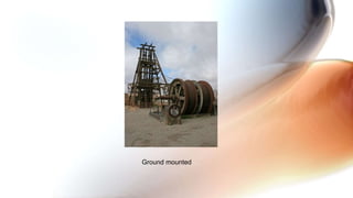
The document provides information about headgears used in mining. It discusses the different types of headgears based on material (steel, concrete), mounting (ground mounted, tower mounted), and hoisting systems (drum, friction). It also covers factors influencing headgear design like height, geometry, depth of shaft, and rope lead/slope calculations. The document is a reference material for various components, classifications, advantages and disadvantages of headgears.


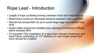

![lR is Rope lead or Rope plane, given by
lR = sqrt[ (h-ho)2 + (l-Rs)2 ]
h = calculated value of head frame height
l = horizontal distance between axis of drum shaft and
center of shaft section
ho = height of axis of drum shaft above shaft collar level
Rs = radius of head sheaves
Rope slope, given by
tan = (h-ho)/(l-Rs)
Calculation of Rope plane and rope slope](https://image.slidesharecdn.com/headgear-191230121339/85/Head-gear-21-320.jpg)
![When head sheaves are arranged in same vertical plane on separate
platforms, length of Rope planes are given by
lR1 = sqrt[ (h-ho)2 + (l-Rs)2 ]
lR2 = sqrt[ (h-∆h-ho)2 + (l-ls)2 ]
∆h = difference in elevation of head sheaves’ centers,
ls = horizontal distance between head sheaves’ centers](https://image.slidesharecdn.com/headgear-191230121339/85/Head-gear-22-320.jpg)