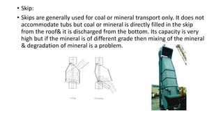
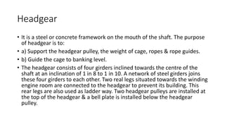
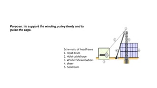
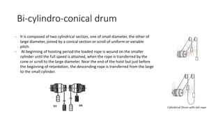
Mining machinery
Winding system
• The Purpose of Winding is to
1) Hoist the coal or mineral from underground to surface.
2) Lowering & rising of men.
3) Transport the material from surface to underground
4) Winding is a transport system from surface to underground through
shaft when the mine is deep. It is more or less same as we see a lift in a
multiplex building.
Main equipment
• 1) Headgear
• 2) Pulley (headgear pulley)
• 3) Cage
• 4) Skip
• 5) Winding rope
• 6) Winding drum
• 7) Guides
• 8) Keps
• 9) Suspension gear
• 10) Electrical motor
• Cage:
• It is a lift like structure suspended from winding rope by means of
suspension gear arrangement. It is used for the transportation of men
& materials. It is made up of steel, iron & very strong in construction.
• A track is provided on the floor with catches to prevent the
movement of the tubs. It is open with two sides & provided with
collapsible door. Men travelling in the cage provides a hand bar on
the sides for holding.
• The types of cage are as follows:
• a) Single deck single cage (only one tub).
• b) Tension cage – two tubs or more in one cage.
• c) Double deck single cage (one tub on each floor).
• d) Double deck tension cage (two or more tubs on each floor).
• Skip:
• Skips are generally used for coal or mineral transport only. It does not
accommodate tubs but coal or mineral is directly filled in the skip
from the roof& it is discharged from the bottom. Its capacity is very
high but if the mineral is of different grade then mixing of the mineral
& degradation of mineral is a problem.
Headgear
• It is a steel or concrete framework on the mouth of the shaft. The purpose
of headgear is to:
• a) Support the headgear pulley, the weight of cage, ropes & rope guides.
• b) Guide the cage to banking level.
• The headgear consists of four girders inclined towards the centre of the
shaft at an inclination of 1 in 8 to 1 in 10. A network of steel girders joins
these four girders to each other. Two real legs situated towards the winding
engine room are connected to the headgear to prevent its building. This
rear legs are also used as ladder way. Two headgear pulleys are installed at
the top of the headgear & a bell plate is installed below the headgear
pulley.
Schematic of headframe
1. Hoist drum
2. Hoist cable/rope
3. Winder Sheave/wheel
4. sheer
5. hoistroom
Purpose : to support the winding pulley firmly and to
guide the cage.
Headgear Pulley
• It is made up of hard steel. Its construction should be such that its
weight is less.
• Its diameter should be such that it should minimise the bending
stresses in the rope. Generally its diameter is 100 to 120 times
diameter of the rope.
• The large size pulleys are made in two parts & bolted together.
• The groove is made of renewable soft steel.
• The angle of fleet which is the angle between the vertical plane of
the pulley and the rope when the cage is at the pit top and or pit
bottom, should not exceed 1.5 degree.
• More fleet angle results in wear of the rope and wear of the pulley.
Cage attachment
If the fleet angle is too big, the wire
will tend to pull away from the
flange as the layer changes. It will want
to spool towards the centre and so leave
gaps. Gaps mean ragged spooling, which
means (at best) excessive rope wear, or
(at worst) snagging, catastrophic system
failure and physical danger to all those
around.
• A typical arrangement of attaching cage to the winding rope consists
of attaching the cage to a triangular distribution plate,
• which is further connected to safety detaching hook through bull
chains or D links.
• The detaching hook is further connected to rope capel which may be
a cone type capel or reliance capel.
• These attachments are generally made up of mild steel or wrought
iron.
Detaching hook
• Detaching hook which is always placed below the rope capel is a
safety device which acts when a overwind takes place. Its purpose is
to suspend the cage in the headgear when overwind takes place, and
at the same time it releases the rope to go over the pulley.
• These are used in drum winders, not used in friction winder.
• two types of detaching hooks are in common use :
• Ormerod detaching safety hook, and
• King detaching safety hook
Ormerod detaching safety hook
• It consists of three mild steel plates i.e. one centre plate and two outer
plates.
• Plates are assembled on a common centre pivot and a copper rivet
passes through a small hole of all three plates when assembled.
• Top portion of plates is attached to a D link hung from the rope capel by
means of slotted holes and the bottom portion open out to give the
appearance of the wedge.
• The outer plates actually transfer the load of the cage to the rope.
• A plate or a bell set is fixed on the horizontal member of the headgear
frame is required for operation of the safety hook in case of a overwind.
• The hook in its assembled form cannot pass through the bell-set.
fig : Ormerod detaching safety hook
King detaching safety hook
Safety catches
• As a safeguard against the failure of the detaching plate to hold the
cage, safety catches are fitted in the headgear.
• These basically consists of short levers mounted in the headgear at
intervals that vary from 0.3m to 1m. These are located above the
normal running range of cage.
• In the case of overwind, catches are lifted to pass the cage upto
headgear and then fall back and hence prevent cage to fall back into
the shaft.
• A mechanical linkage is provided to so that all catches may be
withdrawn simultaneously in order to lower the cage after an
overwind.
• Safety catches
Keps
• Shafts used for cage winding are equipped with kep gears at the pit
bank, which support and hold the cage steady at the correct level for
loading and unloading of tubs/mine cars.
• The load in the cage causes the rope to stretch; therefore as the
loaded tubs/cars are taken out and replaced by empties there would
be a tendency for the cage to move up and down due to the natural
elasticity in the rope. Consequently, keps are provided to give support
to the cage.
Guides
• Guides are used to give the direction to the cages in motion in the shaft to avoid
collision between them.
1. Rigid guides 2. flexible guides
1. Rigid guides :
• These guides are made of steel or wood. They are of rectangular cross section,
usually 10 X 20 cm. & are fixed by countersunk bolts to the buntons placed across
the shaft at the intervals of 1.8 to 3 meter.
• The weight of the rail section varies from 20-to 55-kgf/m. lengths & length of the
rail piece is up to 13 meter. Only one line of bunton is required in the middle of
the shaft for fixation of rigid guide.
• Generally one line of guide is enough but sometimes two guides /cages are used.
These guides are used for deep shaft.
2. Flexible guides:
• These guides are made of steel wire ropes. The ropes used may be of
locked coil construction or a guide rope itself.
• These guides are suspended in a vertical shaft from two headgears,
by using a reliance rope capel which is a screwed on the on the cross
member of the headgear as shown in figure.
• At the pit bottom the rope passes through the holes provided in the
pit bottom deck & the required amount of tensioning weight is
attached to the rope.
• In shallow shaft 2 or 3 rope guides or cage
are sufficient but for deep shaft four guides
per cage are used.
Comparison
1) No oscillation.
2) Less space required.
3) Costly
4) Difficult installation
5) More maintenance
6) More resistance to fire
7) No load on headgear
8) Only damaged parts can be
replaced
9) Bun tons are required through the
shaft
10) More life
1) Oscillation of cage is there
2) More space required
3) Cheap
4) Easy installation
5) Less maintenance
6) Less resistance to fire
7) Complete load on headgear
8) Any damage causes full
replacement
9) No bun tons are required
10) Less life
Rigid guide flexible/ rope guide
Safety devices
Mechanical breaks :
• Requirements of mechanical brakes are as under:
• 1) When the cage is at rest, brakes should be in on position.
• 2) When the cage in motion, brakes should be in off position.
• 3) In case of power failure, the brakes should come in on position
automatically.
• 4) Brakes should not be used for speed control.
Types of mechanical brakes
• Anchored post brakes.
• Centre suspended calliper post brakes
Suspended caliper brake
• It consists of two curved arm namely front & rear,
front curved are consist of two triangular levers.
• These triangular levers are connected to the main
lever through tie rod, Main lever, which is pivoted,
consists a suspended weight & a piston rod to
another end.
• Working : When there is no power to the brake
engine the suspended weight falls so that main
lever moves in anticlockwise direction about. Due
to this tie rod T1 & T3 are pulled to operate the L1
& L2 in anticlockwise & clockwise direction
respectively. These triangular levers pull the tie rod
T2 & T4 so that rear curved arm is closed to the
brake path & also pushes the front curved arm
towards the brake path. In this way a uniform
braking effect is obtained
• Each post carries its own curved brake block fitted
with brake lining. The front post carries a triangular
lever at its top. This lever is connected with rear
post by a tie rod & the main lever through another
tie rod.
• The main lever is pivoted & its anchor end carries a
suspended weight.
• When there is no rod to the brake engine, the main
lever fails down under the suspended weight due to
this tie rod T1 is pulled downward to operate a
triangular lever in anticlockwise direction due to
which the tie rod T2 is pulled.
• Force acting on a front post towards the brake path,
applied the brakes & anchor force which is acting
on the rear post by tie rod T2 applied the braking
effect to the drum.
• To operate a winding drum power is supplied to the
brake engine to raise the piston rod which lifts the
main lever upwards against the upward against the
suspended weight. It will push the tie rod even
upward to operate the triangular lever, which pulls
the front post & at the same time pushes the rear
post through tie rod T2. Thus the brakes are away
from the brake path & the drum is free to rotate.
• The main disadvantage of this brake is that the wear & tear
of the brake lining is not uniform & it is more at top &
minimum at the bottom.
Anchored Post Brakes
• Reverse Direction Prevention Switch:
• It trips power if the winding engineman by mistake operates the motor in
wrong direction.
• Time Limit Switch:
• It is mounted on the headgear. It trips power if the ascending cage crosses
decking level.
• Tachometer Generator:
• It is connected to the winding drum for normal rpm it generates a normal
amount of current, but if the gearbox is faulty, the tachometer generator
will not generate the normal current & it will trip power to the motor.
• Warning Bell:
• When the cage is at a distance of two revolutions before reaching the
decking level, a warning bell warns the operator to remains alternative.
• Wedge arresters for downgoing cage.
Winding Drum
• Drum winder :
• These have one end of the winder rope attached to the drum and coil ropes onto
and off the drum in one or more layers during winding.
• Cylindrical drum:
• A cylindrical or parallel drum is a simple and robust in construction. The winding
ropes are attached at each end of the drum barrel, and arrange to coil on the
drum in the opposite direction, so that when the drum rotates one cage will be
raised and the other lowered.
• The rope coiling underneath the drum is called under lap and the rope coiling
over the top of the drum is the overlap. It may be either grooved or plain.
• Its serious drawback is that it can be used for shallow shaft only. In winding from
deep shaft, the weight of one winding rope will exceed the weight of coal raised
per wind. Thus there will an excessive load on engine when starting and negative
load towards the end of the wind causing heavy brake wear.
• This unbalancing of load in cylindrical drums can be reduced by tail ropes.
• The advantage of using tail rope is that only load against the engine
will be the constant load of coal raised, resulting in better control of
engine and reduce power consumption.
• But the use of tail rope has the following disadvantages:
• a. The total masses to be accelerated and decelerated are increased.
• b. Extra cost of tail rope is incurred.
• c. Weight on cappel is increased.
Bi-cylindro-conical drum
- It is composed of two cylindrical section, one of small diameter, the other of
large diameter, joined by a conical section or scroll of uniform or variable
pitch.
- At beginning of hoisting period the loaded rope is wound on the smaller
cylinder until the full speed is attained, when the rope is transferred by the
cone or scroll to the large diameter. Near the end of the hoist but just before
the beginning of retardation, the descending rope is transferred from the large
to the small cylinder.
• A bi-cylindro-conical drum suffers from the following Disadvantages:-
• a. It is heavier and more expensive than a cylindrical drum.
• b. For deep winding the drum size becomes excessive.
• c. Rope lying on conical portion may occupy more space than parallel
sided drum and they may cause trouble due to angle of fleet.
Duty cycle of winder engine
• Duty cycle of winder engine comprises of :
1. An acceleration period during which the winder reaches the
maximum speed.
2. An acceleration period during which the revolutions of the winder
are constant.
3. An retardation period during which winder speed is brought down
from maximum to zero, bringing the system at rest.
4. Decking period during which the loaded mine tubs are removed and
empty mine tubs are pushed into the cage.
• The first three process of duty cycle constitute the winding cycle of the
winder.
• The duty cycle of a winder is shown on a graph by showing its angular
velocity or torque on y axis and time on x axis.
• Torque required during various stages of the duty cycle may be considered
as follows :
a) Torque due to cages, tubs and mineral.
b) Torque due to unbalanced rope in the shaft.
c) Torque due to frictional force.
d) Torque due to forces causing acceleration and retardation.
• The first of these three are static torque and the last one is dynamic
torque.
Friction winding
• The friction hoist was invented by Frederick Koepe, so they are often
called Koepe winders.
• A friction winder is a vertical shaft winding system in which
conveyances transporting either people or materials are raised and
lowered by means of friction between single or multiple head ropes
and a driving sheave.
• Friction winders use tail ropes and do not have the haulage rope fixed
to the drum, but instead passed around it. The tail ropes offset the
need for the motor to overcome the weight of the conveyance and
hoisting rope, thereby reducing the required horsepower of the
winding motor by up to 30%, with the overall power consumption
remaining the same.
• The basic principle underlying the working of a friction winder is the
fact that a belt or hoist rope passing over a wheel driven by prime
mover, has different tensions at points where the rope enters the
wheel and where it leaves the wheel.
•
• Two types of koepe winders :
1. Ground koepe and
2. tower mounted koepe
Tower mounted koepe winder has advantages
Over ground as:
i. A large angle of rope contact on the sheave
ii. Winding rope protected from weather.
iii. Eliminates any obstruction due to winder on the ground.
Advantages of koepe over drum winder
Qn. Ore is hoisted from 620m depth using a single skip of 7 tonne payload. The skip winding system
has constant acceleration/ deceleration of 1m/s2 and a constant speed of 10m/s. the skip loading
time and unloading time are 120 and 60s, respectively. Considering the overall utilization of the skip
as 70%, then calculate the maximum daily capacity of the winding system(in tonne).
• Solution:
Openwinding system in mine machinery.pptx

Openwinding system in mine machinery.pptx

  • 1.
  • 2.
    • The Purposeof Winding is to 1) Hoist the coal or mineral from underground to surface. 2) Lowering & rising of men. 3) Transport the material from surface to underground 4) Winding is a transport system from surface to underground through shaft when the mine is deep. It is more or less same as we see a lift in a multiplex building.
  • 3.
    Main equipment • 1)Headgear • 2) Pulley (headgear pulley) • 3) Cage • 4) Skip • 5) Winding rope • 6) Winding drum • 7) Guides • 8) Keps • 9) Suspension gear • 10) Electrical motor
  • 4.
    • Cage: • Itis a lift like structure suspended from winding rope by means of suspension gear arrangement. It is used for the transportation of men & materials. It is made up of steel, iron & very strong in construction. • A track is provided on the floor with catches to prevent the movement of the tubs. It is open with two sides & provided with collapsible door. Men travelling in the cage provides a hand bar on the sides for holding. • The types of cage are as follows: • a) Single deck single cage (only one tub). • b) Tension cage – two tubs or more in one cage. • c) Double deck single cage (one tub on each floor). • d) Double deck tension cage (two or more tubs on each floor).
  • 5.
    • Skip: • Skipsare generally used for coal or mineral transport only. It does not accommodate tubs but coal or mineral is directly filled in the skip from the roof& it is discharged from the bottom. Its capacity is very high but if the mineral is of different grade then mixing of the mineral & degradation of mineral is a problem.
  • 6.
    Headgear • It isa steel or concrete framework on the mouth of the shaft. The purpose of headgear is to: • a) Support the headgear pulley, the weight of cage, ropes & rope guides. • b) Guide the cage to banking level. • The headgear consists of four girders inclined towards the centre of the shaft at an inclination of 1 in 8 to 1 in 10. A network of steel girders joins these four girders to each other. Two real legs situated towards the winding engine room are connected to the headgear to prevent its building. This rear legs are also used as ladder way. Two headgear pulleys are installed at the top of the headgear & a bell plate is installed below the headgear pulley.
  • 7.
    Schematic of headframe 1.Hoist drum 2. Hoist cable/rope 3. Winder Sheave/wheel 4. sheer 5. hoistroom Purpose : to support the winding pulley firmly and to guide the cage.
  • 9.
    Headgear Pulley • Itis made up of hard steel. Its construction should be such that its weight is less. • Its diameter should be such that it should minimise the bending stresses in the rope. Generally its diameter is 100 to 120 times diameter of the rope. • The large size pulleys are made in two parts & bolted together. • The groove is made of renewable soft steel. • The angle of fleet which is the angle between the vertical plane of the pulley and the rope when the cage is at the pit top and or pit bottom, should not exceed 1.5 degree. • More fleet angle results in wear of the rope and wear of the pulley.
  • 10.
    Cage attachment If thefleet angle is too big, the wire will tend to pull away from the flange as the layer changes. It will want to spool towards the centre and so leave gaps. Gaps mean ragged spooling, which means (at best) excessive rope wear, or (at worst) snagging, catastrophic system failure and physical danger to all those around.
  • 11.
    • A typicalarrangement of attaching cage to the winding rope consists of attaching the cage to a triangular distribution plate, • which is further connected to safety detaching hook through bull chains or D links. • The detaching hook is further connected to rope capel which may be a cone type capel or reliance capel. • These attachments are generally made up of mild steel or wrought iron.
  • 12.
    Detaching hook • Detachinghook which is always placed below the rope capel is a safety device which acts when a overwind takes place. Its purpose is to suspend the cage in the headgear when overwind takes place, and at the same time it releases the rope to go over the pulley. • These are used in drum winders, not used in friction winder. • two types of detaching hooks are in common use : • Ormerod detaching safety hook, and • King detaching safety hook
  • 13.
    Ormerod detaching safetyhook • It consists of three mild steel plates i.e. one centre plate and two outer plates. • Plates are assembled on a common centre pivot and a copper rivet passes through a small hole of all three plates when assembled. • Top portion of plates is attached to a D link hung from the rope capel by means of slotted holes and the bottom portion open out to give the appearance of the wedge. • The outer plates actually transfer the load of the cage to the rope. • A plate or a bell set is fixed on the horizontal member of the headgear frame is required for operation of the safety hook in case of a overwind. • The hook in its assembled form cannot pass through the bell-set.
  • 14.
    fig : Ormeroddetaching safety hook
  • 15.
  • 16.
    Safety catches • Asa safeguard against the failure of the detaching plate to hold the cage, safety catches are fitted in the headgear. • These basically consists of short levers mounted in the headgear at intervals that vary from 0.3m to 1m. These are located above the normal running range of cage. • In the case of overwind, catches are lifted to pass the cage upto headgear and then fall back and hence prevent cage to fall back into the shaft. • A mechanical linkage is provided to so that all catches may be withdrawn simultaneously in order to lower the cage after an overwind.
  • 17.
  • 18.
    Keps • Shafts usedfor cage winding are equipped with kep gears at the pit bank, which support and hold the cage steady at the correct level for loading and unloading of tubs/mine cars. • The load in the cage causes the rope to stretch; therefore as the loaded tubs/cars are taken out and replaced by empties there would be a tendency for the cage to move up and down due to the natural elasticity in the rope. Consequently, keps are provided to give support to the cage.
  • 19.
    Guides • Guides areused to give the direction to the cages in motion in the shaft to avoid collision between them. 1. Rigid guides 2. flexible guides 1. Rigid guides : • These guides are made of steel or wood. They are of rectangular cross section, usually 10 X 20 cm. & are fixed by countersunk bolts to the buntons placed across the shaft at the intervals of 1.8 to 3 meter. • The weight of the rail section varies from 20-to 55-kgf/m. lengths & length of the rail piece is up to 13 meter. Only one line of bunton is required in the middle of the shaft for fixation of rigid guide. • Generally one line of guide is enough but sometimes two guides /cages are used. These guides are used for deep shaft.
  • 20.
    2. Flexible guides: •These guides are made of steel wire ropes. The ropes used may be of locked coil construction or a guide rope itself. • These guides are suspended in a vertical shaft from two headgears, by using a reliance rope capel which is a screwed on the on the cross member of the headgear as shown in figure. • At the pit bottom the rope passes through the holes provided in the pit bottom deck & the required amount of tensioning weight is attached to the rope. • In shallow shaft 2 or 3 rope guides or cage are sufficient but for deep shaft four guides per cage are used.
  • 21.
    Comparison 1) No oscillation. 2)Less space required. 3) Costly 4) Difficult installation 5) More maintenance 6) More resistance to fire 7) No load on headgear 8) Only damaged parts can be replaced 9) Bun tons are required through the shaft 10) More life 1) Oscillation of cage is there 2) More space required 3) Cheap 4) Easy installation 5) Less maintenance 6) Less resistance to fire 7) Complete load on headgear 8) Any damage causes full replacement 9) No bun tons are required 10) Less life Rigid guide flexible/ rope guide
  • 22.
    Safety devices Mechanical breaks: • Requirements of mechanical brakes are as under: • 1) When the cage is at rest, brakes should be in on position. • 2) When the cage in motion, brakes should be in off position. • 3) In case of power failure, the brakes should come in on position automatically. • 4) Brakes should not be used for speed control. Types of mechanical brakes • Anchored post brakes. • Centre suspended calliper post brakes
  • 23.
    Suspended caliper brake •It consists of two curved arm namely front & rear, front curved are consist of two triangular levers. • These triangular levers are connected to the main lever through tie rod, Main lever, which is pivoted, consists a suspended weight & a piston rod to another end. • Working : When there is no power to the brake engine the suspended weight falls so that main lever moves in anticlockwise direction about. Due to this tie rod T1 & T3 are pulled to operate the L1 & L2 in anticlockwise & clockwise direction respectively. These triangular levers pull the tie rod T2 & T4 so that rear curved arm is closed to the brake path & also pushes the front curved arm towards the brake path. In this way a uniform braking effect is obtained
  • 24.
    • Each postcarries its own curved brake block fitted with brake lining. The front post carries a triangular lever at its top. This lever is connected with rear post by a tie rod & the main lever through another tie rod. • The main lever is pivoted & its anchor end carries a suspended weight. • When there is no rod to the brake engine, the main lever fails down under the suspended weight due to this tie rod T1 is pulled downward to operate a triangular lever in anticlockwise direction due to which the tie rod T2 is pulled. • Force acting on a front post towards the brake path, applied the brakes & anchor force which is acting on the rear post by tie rod T2 applied the braking effect to the drum. • To operate a winding drum power is supplied to the brake engine to raise the piston rod which lifts the main lever upwards against the upward against the suspended weight. It will push the tie rod even upward to operate the triangular lever, which pulls the front post & at the same time pushes the rear post through tie rod T2. Thus the brakes are away from the brake path & the drum is free to rotate. • The main disadvantage of this brake is that the wear & tear of the brake lining is not uniform & it is more at top & minimum at the bottom. Anchored Post Brakes Anchored Post Brakes
  • 25.
    • Reverse DirectionPrevention Switch: • It trips power if the winding engineman by mistake operates the motor in wrong direction. • Time Limit Switch: • It is mounted on the headgear. It trips power if the ascending cage crosses decking level. • Tachometer Generator: • It is connected to the winding drum for normal rpm it generates a normal amount of current, but if the gearbox is faulty, the tachometer generator will not generate the normal current & it will trip power to the motor. • Warning Bell: • When the cage is at a distance of two revolutions before reaching the decking level, a warning bell warns the operator to remains alternative. • Wedge arresters for downgoing cage.
  • 26.
    Winding Drum • Drumwinder : • These have one end of the winder rope attached to the drum and coil ropes onto and off the drum in one or more layers during winding. • Cylindrical drum: • A cylindrical or parallel drum is a simple and robust in construction. The winding ropes are attached at each end of the drum barrel, and arrange to coil on the drum in the opposite direction, so that when the drum rotates one cage will be raised and the other lowered. • The rope coiling underneath the drum is called under lap and the rope coiling over the top of the drum is the overlap. It may be either grooved or plain. • Its serious drawback is that it can be used for shallow shaft only. In winding from deep shaft, the weight of one winding rope will exceed the weight of coal raised per wind. Thus there will an excessive load on engine when starting and negative load towards the end of the wind causing heavy brake wear. • This unbalancing of load in cylindrical drums can be reduced by tail ropes.
  • 27.
    • The advantageof using tail rope is that only load against the engine will be the constant load of coal raised, resulting in better control of engine and reduce power consumption. • But the use of tail rope has the following disadvantages: • a. The total masses to be accelerated and decelerated are increased. • b. Extra cost of tail rope is incurred. • c. Weight on cappel is increased.
  • 30.
    Bi-cylindro-conical drum - Itis composed of two cylindrical section, one of small diameter, the other of large diameter, joined by a conical section or scroll of uniform or variable pitch. - At beginning of hoisting period the loaded rope is wound on the smaller cylinder until the full speed is attained, when the rope is transferred by the cone or scroll to the large diameter. Near the end of the hoist but just before the beginning of retardation, the descending rope is transferred from the large to the small cylinder.
  • 31.
    • A bi-cylindro-conicaldrum suffers from the following Disadvantages:- • a. It is heavier and more expensive than a cylindrical drum. • b. For deep winding the drum size becomes excessive. • c. Rope lying on conical portion may occupy more space than parallel sided drum and they may cause trouble due to angle of fleet.
  • 32.
    Duty cycle ofwinder engine • Duty cycle of winder engine comprises of : 1. An acceleration period during which the winder reaches the maximum speed. 2. An acceleration period during which the revolutions of the winder are constant. 3. An retardation period during which winder speed is brought down from maximum to zero, bringing the system at rest. 4. Decking period during which the loaded mine tubs are removed and empty mine tubs are pushed into the cage.
  • 33.
    • The firstthree process of duty cycle constitute the winding cycle of the winder. • The duty cycle of a winder is shown on a graph by showing its angular velocity or torque on y axis and time on x axis. • Torque required during various stages of the duty cycle may be considered as follows : a) Torque due to cages, tubs and mineral. b) Torque due to unbalanced rope in the shaft. c) Torque due to frictional force. d) Torque due to forces causing acceleration and retardation. • The first of these three are static torque and the last one is dynamic torque.
  • 34.
    Friction winding • Thefriction hoist was invented by Frederick Koepe, so they are often called Koepe winders. • A friction winder is a vertical shaft winding system in which conveyances transporting either people or materials are raised and lowered by means of friction between single or multiple head ropes and a driving sheave. • Friction winders use tail ropes and do not have the haulage rope fixed to the drum, but instead passed around it. The tail ropes offset the need for the motor to overcome the weight of the conveyance and hoisting rope, thereby reducing the required horsepower of the winding motor by up to 30%, with the overall power consumption remaining the same.
  • 35.
    • The basicprinciple underlying the working of a friction winder is the fact that a belt or hoist rope passing over a wheel driven by prime mover, has different tensions at points where the rope enters the wheel and where it leaves the wheel. •
  • 36.
    • Two typesof koepe winders : 1. Ground koepe and 2. tower mounted koepe Tower mounted koepe winder has advantages Over ground as: i. A large angle of rope contact on the sheave ii. Winding rope protected from weather. iii. Eliminates any obstruction due to winder on the ground.
  • 37.
    Advantages of koepeover drum winder
  • 44.
    Qn. Ore ishoisted from 620m depth using a single skip of 7 tonne payload. The skip winding system has constant acceleration/ deceleration of 1m/s2 and a constant speed of 10m/s. the skip loading time and unloading time are 120 and 60s, respectively. Considering the overall utilization of the skip as 70%, then calculate the maximum daily capacity of the winding system(in tonne). • Solution: