Downloaded 10 times
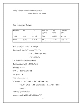
![Chapter 5: Equipment Design
Reactor Design:
Ln (Xi/Xf) = K/ LHSV [4].
Xi = inlet concentration (wt. %)
Xf = outlet Concentration (wt. %)
LHSV= Liquid hourly space velocity (hr-1
)
K= Rate constant (hr-1
)
Reactor 1
Average Rate Constant = 2.9818 hr-1
LHSV = 2.91/ Ln (0.88/.12)
= 1.474 hr-1
Volume (m3) = Volumetric flow rate (m3
/hr.) / LHSV
= 8.57 / 1.474
= 5.817 m3
20% Excess volume = (0.2*5.817) + 5.817
= 6.98 m3
Assume L/D = 5
Volume Of reactor = ( *D2
/4)*5D
6.98 = *5*D3/4
D = 1.33 m
L = 5* 1.33
= 6.67 m
Hydrogen quench coil design:
Hydrogen quench gas = 16.9 m/s max
Quench flow rate = 10807.4 kg/hr.
= 120.3 m3
/hr.
= 0.033427 m3
/sec
Area = 0.033427/16.9
=.00148 m2](https://image.slidesharecdn.com/dieselequipmentdesign-161110140217/85/Diesel-Production-Equipments-Design-1-320.jpg)
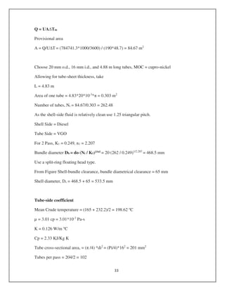
![*D2
/4 = 0.001978
D = 0.05 m
= 5 cm
Select 2 inch Schedule 160 pipe of ASME B31.3 [12].
Nominal size = 2 inch
Outside diameter = 2.375 inch
Wall thickness = .344 inch
Weight = 7.46 lb/ft.
Reactor 2
Average Rate Constant = 2.9818 hr-1
LHSV = 2.91/ Ln (0.86/.011)
= 0.67 hr-1
Volume (m3
) = Volumetric flow rate (m3
/hr.) / LHSV
= 54.87 / 0.67
= 8.190 m
20% Excess volume = (0.2*83.4) + 83.4
= 9.828 m3
Assume L/D = 5
Volume Of reactor = ( *D2
/4)*5D
100 = *5*D3
/4
D = 1.58 m
Length of reactor = 7.9 m
Hydrogen quench coil design:
Hydrogen quench gas = 16.9 m/s max
Quench flow rate = 3339.6 kg/hr.
= 37.1 m3
/hr.
= .0103 m3
/sec
Area = 0.0103/16.9](https://image.slidesharecdn.com/dieselequipmentdesign-161110140217/85/Diesel-Production-Equipments-Design-2-320.jpg)
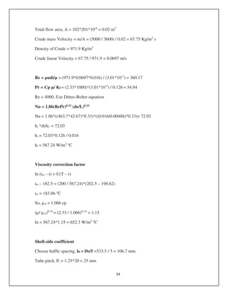
![=0.000609 m2
*D2
/4 = 0.000309
D = 0.0278 m
= 2.78 cm
= 3 cm
Select 1 ¼ inch schedule 160 pipe of ASME B31.3 material
Nominal size = 1 ¼ inch
Outside diameter = 1.6 inch
Wall thickness = 0.25 inch
Weight = 3.76 lb/ft.
Mechanical Design:
Reactor – 1
Maximum Allowable stress = 13100 psi for SA 340 material [8].
Design Pressure = 173.4 + 17.3
= 190.74 kg/cm2
Shell thickness t= PD/ (2fJ-P)
= (190.74*1.33)/ (2*921*0.85-190.74)
= 0.184 m
= 18.4 cm
Design of heads:
Hemispherical head design [2].
t = PD/4fJ
= (190.74*133)/ (4*0.85*921)
= 8.1 cm
Reactor – 2
Shell thickness t = PD/ (2fJ-P)
= (190.74*1.58)/ (2*921*0.85-190.74)
= 0.219 m](https://image.slidesharecdn.com/dieselequipmentdesign-161110140217/85/Diesel-Production-Equipments-Design-3-320.jpg)
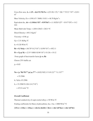
![= 21.9 cm
Hemispherical head design
t = PD/4fJ
= (190.74*158)/ (4*.85*921)
= 9.62 cm
Nozzle design
Allowable stress (psi) = 13100
Outside diameter of nozzle (in) = 6
Nominal wall thickness of nozzle (in) = 0.65
Nozzle corrosion allowance (in) = 0.078
Under tolerance allowance = 12.5%
Interior Pressure (psi) = 2390
UT (in) = 0.65*0.125
= 0.08125
Rn (in) = Do/2 – (Twall – C.A) + UT
= (6/2)-(0.65-.078)+0.08125
= 2.5
Treq (in) = 0.592
Inside diameter = 4.81586 in
Select 1 ¼ Cr- 1 Mo Material reactor
Select ASME B 16.5 material class 2500 Flanges [9].
Select nominal pipe size = 5 inch
Flange Diameter = 16 ½ inch
Number of bolts = 8
Bolt Diameter = 1 ¾ inch
Bolt Circle Diameter = 12 ¾ inch
Gasket
Inner ring inside diameter = 5 1/16 inch](https://image.slidesharecdn.com/dieselequipmentdesign-161110140217/85/Diesel-Production-Equipments-Design-4-320.jpg)
![= (1/472.9) + (1/2000) + ((0.020*ln (20/16))/ 2*50) + (20/ (16*2000))
+ (20/ (16*652.3))
1/Uo = 0.0052
Uo = 192.2961 w/m2 o
C
Well above assumed value of 190 w/m2 o
C
Pressure drop
Tube-side
Re = 463.69
From figure of friction factor jf vs. Re
jf = 0.025
Pt = 8 jf (L’/di) ( *ut2/2) (µ/ µw)-0.14
= 2[8*(0.025)(4.83*1000/16) + 2.5]*(971.9*0.06912
/ 2)* (1.15)-0.14
= 292.4 N/m2
This is acceptable.
Shell side
Linear Velocity = Gs / = 44.9 / 893.3 = 0.05 m/s
Re = 664.39
From figure of friction factor jf vs. Re
jf = 0.078
Pt = 8 jf (Ds/de)*(L/lB)*( *ut2/2)
= 8*(0.078)*(544.2/14.2)*(4.83*1000/157.2)*(893.3*0.052
/ 2)*](https://image.slidesharecdn.com/dieselequipmentdesign-161110140217/85/Diesel-Production-Equipments-Design-9-320.jpg)
![= 83004.54 N/m2
= 83 KPa =
This is acceptable [6].
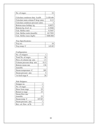
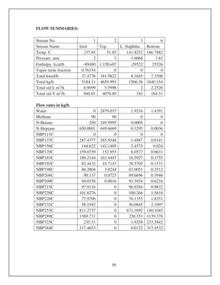
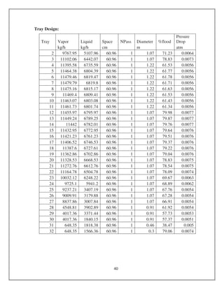
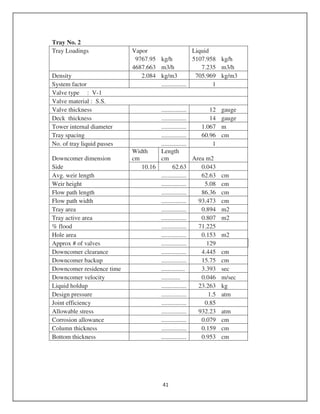
Fractionator Design
Fig. 5.1: Chemcad fractionator Flow sheet](https://image.slidesharecdn.com/dieselequipmentdesign-161110140217/85/Diesel-Production-Equipments-Design-10-320.jpg)

This document provides detailed specifications and calculations for the design of two reactors and associated equipment, including hydrogen quench coils, mechanical designs, nozzles, and heat exchangers. It covers reactor dimensions, design pressures, materials, and thermal properties, along with a fractionator's specifications, performing mass and energy balance calculations. The document encompasses critical calculations for heat load transfer, fluid velocities, pressure drops, and specifications of various components used in the reactor design process.


