The document summarizes the design of a 30,000 MTPA maleic anhydride production plant in India. It includes:
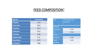
1) An introduction describing the importance of maleic anhydride and the aim to design a cost-effective plant using mixed butane as a feedstock.
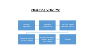
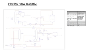
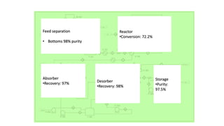
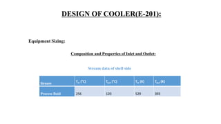
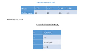
2) Details of the major process units - feedstock pretreatment, synthesis reactor, product recovery and purification.
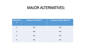
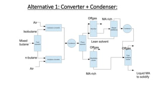
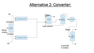
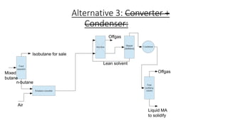
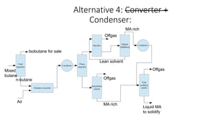
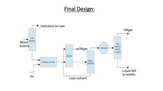
3) Evaluation of four process alternatives and selection of the final design incorporating a catalytic partial oxidation reactor, absorber for product recovery, and distillation for purification.
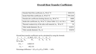
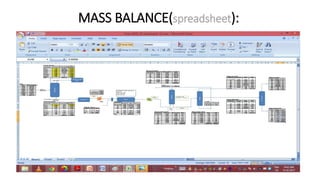
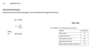
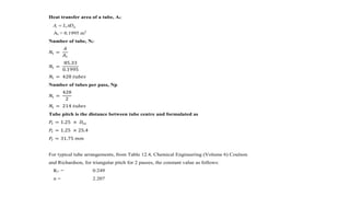
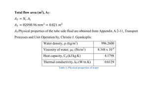
4) Key aspects of the design such as mass balances, equipment sizing for a shell and tube heat exchanger, and the

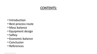


![Tube Side Pressure Drop
Friction factor, jf = 0.0036
Tube side pressure drop can be calculated from the equation below:
Where,
m = 0.25 for laminar flow, Re<2100 ; m = 0.14 for turbulent flow, Re>2100
Np = number of tube side passes
ΔPt= 57.53 Pa
2
]5.2))(/(8[
2
sm
w
tifps
u
DLjNP
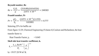
Shell Side
Fluid density, ρs (kg/m3
)
1.768
Viscosity, μsL (Ns/m2
)
2.073x10⁻⁵
Heat capacity, Csp (kJ/kg.K)
1.155
Thermal conductivity, ksf (W/m.K)
0.03081
Physical properties of reactor effluent](https://image.slidesharecdn.com/84ed97f8-9393-48a5-b3d7-b444f18582a8-150905042759-lva1-app6891/85/project-ppt-26-320.jpg)