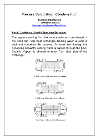
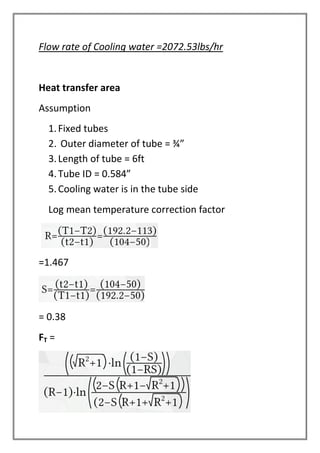
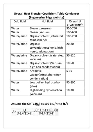
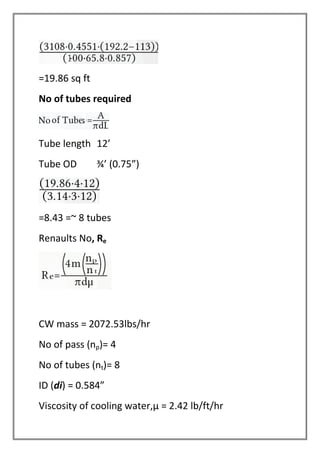
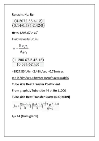
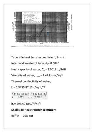
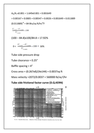
Process Calculation: Condensation
Chandran Udumbasseri
Technical Consultant
chandran.udumbasseri@gmail.com.
Part II: Condensor / Shell & Tube Heat Exchanger
The vapours coming from the vapour column is condensed in
the Shell and Tube heat exchanger. Cooling water is used to
cool and condense the vapours. As water has fouling and
depositing character cooling water is passed through the tube.
Organic Vapour is allowed to enter from shell side of the
exchanger.
The design is for 1 shell pass Multi tube pass Heat
exchanger
Tube length 6ft
Tube OD ¾”
Pitch square
Tube pitch 1” - (3/4” + ¼”)
Baffle segmental
Tube side cooling water
Fouling factor 0.0002
Shell side organic vapour
Fouling factor 0.0002
Fouling factor coefficients
Medium Fauling factor
Coefficient Resistance
W/m2/C m2.C/W
Cooling water 4000-6000 0.0002-0.0003
Organic
vapour/liquid
5000 0.0002
Light hydrocarbon 5000 0.0002
Heavy hydrocarbon 2000 0.0005
Condensing
organics
5000 0.0002
Heating fluids 5000 0.0002
Steam 4000-10000 0.0001-0.0025
Refrigerating brine 3000-5000 0.0002-0.0003
Tube side fluids Shell side fluids
Corrosive fluids
Coolin water
Fouling fluids
Less viscous liquids
High pressure steam
Hotter fluids
Condensing vapour
Fluids with large temperature
difference
Hot fluid (TEA vapour condensation)
Inlet temperature (T1) 192.2o
F (89o
C)
Outlet temperature (T2) 113o
F (45o
C)
Cold fluid (Chilled water)
Initial temperature, t1 50o
F (10o
C)
Outlet temperature t2 104o
F (40o
C)
Pressure of hot vapours 15psi
Pressure of cold fluid 50psi
Fluid (TEA) properties
Viscosity, ft/lb/hr (cP) 0.24395
Density, lb/cu ft 45.2915
Specific heat capacity Btu/lb/ft 0.4551
Specific gravity 0.7255
Thermal conductivity of TEA 1.003 Btu/sq ft.hr/F
Cooling water
Sp gravity 62.43 lb/cu ft
Viscosity 2.42lb/ft/hr (1cP)
Specific heat, 1.001 Btu/lb/ft
Thermal conductivity, 0.3455 Btu/sq ft/F
Calculation
Energy balance – No heat loss
Qcw= Qtea = mcw x Cpcw x (t2-t1) = mtea x Cptea x (T1-T2)
Boil up (mtea)= 1410.218Kg/hr= 3108.12 lbs/hr
Cptea = 0.4551Btu/lb/ft
T2 = 113o
F
T1 = 192.2o
F
CW requirement = ?
Cpcw = 1.001 Btu/lb/ft
t1 = 50o
F
t2 = 104o
F
Qtea = 3108.12 x 0.4551 x (192.2-113)
Qcw =? x 1.001x (104 – 50)
Flow rate of Cooling water =2072.53lbs/hr
Heat transfer area
Assumption
1.Fixed tubes
2. Outer diameter of tube = ¾”
3.Length of tube = 6ft
4.Tube ID = 0.584”
5.Cooling water is in the tube side
Log mean temperature correction factor
=1.467
= 0.38
FT =
Log mean temperature correction factor FT,
FT =0.857
LMTD
=65.8o
F
Heat Transfer Area
It is necessary to assume a value for overall heat
transfer coefficient. For industrial condensers for
organic solvent cooling, using cooling water the overall
heat transfer coefficient, the given range of value in
the below table is 100 to 200 BTU/hr-sq ft.F
Overall Heat Transfer Coefficient Table-Condenser
(Engineering Edge website)
Cold fluid Hot fluid Overall U
BTU/hr-sq ft/o
F
Water Steam (pressure) 350-750
Water Steam (vacuum) 100-600
Water/brine Organic solvent(saturated,
atmospheric)
100-200
Water/brine Organic
solvent(atmospheric, high
non condensation)
20-80
Water/brine Organic solvent (saturated,
vacuum)
50-120
Water/brine Organic solvent (Vacuum,
high non condensation)
10-50
Water/brine Aromatic
vapour(atmospheric non
condensation)
5-30
Water Low boiling hydrocarbon
(atm)
80-200
Water High boiling hydrocarbon
(vacuum)
10-30
Assume the OHTC (Ua) as 100 Btu/hr.sq ft.o
F
=19.86 sq ft
No of tubes required
Tube length 12’
Tube OD ¾’ (0.75”)
=8.43 =~ 8 tubes
Renaults No, Re
CW mass = 2072.53lbs/hr
No of pass (np)= 4
No of tubes (nt)= 8
ID (di) = 0.584”
Viscosity of cooling water,µ = 2.42 lb/ft/hr
Renaults No, Re
Re =11208.67 > 104
Fluid velocity (<1m)
=8927.80ft/hr =2.48ft/sec =0.78m/sec
u = 0.78m/sec,<1m/sec (result acceptable)
Tube side Heat transfer Coefficient
From graph JH Tube-side 44 at Re 11000
Tube side Heat Transfer Curve (D.Q.KERN)
JH= 44 (from graph)
Tube side heat transfer coefficient, ht = ?
Internal diameter of tube, di = 0.584”
Heat capacity of water, Cp = 1.001Btu/lb/ft
Viscosity of water, µcw = 2.42 lb-sec/sq ft
Thermal conductivity of water,
k = 0.3455 BTU/hr/sq ft/o
F
ht = 598.40 BTU/ft/hr/F
Shell side Heat transfer coefficient
Baffle 25% cut
Baffle spacing B = 0.5D = 4”
Equivalent diameter=
Pt = 1”
do = ¾”
De = 0.0795ft
C -= Pt-do = 1-3/4 = ¼ = 0.25”
Shell ID, Ds = 8”
Baffle spacing, B = 0.5 Ds = 0.5x 8 = 4”
Shell side cross flow area = ar =
0.056ft
Renaults No, Re – calculation
Mass velocity, G
=3108/0.056 = 55500 lb/sq ft/hr
Renailts No, Re =
=18086.7
Shell Side heat transfer curve (D.Q.KERN)
The last term in the equation is equated =1
Equivalent diameter of shell, De = 0.0795ft
Thermal conductivity of organic vapour, K = 1.003
BTU/hr/sq ft/F
Viscosity of organic vapour, µ = 0.24345 lb-sec/sq ft
Heat capacity of organic vapour, Cp = 0.4551 Btu/lb/ft
Organic vapour = triethyl amine
=587.19 Btu/sq ft/hr/F
Overall heat transfer coefficient, U
Stainless steel is used as tube material (MOC) with
thermal conductivity, 25Btu/sq ft/hr/F.
AO/AI= (0.75/0.584)2
= 1.649
(do-di)/2x25 = (0.75-0.584)/50 = 0.00332
1.649xx0.00332 = 0.00547
1/ht = 1/598 = 0.00167
1.649/587.19 = 0.0026
AO/AI x0.001 = 1.649x0.001 = 0.001649
= 0.00167 + 0.0005 + 0.00547 + 0.0026 + 0.001649 = 0.011889
(0.011889)-1
= 84 Btu/sq ft/hr/o
F
(100 – 84.8)x100/84.8 = 17.92%
Tube side pressure drop
Tube clearance = 0.25”
Baffle spacing = 4”
Cross area = (0.267x8)/(4x144) = 0.0037sq ft
Mass velocity =2072/0.0037 = 560000 lb/sq f/hr
Tube side frictional factor curve (D.Q.KERN)
Frictional factor at Re 11208
=0.00026sq ft/sq in
=0.00026 x 144 sq ft/sq ft
Frictional pressure drop Tube side
Ø is equated to =1
=1.56psi
Return loss
np = 6
Mass velocity = G = 560000lb/ sq ft/hr
S = 0.988
Δp = 0.44psi
P + Δp = 1.56 +0.44 = 2 psi < 10psi
Frictional pressure drop - Shell side
Clearance = 0.25”; Baffle spacing = 4”
Mass velocity = G = 55500 lb/sq ft/hr
Re = 18086.7
Shell side frictional factor curve (D.Q.KERN)
Friction factor = 0.0018x144 = 0.2592 sq ft/sq ft
No of baffles, nb,= 12/(4/12)=36
P = 0.46psi
Shell side pressure drop = 0.46psi <7psi
Overdesign:
The required total surface area of all tubes
= 3.14 x (3/4) x (1/12) x 12 x 8.43 = 19.85 sq ft
Design surface area
== 3.14 x (3/4) x (1/12) x12 x 8 = 18.85 sq ft
Difference % on required = 5.08% <10%
So the design is within requirement
Condenser Specification
Tube: = fixed
Tube size
OD = 3/4”
ID = 0.584”
Tube length = 12ft
MOC = SS316
No of tubes = 8
No of tube passes = 6
Tube pitch = square
Pitch length = 1”
Shell size
ID = 8”
MOC = ss
Shell length = 12ft
Baffles = 25% cut segments
Spacing = 4”
No of baffles = 36
Reference
1.PROCESS HEAT TRANSFER: D.Q.KERN: (Graphs,
curves, table information, equations and
formulas)
2.Engineering Edge site: for data tables

Process calculation condensation

  • 1.
    Process Calculation: Condensation ChandranUdumbasseri Technical Consultant chandran.udumbasseri@gmail.com. Part II: Condensor / Shell & Tube Heat Exchanger The vapours coming from the vapour column is condensed in the Shell and Tube heat exchanger. Cooling water is used to cool and condense the vapours. As water has fouling and depositing character cooling water is passed through the tube. Organic Vapour is allowed to enter from shell side of the exchanger.
  • 2.
    The design isfor 1 shell pass Multi tube pass Heat exchanger Tube length 6ft Tube OD ¾” Pitch square Tube pitch 1” - (3/4” + ¼”) Baffle segmental Tube side cooling water Fouling factor 0.0002 Shell side organic vapour Fouling factor 0.0002 Fouling factor coefficients Medium Fauling factor Coefficient Resistance W/m2/C m2.C/W Cooling water 4000-6000 0.0002-0.0003 Organic vapour/liquid 5000 0.0002 Light hydrocarbon 5000 0.0002 Heavy hydrocarbon 2000 0.0005 Condensing organics 5000 0.0002 Heating fluids 5000 0.0002 Steam 4000-10000 0.0001-0.0025 Refrigerating brine 3000-5000 0.0002-0.0003
  • 3.
    Tube side fluidsShell side fluids Corrosive fluids Coolin water Fouling fluids Less viscous liquids High pressure steam Hotter fluids Condensing vapour Fluids with large temperature difference Hot fluid (TEA vapour condensation) Inlet temperature (T1) 192.2o F (89o C) Outlet temperature (T2) 113o F (45o C) Cold fluid (Chilled water) Initial temperature, t1 50o F (10o C) Outlet temperature t2 104o F (40o C) Pressure of hot vapours 15psi Pressure of cold fluid 50psi Fluid (TEA) properties Viscosity, ft/lb/hr (cP) 0.24395 Density, lb/cu ft 45.2915 Specific heat capacity Btu/lb/ft 0.4551 Specific gravity 0.7255 Thermal conductivity of TEA 1.003 Btu/sq ft.hr/F Cooling water Sp gravity 62.43 lb/cu ft
  • 4.
    Viscosity 2.42lb/ft/hr (1cP) Specificheat, 1.001 Btu/lb/ft Thermal conductivity, 0.3455 Btu/sq ft/F Calculation Energy balance – No heat loss Qcw= Qtea = mcw x Cpcw x (t2-t1) = mtea x Cptea x (T1-T2) Boil up (mtea)= 1410.218Kg/hr= 3108.12 lbs/hr Cptea = 0.4551Btu/lb/ft T2 = 113o F T1 = 192.2o F CW requirement = ? Cpcw = 1.001 Btu/lb/ft t1 = 50o F t2 = 104o F Qtea = 3108.12 x 0.4551 x (192.2-113) Qcw =? x 1.001x (104 – 50)
  • 5.
    Flow rate ofCooling water =2072.53lbs/hr Heat transfer area Assumption 1.Fixed tubes 2. Outer diameter of tube = ¾” 3.Length of tube = 6ft 4.Tube ID = 0.584” 5.Cooling water is in the tube side Log mean temperature correction factor =1.467 = 0.38 FT =
  • 6.
    Log mean temperaturecorrection factor FT, FT =0.857 LMTD =65.8o F Heat Transfer Area It is necessary to assume a value for overall heat transfer coefficient. For industrial condensers for organic solvent cooling, using cooling water the overall heat transfer coefficient, the given range of value in the below table is 100 to 200 BTU/hr-sq ft.F
  • 7.
    Overall Heat TransferCoefficient Table-Condenser (Engineering Edge website) Cold fluid Hot fluid Overall U BTU/hr-sq ft/o F Water Steam (pressure) 350-750 Water Steam (vacuum) 100-600 Water/brine Organic solvent(saturated, atmospheric) 100-200 Water/brine Organic solvent(atmospheric, high non condensation) 20-80 Water/brine Organic solvent (saturated, vacuum) 50-120 Water/brine Organic solvent (Vacuum, high non condensation) 10-50 Water/brine Aromatic vapour(atmospheric non condensation) 5-30 Water Low boiling hydrocarbon (atm) 80-200 Water High boiling hydrocarbon (vacuum) 10-30 Assume the OHTC (Ua) as 100 Btu/hr.sq ft.o F
  • 8.
    =19.86 sq ft Noof tubes required Tube length 12’ Tube OD ¾’ (0.75”) =8.43 =~ 8 tubes Renaults No, Re CW mass = 2072.53lbs/hr No of pass (np)= 4 No of tubes (nt)= 8 ID (di) = 0.584” Viscosity of cooling water,µ = 2.42 lb/ft/hr
  • 9.
    Renaults No, Re Re=11208.67 > 104 Fluid velocity (<1m) =8927.80ft/hr =2.48ft/sec =0.78m/sec u = 0.78m/sec,<1m/sec (result acceptable) Tube side Heat transfer Coefficient From graph JH Tube-side 44 at Re 11000 Tube side Heat Transfer Curve (D.Q.KERN) JH= 44 (from graph)
  • 10.
    Tube side heattransfer coefficient, ht = ? Internal diameter of tube, di = 0.584” Heat capacity of water, Cp = 1.001Btu/lb/ft Viscosity of water, µcw = 2.42 lb-sec/sq ft Thermal conductivity of water, k = 0.3455 BTU/hr/sq ft/o F ht = 598.40 BTU/ft/hr/F Shell side Heat transfer coefficient Baffle 25% cut
  • 11.
    Baffle spacing B= 0.5D = 4” Equivalent diameter= Pt = 1” do = ¾” De = 0.0795ft C -= Pt-do = 1-3/4 = ¼ = 0.25” Shell ID, Ds = 8” Baffle spacing, B = 0.5 Ds = 0.5x 8 = 4” Shell side cross flow area = ar = 0.056ft Renaults No, Re – calculation Mass velocity, G
  • 12.
    =3108/0.056 = 55500lb/sq ft/hr Renailts No, Re = =18086.7 Shell Side heat transfer curve (D.Q.KERN) The last term in the equation is equated =1
  • 13.
    Equivalent diameter ofshell, De = 0.0795ft Thermal conductivity of organic vapour, K = 1.003 BTU/hr/sq ft/F Viscosity of organic vapour, µ = 0.24345 lb-sec/sq ft Heat capacity of organic vapour, Cp = 0.4551 Btu/lb/ft Organic vapour = triethyl amine =587.19 Btu/sq ft/hr/F Overall heat transfer coefficient, U Stainless steel is used as tube material (MOC) with thermal conductivity, 25Btu/sq ft/hr/F. AO/AI= (0.75/0.584)2 = 1.649 (do-di)/2x25 = (0.75-0.584)/50 = 0.00332 1.649xx0.00332 = 0.00547 1/ht = 1/598 = 0.00167 1.649/587.19 = 0.0026
  • 14.
    AO/AI x0.001 =1.649x0.001 = 0.001649 = 0.00167 + 0.0005 + 0.00547 + 0.0026 + 0.001649 = 0.011889 (0.011889)-1 = 84 Btu/sq ft/hr/o F (100 – 84.8)x100/84.8 = 17.92% Tube side pressure drop Tube clearance = 0.25” Baffle spacing = 4” Cross area = (0.267x8)/(4x144) = 0.0037sq ft Mass velocity =2072/0.0037 = 560000 lb/sq f/hr Tube side frictional factor curve (D.Q.KERN)
  • 15.
    Frictional factor atRe 11208 =0.00026sq ft/sq in =0.00026 x 144 sq ft/sq ft Frictional pressure drop Tube side Ø is equated to =1 =1.56psi Return loss np = 6 Mass velocity = G = 560000lb/ sq ft/hr S = 0.988 Δp = 0.44psi P + Δp = 1.56 +0.44 = 2 psi < 10psi
  • 16.
    Frictional pressure drop- Shell side Clearance = 0.25”; Baffle spacing = 4” Mass velocity = G = 55500 lb/sq ft/hr Re = 18086.7 Shell side frictional factor curve (D.Q.KERN) Friction factor = 0.0018x144 = 0.2592 sq ft/sq ft No of baffles, nb,= 12/(4/12)=36 P = 0.46psi
  • 17.
    Shell side pressuredrop = 0.46psi <7psi Overdesign: The required total surface area of all tubes = 3.14 x (3/4) x (1/12) x 12 x 8.43 = 19.85 sq ft Design surface area == 3.14 x (3/4) x (1/12) x12 x 8 = 18.85 sq ft Difference % on required = 5.08% <10% So the design is within requirement Condenser Specification Tube: = fixed Tube size OD = 3/4” ID = 0.584” Tube length = 12ft MOC = SS316 No of tubes = 8 No of tube passes = 6 Tube pitch = square
  • 18.
    Pitch length =1” Shell size ID = 8” MOC = ss Shell length = 12ft Baffles = 25% cut segments Spacing = 4” No of baffles = 36 Reference 1.PROCESS HEAT TRANSFER: D.Q.KERN: (Graphs, curves, table information, equations and formulas) 2.Engineering Edge site: for data tables