Downloaded 815 times
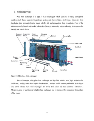
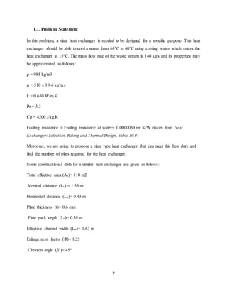
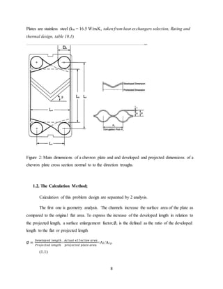

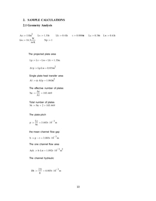
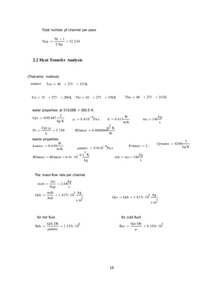
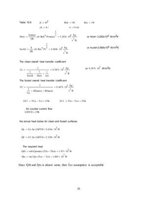
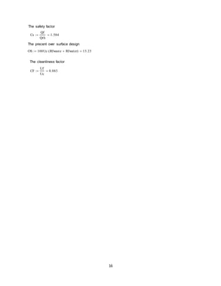

This document presents a design project for a plate type heat exchanger aimed at cooling a waste stream from 65°C to 40°C using cooling water at 15°C. It details the geometry and heat transfer analysis required to determine the number of plates needed, arriving at a total of 105 plates and the required heat duties for both clean and fouled conditions. The document also includes extensive calculations, assumptions, and references related to the design process.