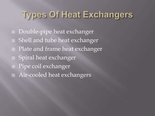
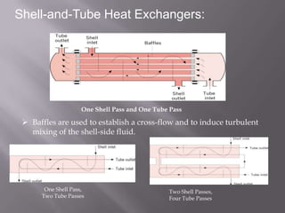
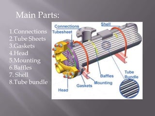
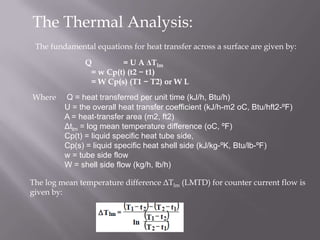
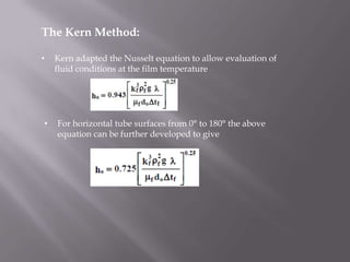
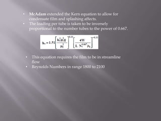
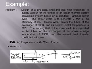
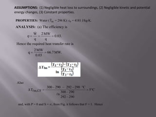
Prepared By:              Guided By:
Khalasi Bharat K.   Dr. Prabhakaran Sir
   HEAT EXCHANGER
   Types Of Heat Exchangers
   Shell-and-Tube Heat Exchangers
   Thermal Analysis
   Example
   References
   A heat exchanger is a device that is used to
    transfer thermal energy between
       two or more fluids,
       a solid surface and a fluid,
       solid particulates and a fluid
   Typical applications involve heating or cooling
    of a fluid stream of concern and evaporation or
    condensation of single- or multicomponent
    fluid streams.
   Double-pipe heat exchanger
   Shell and tube heat exchanger
   Plate and frame heat exchanger
   Spiral heat exchanger
   Pipe coil exchanger
   Air-cooled heat exchangers
Heat Exchanger Types

• Concentric-Tube Heat Exchangers


         Parallel Flow     Counterflow
• Cross-flow Heat Exchangers


   Finned-Both Fluids   Unfinned-One Fluid Mixed
       Unmixed              the Other Unmixed
Compact Heat Exchangers


• Achieve large heat rates per unit volume
• Large heat transfer surface areas per unit volume, small flow
  passages, and laminar flow.
Shell and Tube Heat
            Exchangers
• The shell and tube heat exchanger is the most
  common style found in industry.
• As the tube-side flow enters the exchanger,
  flow is directed into tubes that run parallel to
  each other. these tubes run through a shell
  that has a fluid passing through it.
• Heat energy is transferred through the tube
  wall into the cooler fluid.
• Heat transfer occurs primarily through
  conduction and convection.
Shell-and-Tube Heat Exchangers:


                    One Shell Pass and One Tube Pass

  Baffles are used to establish a cross-flow and to induce turbulent
   mixing of the shell-side fluid.


       One Shell Pass,                         Two Shell Passes,
      Two Tube Passes                          Four Tube Passes
Main Parts:
1.Connections
2.Tube Sheets
3.Gaskets
4.Head
5.Mounting
6.Baffles
7. Shell
8.Tube bundle
The Thermal Analysis:
 The fundamental equations for heat transfer across a surface are given by:

               Q        = U A ΔTlm
                = w Cp(t) (t2 − t1)
                = W Cp(s) (T1 − T2) or W L
Where    Q = heat transferred per unit time (kJ/h, Btu/h)
         U = the overall heat transfer coefficient (kJ/h-m2 oC, Btu/hft2-ºF)
         A = heat-transfer area (m2, ft2)
         Δtlm = log mean temperature difference (oC, ºF)
         Cp(t) = liquid specific heat tube side,
         Cp(s) = liquid specific heat shell side (kJ/kg-ºK, Btu/lb-ºF)
         w = tube side flow
         W = shell side flow (kg/h, lb/h)

The log mean temperature difference ΔTlm (LMTD) for counter current flow is
given by:
•   A correction factor is applied to the LMTD to allow for the departure
    from true counter current flow to determine the true temperature
    difference.
                ΔTm = Ft ΔTlm

•   The correction factor is a function of the fluid temperatures and the
    number of tube and shell passes and
•   Correlated as a function of two dimensionless temperature ratios
•       The correction factor Ft for a 1-2 heat exchanger which has 1
        shell pass and 2 or more even number of tube passes is given
        by:


•       The overall heat transfer coefficient U is the sum of several
        individual resistances as follows:


    •     The combined fouling coefficient hf can be
          defined as follows:
Area of Flow:
•   Shell side cross flow area aS is given by


Spacing Required:
•   Spacing does not normally exceed the shell diameter
•   Maximum spacing is given by:
Shell side Film Coefficient Methods for Single
Component Condensation in Laminar Flow:
•       Horizontal condenser sub coolers are less adaptable to rigorous
        calculation
•       But give considerably higher overall clean coefficients than vertical
        condenser sub coolers which have the advantage of well defined
        zones.
    The Nusselt Method:
    •    The mean heat transfer coefficient for horizontal condensation
         outside a single tube is given by the relationship developed by
         Nusselt.
    •    This correlation takes no account of the influence of vapour flow
         which, in addition to the effect of vapour shear, acts to
         redistribute the condensate liquid within a tube bundle.
The Kern Method:

•   Kern adapted the Nusselt equation to allow evaluation of
    fluid conditions at the film temperature


•   For horizontal tube surfaces from 0° to 180° the above
    equation can be further developed to give
•       McAdam extended the Kern equation to allow for
        condensate film and splashing affects.
•       The loading per tube is taken to be inversely
        proportional to the number tubes to the power of 0.667.


    •    This equation requires the film to be in streamline
         flow
    •    Reynolds Numbers in range 1800 to 2100
Example:
Problem :     Design of a two-pass, shell-and-tube heat exchanger to
              supply vapour for the turbine of an ocean thermal energy
              conversion system based on a standard (Rankine) power
              cycle. The power cycle is to generate 2 MW at an
              efficiency of 3%. Ocean water enters the tubes of the
              exchanger at 300K, and its desired outlet temperature is
              292K. The working fluid of the power cycle is evaporated
              in the tubes of the exchanger at its phase change
              temperature of 290K, and the overall heat transfer
              coefficient is known.
  FIND: (a) Evaporator area, (b) Water flow rate.
 SCHEMATIC:
ASSUMPTIONS: (1) Negligible heat loss to surroundings, (2) Negligible kinetic and potential
energy changes, (3) Constant properties.

PROPERTIES: Water ( Tm = 296 K): cp = 4181 J/kg K.
ANALYSIS: (a) The efficiency is
             
            W 2 MW
                           0.03.
            q      q
 Hence the required heat transfer rate is
              2 MW
         q             66.7 MW.
               0.03


 Also
                       300 290      292 290 C
             Tm,CF                                    5C
                                 300 290
                              n
                                 292 290

  and, with P = 0 and S = , from Fig. it follows that F = 1. Hence
q                  6.67 107 W
        A
             U F Tm,CF       1200 W / m 2 K 1 5 C

        A 11,100 m2.

b) The water flow rate through the evaporator is

                      q                  6.67 107 W
       
       mh
             cp,h Th,i Th,o        4181 J / kg K 300 292

       
       mh    1994 kg / s.

COMMENTS: (1) The required heat exchanger size is enormous due to the small
           temperature differences involved,
             (2) The concept was considered during the energy crisis of the mid 1970s
             but has not since been implemented.
REFERANCES:

1. Design And Rating Shell And Tube Heat
   Exchangers , By John E. Edwards
2. Engineering Data Book, By Professor John R.
   Thome
3. www.pidesign.co.uk
4. en.wikipedia.org
THANK YOU
Any Question ?

New shell & tube heat exchanger

  • 1.
    Prepared By: Guided By: Khalasi Bharat K. Dr. Prabhakaran Sir
  • 2.
    HEAT EXCHANGER  Types Of Heat Exchangers  Shell-and-Tube Heat Exchangers  Thermal Analysis  Example  References
  • 3.
    A heat exchanger is a device that is used to transfer thermal energy between  two or more fluids,  a solid surface and a fluid,  solid particulates and a fluid  Typical applications involve heating or cooling of a fluid stream of concern and evaporation or condensation of single- or multicomponent fluid streams.
  • 4.
    Double-pipe heat exchanger  Shell and tube heat exchanger  Plate and frame heat exchanger  Spiral heat exchanger  Pipe coil exchanger  Air-cooled heat exchangers
  • 5.
    Heat Exchanger Types •Concentric-Tube Heat Exchangers Parallel Flow Counterflow
  • 6.
    • Cross-flow HeatExchangers Finned-Both Fluids Unfinned-One Fluid Mixed Unmixed the Other Unmixed
  • 7.
    Compact Heat Exchangers •Achieve large heat rates per unit volume • Large heat transfer surface areas per unit volume, small flow passages, and laminar flow.
  • 8.
    Shell and TubeHeat Exchangers • The shell and tube heat exchanger is the most common style found in industry. • As the tube-side flow enters the exchanger, flow is directed into tubes that run parallel to each other. these tubes run through a shell that has a fluid passing through it. • Heat energy is transferred through the tube wall into the cooler fluid. • Heat transfer occurs primarily through conduction and convection.
  • 9.
    Shell-and-Tube Heat Exchangers: One Shell Pass and One Tube Pass  Baffles are used to establish a cross-flow and to induce turbulent mixing of the shell-side fluid. One Shell Pass, Two Shell Passes, Two Tube Passes Four Tube Passes
  • 10.
  • 11.
    The Thermal Analysis: The fundamental equations for heat transfer across a surface are given by: Q = U A ΔTlm = w Cp(t) (t2 − t1) = W Cp(s) (T1 − T2) or W L Where Q = heat transferred per unit time (kJ/h, Btu/h) U = the overall heat transfer coefficient (kJ/h-m2 oC, Btu/hft2-ºF) A = heat-transfer area (m2, ft2) Δtlm = log mean temperature difference (oC, ºF) Cp(t) = liquid specific heat tube side, Cp(s) = liquid specific heat shell side (kJ/kg-ºK, Btu/lb-ºF) w = tube side flow W = shell side flow (kg/h, lb/h) The log mean temperature difference ΔTlm (LMTD) for counter current flow is given by:
  • 12.
    A correction factor is applied to the LMTD to allow for the departure from true counter current flow to determine the true temperature difference. ΔTm = Ft ΔTlm • The correction factor is a function of the fluid temperatures and the number of tube and shell passes and • Correlated as a function of two dimensionless temperature ratios
  • 13.
    The correction factor Ft for a 1-2 heat exchanger which has 1 shell pass and 2 or more even number of tube passes is given by: • The overall heat transfer coefficient U is the sum of several individual resistances as follows: • The combined fouling coefficient hf can be defined as follows:
  • 14.
    Area of Flow: • Shell side cross flow area aS is given by Spacing Required: • Spacing does not normally exceed the shell diameter • Maximum spacing is given by:
  • 15.
    Shell side FilmCoefficient Methods for Single Component Condensation in Laminar Flow: • Horizontal condenser sub coolers are less adaptable to rigorous calculation • But give considerably higher overall clean coefficients than vertical condenser sub coolers which have the advantage of well defined zones. The Nusselt Method: • The mean heat transfer coefficient for horizontal condensation outside a single tube is given by the relationship developed by Nusselt. • This correlation takes no account of the influence of vapour flow which, in addition to the effect of vapour shear, acts to redistribute the condensate liquid within a tube bundle.
  • 16.
    The Kern Method: • Kern adapted the Nusselt equation to allow evaluation of fluid conditions at the film temperature • For horizontal tube surfaces from 0° to 180° the above equation can be further developed to give
  • 17.
    McAdam extended the Kern equation to allow for condensate film and splashing affects. • The loading per tube is taken to be inversely proportional to the number tubes to the power of 0.667. • This equation requires the film to be in streamline flow • Reynolds Numbers in range 1800 to 2100
  • 18.
    Example: Problem : Design of a two-pass, shell-and-tube heat exchanger to supply vapour for the turbine of an ocean thermal energy conversion system based on a standard (Rankine) power cycle. The power cycle is to generate 2 MW at an efficiency of 3%. Ocean water enters the tubes of the exchanger at 300K, and its desired outlet temperature is 292K. The working fluid of the power cycle is evaporated in the tubes of the exchanger at its phase change temperature of 290K, and the overall heat transfer coefficient is known. FIND: (a) Evaporator area, (b) Water flow rate. SCHEMATIC:
  • 19.
    ASSUMPTIONS: (1) Negligibleheat loss to surroundings, (2) Negligible kinetic and potential energy changes, (3) Constant properties. PROPERTIES: Water ( Tm = 296 K): cp = 4181 J/kg K. ANALYSIS: (a) The efficiency is  W 2 MW 0.03. q q Hence the required heat transfer rate is 2 MW q 66.7 MW. 0.03 Also 300 290 292 290 C Tm,CF 5C 300 290 n 292 290 and, with P = 0 and S = , from Fig. it follows that F = 1. Hence
  • 20.
    q 6.67 107 W A U F Tm,CF 1200 W / m 2 K 1 5 C A 11,100 m2. b) The water flow rate through the evaporator is q 6.67 107 W  mh cp,h Th,i Th,o 4181 J / kg K 300 292  mh 1994 kg / s. COMMENTS: (1) The required heat exchanger size is enormous due to the small temperature differences involved, (2) The concept was considered during the energy crisis of the mid 1970s but has not since been implemented.
  • 21.
    REFERANCES: 1. Design AndRating Shell And Tube Heat Exchangers , By John E. Edwards 2. Engineering Data Book, By Professor John R. Thome 3. www.pidesign.co.uk 4. en.wikipedia.org
  • 22.
  • 23.