Downloaded 173 times
![23
CHAPTER 5
EQUIPMENT DESIGN
In this chapter, detailed equipment design and mechanical design of
5.1 Fixed Bed Catalytic Reactor Process Design:
Reaction temperature =250 0
C ( 523K)
Catalyst: γ - alumina
Density of catalyst particle: 1392 kg/m3
[8]
Catalyst porosity: 0.52 [8]
Type of reactor: Shell and tube heat exchanger type in which catalyst is placed inside the
tube.
Reaction is exothermic: It is carried out in isothermal manner. Water is to be circulated in
liquid form on shell side to maintain the isothermal condition.
Mass of catalyst required in commercial scale plant = 6579.711 kg
Superficial velocity of feed gas V=0.802 m/s
Capacity of plant =50000 MTA of diethyl ether (DEE)
Let no. of working days per annum=340 days
Production rate of diethyl ether (DEE) = (50000*1000)/(340*24)
=6127.45 Kg/hr
!""=
#$%%&'()*
2
&'()*
2
+ #1&'()*&,-(%
(5.1) [3]
"./03"4"=
#%(567%8%&'()*
&'()*
2
+ #1&'()*&,-(% + #2&'()*
2
+ #9&,-(%
2
Design equation (5.2) [3]
:
;
= <
!>
?@AB
CCCCCCCCCCCCCCCCCCCCCCCCCCCCCCCCCCCCCCCCCCCCCCCCCCCCCCCCCCCCCCCCCCCCCCCCCCCCCCCCCCCCCCCCCCCCCCCCCCCCCCCCCCCCCCCCCCCCCCCCCCCCCCCCCC?DE9B [4]](https://image.slidesharecdn.com/deeequipmentdesign-161110173508/85/Diethyl-Ether-DEE-Equipments-Design-1-320.jpg)
![23
CHAPTER 5
EQUIPMENT DESIGN
In this chapter, detailed equipment design and mechanical design of
5.1 Fixed Bed Catalytic Reactor Process Design:
Reaction temperature =250 0
C ( 523K)
Catalyst: γ - alumina
Density of catalyst particle: 1392 kg/m3
[8]
Catalyst porosity: 0.52 [8]
Type of reactor: Shell and tube heat exchanger type in which catalyst is placed inside the
tube.
Reaction is exothermic: It is carried out in isothermal manner. Water is to be circulated in
liquid form on shell side to maintain the isothermal condition.
Mass of catalyst required in commercial scale plant = 6579.711 kg
Superficial velocity of feed gas V=0.802 m/s
Capacity of plant =50000 MTA of diethyl ether (DEE)
Let no. of working days per annum=340 days
Production rate of diethyl ether (DEE) = (50000*1000)/(340*24)
=6127.45 Kg/hr
!""=
#$%%&'()*
2
&'()*
2
+ #1&'()*&,-(%
(5.1) [3]
"./03"4"=
#%(567%8%&'()*
&'()*
2
+ #1&'()*&,-(% + #2&'()*
2
+ #9&,-(%
2
Design equation (5.2) [3]
:
;
= <
!>
?@AB
CCCCCCCCCCCCCCCCCCCCCCCCCCCCCCCCCCCCCCCCCCCCCCCCCCCCCCCCCCCCCCCCCCCCCCCCCCCCCCCCCCCCCCCCCCCCCCCCCCCCCCCCCCCCCCCCCCCCCCCCCCCCCCCCCC?DE9B [4]](https://image.slidesharecdn.com/deeequipmentdesign-161110173508/75/Diethyl-Ether-DEE-Equipments-Design-1-2048.jpg)
![24
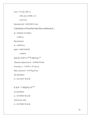
In table 5.1 conversion of ethanol and rate of reaction data is given. Unit of rate of reaction
is mol/(gm catalyst sec)
Table 5.1: rate of reaction and conversion data
r (total) 1/r
Ethanol
conversion
2.77216E-06 360729.1 0
2.24531E-06 445373.6 0.1
1.81423E-06 551197.8 0.2
1.45502E-06 687277 0.3
1.15111E-06 868729.7 0.4
8.90654E-07 1122770 0.5
8.31259E-07 1202994 0.525
4.67523E-07 2138934 0.7
2.9333E-07 3409130 0.8
From the graph (appendix A)
Area= 340000 unit
Weight of catalyst= 6579711 gm
= 6579.711 Kg
Bulk density =0.9333 gm/cc [8]
Volume = 6579.711/9333
= 7.049942 m3
Feed rate = 0.1382 Kmol/sec
= 0.1382 x 43.312
= 5.99 Kg/sec](https://image.slidesharecdn.com/deeequipmentdesign-161110173508/85/Diethyl-Ether-DEE-Equipments-Design-2-320.jpg)
![27
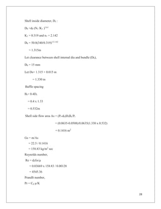
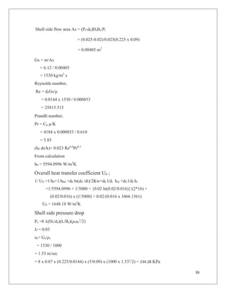
Calculation of shell side heat transfer, h0
Shell side heat transfer coefficient calculated here [11]
Tube pitch Pt =1.25d0
=1.25 x 0.0508
= 0.0635 m
Type of arrangement = Equilateral triangular
Equivalent diameter de = 1.1/d0 (Pt – 0.907 d0
2
)
= 1.1/0.0508[0.06352
– 0.907*0.0508 2
]
= 0.03663 m
Shell side mass flow rate m ;
∆H = m*Cp*∆T
Here coolant used is dowtherm Q because operating temperature is 523 K and dowtherm Q is
stable up to 603 K ( Properties from dowtherm Q product technical data)
Properties of dowtherm Q
Cp = 1811 J/Kg K
Viscosity µ = 1.28 x 10⁻³
pa.sec
Thermal conductivity K = 0.1156 W/mK
∆T= 60 K
m = 2445180.91/(1811 x 60)
= 22.5 Kg/s
Density = 927.6 Kg/ m3
Circulation rate qv = (22.5/927.6)
= 0.024 m3
/sec](https://image.slidesharecdn.com/deeequipmentdesign-161110173508/85/Diethyl-Ether-DEE-Equipments-Design-5-320.jpg)
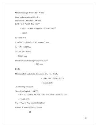
![29
= 1811 x 0.00128 / 0.1156
= 20.05
(h0 de/k)= 0.027 Re0.8
Pr0.3
From calculation
h0 = 150.50 W/m2
K
Overall heat transfer coefficient U0 ;
1/ U0 =1/h0+1/h0d +d0 ln(d0 /di)/2Kw+d0 l/di hid +d0 l/di hi
=1/150.50 + 1/5000 + {0.0508 ln(0.0508/0.04328)}/(2*16) +
(0.0508/0.04328)*(1/5000) + 0.0508/(0.04328 x 49.78)
U0 = 37.06 W/m2
K
Shell side pressure drop
Ps =8 Jf(Ds/de)(L/Bs)(ρsus
2
/2)
Jf = 0.07 from Jf vs Nre graph [11]
us= Gs/ρs
= 158.83 / 927.6
= 0.171 m/sec
= 8*0.07 x (1.330/0.03663) x (14/0.5323) x ( 985.728 x 0.0692
/2)
= 7335.7 Pa
Tube Side pressure drop
Pt =8 Jf(L/di)(ρsus
2
/2)
Jf = 0.03 from Jf vs Nre graph [11]
=8 x 0.03 x (14/0.04328) x (14.95 x 0.8022
)/2
= 0.3760672 KPa
Pressure drop across the bed
Blake – plummer equation
!
="
1.75(1 # $)%&
'
$*+,
"
P = 18.07 KPa](https://image.slidesharecdn.com/deeequipmentdesign-161110173508/85/Diethyl-Ether-DEE-Equipments-Design-7-320.jpg)
![30
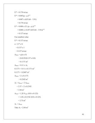
Total tube side pressure drop
Pt = 18.45 KPa
5.1.1 Mechanical Design of reactor
Shell and tube type reactor [6]
(a) Shell side
Material carbon steel - (Corrosion allowance- 3mm)
Number of passes – 1
Fluid – dowtherm Q
Working pressure – 0.3 N/mm2
Design pressure – 0.33 N/mm2
Inlet temperature – 25 0
C
Outlet temperature – 85 0
C
Segmental baffles (25% cut ) with tie rods and spacers
Maximum allowable stress - 80 N/mm2
Shell thickness; [6]
ts =PD/(2fJ+P)
= 0.33 x 1400/((2 x 80 x 0.85)+0.33) + 3 mm
= 6.38 mm
Nozzle thickness (diameter -75mm)
tn=PD/(2fJ-P)
= 0.33 x 75/( 2 x 80 – 0.33)
= 0.155 mm + 3 mm
= 3.155 mm
Head
Head thickness (th) = PCrW/2fJ
Crown radius = 1400 mm
Knuckle radius = 140 mm](https://image.slidesharecdn.com/deeequipmentdesign-161110173508/85/Diethyl-Ether-DEE-Equipments-Design-8-320.jpg)
![31
W=1/4(3+ (Rc/R1)1/2
)
= 1/4(3 + (1400/140)1/2
)
= 1.54
th = 0.33 x 1400 x 1.54 / (2 x 0.85 x 80) + 3mm
= 8.23mm
Transverse Baffles
Spacing between baffles= 0.4Ds
= 0.4 x 1.4
= 0.56m
Thickness of baffles = 5mm
Tube Side [6]
Tube and tube sheet material - stainless steel
Number of tubes – 340
Outside diameter – 50.8 mm
Length – 14m
Tube pitch - 0.0635m
Working pressure – 1.5 N/mm2
Design pressure – 1.65 N/mm2
Inlet temperature – 2500
C
Outlet temperature - 2500
C
Permissible stress – 74.5 N/mm2
tf =PD0/(2fJ+P)
= 1.65 x 50.8 / (2 x 74.5 x 0.85 + 1.65)
= 0.65 mm
No corrosion allowance, since the tubes are of stainless steel.
Design of Gasket and Bolt Size [6]
Gasket material – flat metal jacketed, asbestos fill (iron or soft steel)
Gasket factor, m= 3.75
Minimum design stress = 52.4 N/mm2](https://image.slidesharecdn.com/deeequipmentdesign-161110173508/85/Diethyl-Ether-DEE-Equipments-Design-9-320.jpg)
![33
Diameter of bolts = [(Am2/no. of bolts) x 3.14/4]1/2
= [(6652.203)/56 x (4/3.14)]1/2
=12.29 mm
Bolt area, Ab = 2 x 3.14 x YaGN/fa
= 2 x 3.14 x 52.48 x 1402.2 x 35 / 80
=202204.36 mm2
Pitch of bolts = 4.75*18
= 85.6 mm
Pitch circle dia.= (85.6*56)/3.14
=1526.62mm
Flange Thickness,
K= 1/[0.3+1.5WmhG/HG]
= 1/[0.3 + 1.5 x 532176.24 x 62.52136 /( 509382.1 X 1402.2)]
= 2.7
tf = G(p/kf)1/2
+c
= 1402.2 x (0.33/2.7/80) ½
+ 3
= 70.62 mm
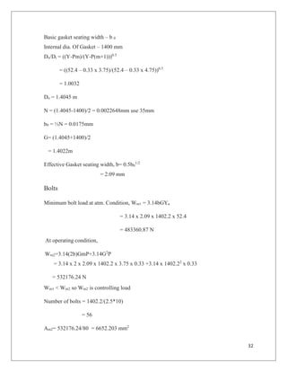
5.2 Heat exchanger Design
For heat exchanger tube side is waste water and shell side is cooling water is used. Here we
assume over all heat transfer coefficient (U) is 800 W/m2
K.In table 5.1 tube side and shell
side fluid inlet, outlet temperature and mass flowrate values given. [11]
Table 5.2: tube side and shell side flowrate and temperature
tube side shell side
flow rate(Kg/sec) 0.6714 6.12
inlet temperature(K) 401 308
outlet temperature(K) 310 318](https://image.slidesharecdn.com/deeequipmentdesign-161110173508/85/Diethyl-Ether-DEE-Equipments-Design-11-320.jpg)
![34
U=800 W/m2
K (assumed) [11]
LMTD= [(401-318)-(310-308)/ln((401-318)/(310-308))]
= 21.74 K
Q = 256454.44 J/sec
Q = UA(LMTD)
A=256454.44/(800 x 21.74)
= 14.74 m2
Material of construction (MOC) of tube = Stainless steel
Tube OD = 0.02 m
Tube ID = 0.016 m
Length of tube (L) = 5 m
Area of tube = ∏ x ID x L
= ∏ x (0.04328) x 5
= 0.303 m2
Total number of tube required
N = total area / area of tube
= 14.74/0.303
= 49
Tube side heat transfer coefficient
Cross section area = n x (∏/4) x ID2
= 49 x (∏/4) x (0.016)2
= 0.0098 m2
Velocity (u) = 0.000692/0.0098
= 0.0706 m/sec](https://image.slidesharecdn.com/deeequipmentdesign-161110173508/85/Diethyl-Ether-DEE-Equipments-Design-12-320.jpg)
![35
Density = 969.972 Kg/m3
Viscosity = 0.000345 Pa.sec
hi = 4200(1.35 + 0.02t)u0.8
/ID0.2
= 4200 (1.35 + 0.02 x 82.5) (0.0706)0.8
/(0.016)0.2
= 3466.1561
Shell side
Water flow rate = 6.12 Kg/sec
Pitch (P) = 1.25 x OD
= 1.25 x 0.02
= 0.025 m
Equivalent diameter de = 1.1/d0 (Pt – 0.907 d0
2
)
= 1.1/0.02[0.0252
– 0.907*0.022
]
= 0.0144 m
Shell inside diameter, Ds :
Db =d0 (Nt /K1 )1/n1
K1 = 0.319 and n1 = 2.142
Db = 0.02(49/0.319)1/2.142
= 0.21 m
Let clearance between shell internal dia and bundle (Db),
Db = 15 mm
Let Ds= 0.21 + 0.015 m
= 0.225 m
Baffle spacing
Bs= 0.4Ds
= 0.4 x 0.225 = 0.09 m](https://image.slidesharecdn.com/deeequipmentdesign-161110173508/85/Diethyl-Ether-DEE-Equipments-Design-13-320.jpg)
![37
Tube Side pressure drop
Pt = (8Jf(L/di) + 2.5)(ρtut
2
/2)
= ( 8 x 0.008 x (5/0.016) + 2.5)(969.69 x 0.0712
/2)
= 54.99 Pa
5.2.1 Mechanical Design for heat exchanger
Shell and tube type heat exchanger [6]
(a) Shell side
Material carbon steel - (Corrosion allowance- 3mm)
Number of passes – 1
Fluid – water
Working pressure – 0.4 N/mm2
Design pressure – 0.44 N/mm2
Inlet temperature – 25 0
C
Outlet temperature – 85 0
C
Segmental baffles (25% cut ) with tie rods and spacers
Shell thickness;
ts =PD/(2fJ+P)
= 0.44 x 300/((2 x 80 x 0.85)+0.44) + 3 mm
= 3.96 mm
Nozzle thickness (diameter -75mm)
tn=PD/(2fJ-P)
= 0.44 x 75/( 2 x 80 – 0.44)
= 0.21 mm + 3 mm
= 3.21 mm
Head
Head thickness (th) = PCrW/2fJ
Crown radius = 300 mm
Knuckle radius = 30 mm](https://image.slidesharecdn.com/deeequipmentdesign-161110173508/85/Diethyl-Ether-DEE-Equipments-Design-15-320.jpg)
![38
W=1/4(3+ (Rc/R1)1/2
)
= 1/4(3 + (300/30)1/2
)
= 1.54
th = 0.44 x 300 x 1.54 / (2 x 0.85 x 80) + 3mm
= 4.49 mm
Transverse Baffles
Spacing between baffles= 0.4Ds
= 0.4 x 0.3
= 0.12 m
Thickness of baffles = 5mm
Tube Side
Tube and tube sheet material - stainless steel
Number of tubes – 49
Outside diameter – 20 mm
Length – 5 m
Tube pitch - 0.025 m
Working pressure – 0.5 N/mm2
Design pressure – 0.55 N/mm2
Inlet temperature – 1280
C
Outlet temperature - 370
C
Permissible stress – 74.5 N/mm2
tf =PD0/(2fJ+P)
= 0.55 x 20 / (2 x 74.5 x 0.85 + 0.55)
= 0.086 mm
No corrosion allowance, since the tubes are of stainless steel.
Design of Gasket and Bolt Size [6]
Gasket material – flat metal jacketed, asbestos fill (iron or soft steel)
Gasket factor, m= 3.75](https://image.slidesharecdn.com/deeequipmentdesign-161110173508/85/Diethyl-Ether-DEE-Equipments-Design-16-320.jpg)
![40
Am2= 131402.52/80
= 1642.53 mm2
Diameter of bolts= [(Am2/no. of bolts) x 3.14/4]1/2
= [(1642.53)/12 x (4/3.14)]1/2
=13.19 mm
Bolt area, Ab = 2 x 3.14 x YaGN/fa
= 2 x 3.14 x 52.48 x 300.65 x 35 / 80
= 43350.36 mm2
Pitch of bolts = 4.75*18
= 85.6 mm
Pitch circle dia.= (85.6*12)/3.14
= 327.13 mm
Flange Thickness,
K= 1/[0.3+1.5WmhG/HG]
= 1/[0.3 + 1.5 x 131402.52 x 13.4 /( 31221.65 X 300.65)]
= 1.75
tf = G(p/kf)1/2
+c
= 300.65 x (0.44/1.75/80) ½
+ 3
= 23.99 mm
Use 24 mm
5.3 Distillation column Design:
Operating pressure at top = 1 atm = 101.325 KPa
Reflux ratio = 3.49
Number of plates = 40
Distillation molar rate D = 0.0327 Kmol/sec
Liquid molar rate L= D x R
= 0.0327 x 3.49
= 0.114 Kmol/sec](https://image.slidesharecdn.com/deeequipmentdesign-161110173508/85/Diethyl-Ether-DEE-Equipments-Design-18-320.jpg)
![41
Vapor molar rate = D x (R + 1)
= 0.0327 x (3.49 + 1)
= 0.1468 Kmol/sec
Vapor density ρv = 3.91 Kg/m3
Liquid density ρl = 653.64 Kg/m3
Vapor and liquid flowrate is given in table 5.2
Table 5.3: vapor and liquid flowrate
vapor liquid
molar flow rate 0.1468 0.1141
mass rate 10.8649 8.4451
vol. rate 2.7750 0.0129
Vload = Q [ρv / (ρl - ρv)]0.5
= 2.77 [ 3.91/(653.64 – 3.91)]0.5
= 0.2154 m3
/sec
q = 0.0129 m3
/sec
Single pass
Dt = 1.7 m (from graph of Vload and liquid flowrate)
System factor S = 1
Flooding factor = 0.8 ( 80 % flooding)
Flow path length L = 0.75 x Dt / number of pass
= 0.75 x 1.7 / 1
= 1.275 m
C* = 0.125
C = S x C*
= 1 x 0.125
= 0.125
Aamin = [ vapor load + 1.36qL]/ (C x F)
= [ 0.2154 + 1.36 x 0.0129 x 1.275 ]/(0.125 x 0.8) = 2.37 m2](https://image.slidesharecdn.com/deeequipmentdesign-161110173508/85/Diethyl-Ether-DEE-Equipments-Design-19-320.jpg)
![44
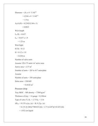
∆Pdry = K2Vn
2
(ρv /ρl)
= 13.6 (6.692
)(3.91/653.64)
= 3.65 cm liquid
∆Pt = ∆Pdry + 55.4(q/Lw)0.67
+ 0.04hw
= 3.65 + 55.4(0.0129/1.25)0.67
+ 0.04 x 50
= 8.44 cm liquid
= 0.076 psi
Hde = 55.4(q/Lw)0.67
+ 0.1 hw + (∆Pt + 1.66)( ρl / (ρl - ρv))
= 55.4(0.0129/1.25)0.67
+ 0.1 x 50 + (8.44 + 1.66)(653.64/(653.64-3.91))
= 17.96 cm liquid < 0.6 TS
%Flooding = Vload / (0.78ATC)
= 0.2154 / (0.78 x 2.84 x0.125)
= 77.60%
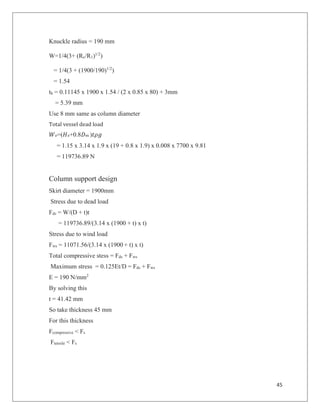
5.3.1 Mechanical design of distillation column
Mechanical design of distillation column including support. [14]
Operating pressure = 101.325 Kpa
Design pressure = 1.1 x 101.325 = 111.45 Kpa = 0.11145 N/mm2
Design temperature = 423 K
MOC = carbon steel
Diameter = 1900 mm
Thickness of the column
tc = PD/(2fJ - P)
= 0.44 x 300/((2 x 80 x 0.85) - 0.44) + 3 mm
= 3.065 mm
But take 8mm
Head
Torispherical head [6]
Head thickness (th) = PCrW/2fJ
Crown radius = 1900 mm](https://image.slidesharecdn.com/deeequipmentdesign-161110173508/85/Diethyl-Ether-DEE-Equipments-Design-22-320.jpg)

This document provides a detailed design of a fixed bed catalytic reactor, including specifications for temperature, catalyst properties, and mechanical design calculations. Key parameters such as mass and superficial velocity of feed gas, catalyst volume, and heat transfer coefficients are extensively discussed, along with pressure drops and thermal design specifics. Additionally, it includes calculations for tube and shell design, materials used, and operational parameters for the heat exchanger.


