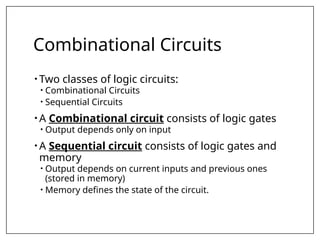
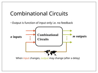
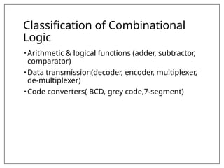
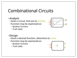
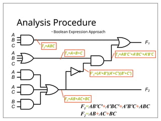
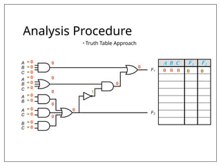
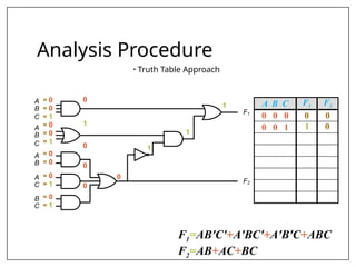
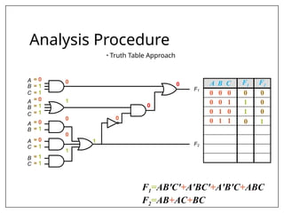
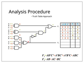
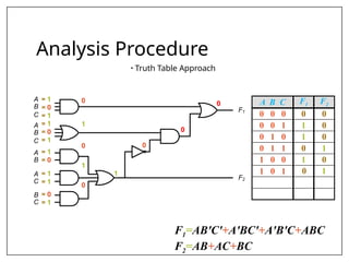
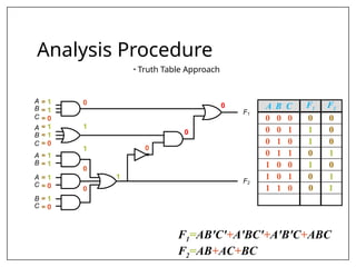
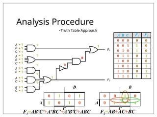
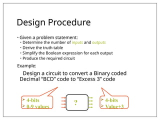
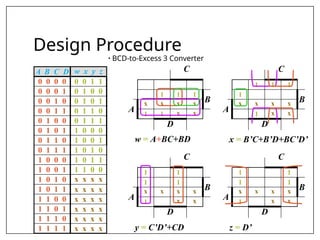
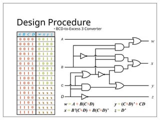
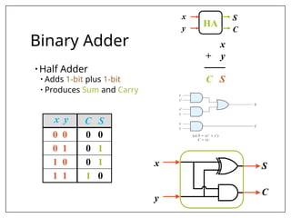
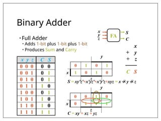
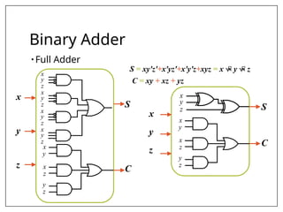
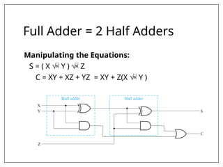
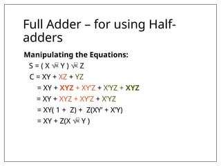
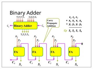
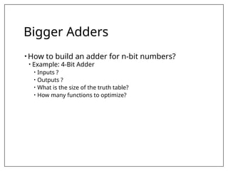
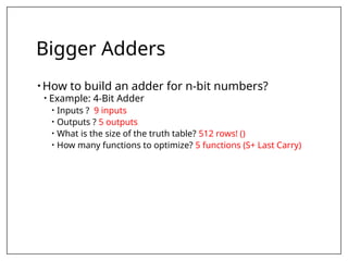
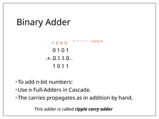
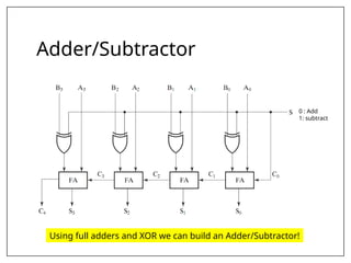
LOGIC AND SEQUENTIAL CIRCUIT
DESIGN
SPRING 2024
CHAPTER 4 – COMBINATIONAL LOGIC
2
Combinational Circuits
• Two classes of logic circuits:
• Combinational Circuits
• Sequential Circuits
• A Combinational circuit consists of logic gates
• Output depends only on input
• A Sequential circuit consists of logic gates and
memory
• Output depends on current inputs and previous ones
(stored in memory)
• Memory defines the state of the circuit.
Combinational Circuits
• Output is function of input only i.e. no feedback
When input changes, output may change (after a delay)
•
•
•
•
•
•
n inputs m outputs
Combinational
Circuits

Classification of Combinational
Logic
• Arithmetic & logical functions (adder, subtractor,
comparator)
• Data transmission(decoder, encoder, multiplexer,
de-multiplexer)
• Code converters( BCD, grey code,7-segment)
Combinational Circuits
• Analysis
• Given a circuit, find out its function
• Function may be expressed as:
• Boolean function
• Truth table
• Design
• Given a desired function, determine its circuit
• Function may be expressed as:
• Boolean function
• Truth table
C
B
A
C
B
A
B
A
C
A
C
B
F1
F2
?
?
?
Analysis Procedure
• Boolean Expression Approach
C
B
A
C
B
A
B
A
C
A
C
B
F1
F2
T2=ABC
T1=A+B+C
F2=AB+AC+BC
F’2=(A’+B’)(A’+C’)(B’+C’)
T3=AB'C'+A'BC'+A'B'C
F1=AB'C'+A'BC'+A'B'C+ABC
F2=AB+AC+BC
C
B
A
C
B
A
B
A
C
A
C
B
F1
F2
Analysis Procedure
• Truth Table Approach
A B C F1 F2
0 0 0
= 0
= 0
= 0
= 0
= 0
= 0
= 0
= 0
= 0
= 0
= 0
= 0
0
0
0
0
0
0
1
0
0
0 0
C
B
A
C
B
A
B
A
C
A
C
B
F1
F2
Analysis Procedure
• Truth Table Approach
0
1
= 0
= 0
= 1
= 0
= 0
= 1
= 0
= 0
= 0
= 1
= 0
= 1
0
1
0
0
0
A B C F1 F2
0 0 0 0 0
0 0 1 1 0
1
1
F1=AB'C'+A'BC'+A'B'C+ABC
F2=AB+AC+BC
C
B
A
C
B
A
B
A
C
A
C
B
F1
F2
Analysis Procedure
• Truth Table Approach
0
1
0
1
0
0
0
1
1 A B C F1 F2
0 0 0 0 0
0 0 1 1 0
0 1 0 1 0
= 0
= 1
= 0
= 0
= 1
= 0
= 0
= 1
= 0
= 0
= 1
= 0
F1=AB'C'+A'BC'+A'B'C+ABC
F2=AB+AC+BC
C
B
A
C
B
A
B
A
C
A
C
B
F1
F2
Analysis Procedure
• Truth Table Approach
0
0
0 A B C F1 F2
0 0 0 0 0
0 0 1 1 0
0 1 0 1 0
0 1 1 0 1
= 0
= 1
= 1
= 0
= 1
= 1
= 0
= 1
= 0
= 1
= 1
= 1
0
1
0
0
1
1
F1=AB'C'+A'BC'+A'B'C+ABC
F2=AB+AC+BC
C
B
A
C
B
A
B
A
C
A
C
B
F1
F2
Analysis Procedure
• Truth Table Approach
1
1
1
0
A B C F1 F2
0 0 0 0 0
0 0 1 1 0
0 1 0 1 0
0 1 1 0 1
1 0 0 1 0
= 1
= 0
= 0
= 1
= 0
= 0
= 1
= 0
= 1
= 0
= 0
= 0
0
1
0
0
0
F1=AB'C'+A'BC'+A'B'C+ABC
F2=AB+AC+BC
C
B
A
C
B
A
B
A
C
A
C
B
F1
F2
Analysis Procedure
• Truth Table Approach
= 1
= 0
= 1
= 1
= 0
= 1
= 1
= 0
= 1
= 1
= 0
= 1
0
1
0
1
0
0
0
0
1
A B C F1 F2
0 0 0 0 0
0 0 1 1 0
0 1 0 1 0
0 1 1 0 1
1 0 0 1 0
1 0 1 0 1
F1=AB'C'+A'BC'+A'B'C+ABC
F2=AB+AC+BC
C
B
A
C
B
A
B
A
C
A
C
B
F1
F2
Analysis Procedure
• Truth Table Approach
0
0
0
1
0 1
= 1
= 1
= 0
= 1
= 1
= 0
= 1
= 1
= 1
= 0
= 1
= 0
0
1
1
0
0
A B C F1 F2
0 0 0 0 0
0 0 1 1 0
0 1 0 1 0
0 1 1 0 1
1 0 0 1 0
1 0 1 0 1
1 1 0
F1=AB'C'+A'BC'+A'B'C+ABC
F2=AB+AC+BC
C
B
A
C
B
A
B
A
C
A
C
B
F1
F2
Analysis Procedure
• Truth Table Approach
0
0
1
1
= 1
= 1
= 1
= 1
= 1
= 1
= 1
= 1
= 1
= 1
= 1
= 1
1
1
1
1
1
A B C F1 F2
0 0 0 0 0
0 0 1 1 0
0 1 0 1 0
0 1 1 0 1
1 0 0 1 0
1 0 1 0 1
1 1 0 0 1
1 1 1 1 1
B
0 1 0 1
A 1 0 1 0
C
B
0 0 1 0
A 0 1 1 1
C
F1=AB'C'+A'BC'+A'B'C+ABC F2=AB+AC+BC
Design Procedure
• Given a problem statement:
• Determine the number of inputs and outputs
• Derive the truth table
• Simplify the Boolean expression for each output
• Produce the required circuit
Example:
Design a circuit to convert a Binary coded
Decimal “BCD” code to “Excess 3” code
 4-bits
 0-9 values
 4-bits
 Value+3
?
Design Procedure
• BCD-to-Excess 3 Converter
A B C D w x y z
0 0 0 0 0 0 1 1
0 0 0 1 0 1 0 0
0 0 1 0 0 1 0 1
0 0 1 1 0 1 1 0
0 1 0 0 0 1 1 1
0 1 0 1 1 0 0 0
0 1 1 0 1 0 0 1
0 1 1 1 1 0 1 0
1 0 0 0 1 0 1 1
1 0 0 1 1 1 0 0
1 0 1 0 x x x x
1 0 1 1 x x x x
1 1 0 0 x x x x
1 1 0 1 x x x x
1 1 1 0 x x x x
1 1 1 1 x x x x
C
1 1 1
B
A
x x x x
1 1 x x
D
C
1 1 1
1
B
A
x x x x
1 x x
D
C
1 1
1 1
B
A
x x x x
1 x x
D
C
1 1
1 1
B
A
x x x x
1 x x
D
w = A+BC+BD x = B’C+B’D+BC’D’
y = C’D’+CD z = D’
Design Procedure
• BCD-to-Excess 3 Converter
A B C D w x y z
0 0 0 0 0 0 1 1
0 0 0 1 0 1 0 0
0 0 1 0 0 1 0 1
0 0 1 1 0 1 1 0
0 1 0 0 0 1 1 1
0 1 0 1 1 0 0 0
0 1 1 0 1 0 0 1
0 1 1 1 1 0 1 0
1 0 0 0 1 0 1 1
1 0 0 1 1 1 0 0
1 0 1 0 x x x x
1 0 1 1 x x x x
1 1 0 0 x x x x
1 1 0 1 x x x x
1 1 1 0 x x x x
1 1 1 1 x x x x
w
x
D
C
z
y
B
A
w = A + B(C+D)
x = B’(C+D) + B(C+D)’
y = (C+D)’ + CD
z = D’
Seven-Segment converter
• Seven-Segment Display
• A seven-segment display is digital readout found
in electronic devices like clocks, TVs, etc.
• Made of seven light-emitting diodes (LED) segments;
each segment is controlled separately.
Seven-Segment converter a
b
c
g
e
d
f
?
w
x
y
z
a
b
c
d
e
f
g
w x y z a b c d e f g
0 0 0 0 1 1 1 1 1 1 0
0 0 0 1 0 1 1 0 0 0 0
0 0 1 0 1 1 0 1 1 0 1
0 0 1 1 1 1 1 1 0 0 1
0 1 0 0 0 1 1 0 0 1 1
0 1 0 1 1 0 1 1 0 1 1
0 1 1 0 1 0 1 1 1 1 1
0 1 1 1 1 1 1 0 0 0 0
1 0 0 0 1 1 1 1 1 1 1
1 0 0 1 1 1 1 1 0 1 1
1 0 1 0 x x x x x x x
1 0 1 1 x x x x x x x
1 1 0 0 x x x x x x x
1 1 0 1 x x x x x x x
1 1 1 0 x x x x x x x
1 1 1 1 x x x x x x x
y
1 1 1
1 1 1
x
w
x x x x
1 1 x x
z
BCD code
a = w + y + xz + x’z’ b = . . .
c = . . .
d = . . .
Binary Adder
• Half Adder
• Adds 1-bit plus 1-bit
• Produces Sum and Carry
HA
x
y
S
C
x y C S
0 0 0 0
0 1 0 1
1 0 0 1
1 1 1 0
x
+ y
───
C S
x
y
S
C
Binary Adder
• Full Adder
• Adds 1-bit plus 1-bit plus 1-bit
• Produces Sum and Carry
x y z C S
0 0 0 0 0
0 0 1 0 1
0 1 0 0 1
0 1 1 1 0
1 0 0 0 1
1 0 1 1 0
1 1 0 1 0
1 1 1 1 1
x
+ y
+ z
───
C S
FA
x
y
z
S
C
y
0 1 0 1
x 1 0 1 0
z
y
0 0 1 0
x 0 1 1 1
z
S = xy'z'+x'yz'+x'y'z+xyz = x  y  z
C = xy + xz + yz
Binary Adder
• Full Adder
x
y
z
S
C
x
y
x
z
y
z
x
y
z
x
y
z
x
y
z
x
y
z
x
y
z
x
y
z
x
y
x
z
y
z
S
C
S = xy'z'+x'yz'+x'y'z+xyz = x  y  z
C = xy + xz + yz
Full Adder = 2 Half Adders
Manipulating the Equations:
S = ( X  Y )  Z
C = XY + XZ + YZ = XY + Z(X  Y )
Full Adder – for using Half-
adders
Manipulating the Equations:
S = ( X  Y )  Z
C = XY + XZ + YZ
= XY + XYZ + XY’Z + X’YZ + XYZ
= XY + XYZ + XY’Z + X’YZ
= XY( 1 + Z) + Z(XY’ + X’Y)
= XY + Z(X  Y )
Binary Adder
c3 c2 c1 .
+ x3 x2 x1 x0
+ y3 y2 y1 y0
────────
Cy S3 S2 S1 S0
FA
x3 x2 x1 x0
FA
FA
FA
y3 y2 y1 y0
S3 S2 S1 S0
C4 C3 C2 C1
0
Binary Adder
x3x2x1x0 y3y2y1y0
S3S2S1S0
C0
Cy
Carry
Propagate
Addition
Bigger Adders
• How to build an adder for n-bit numbers?
• Example: 4-Bit Adder
• Inputs ?
• Outputs ?
• What is the size of the truth table?
• How many functions to optimize?
Bigger Adders
• How to build an adder for n-bit numbers?
• Example: 4-Bit Adder
• Inputs ? 9 inputs
• Outputs ? 5 outputs
• What is the size of the truth table? 512 rows! ()
• How many functions to optimize? 5 functions (S+ Last Carry)
Binary Adder
1 0 0 0
0 1 0 1
+ 0 1 1 0
1 0 1 1
• To add n-bit numbers:
• Use n Full-Adders in Cascade.
• The carries propagates as in addition by hand.
Carry in
This adder is called ripple carry adder
Binary Subtractor
• Half Subtractor
A logic circuit which is used for subtracting one
single bit binary number from another single bit
binary number is called half subtractor.
Binary Subtractor
• Half Subtractor
S.No
INPUT OUTPUT
A B DIFF BORR
1. 0 0 0 0
2. 0 1 1 1
3. 1 0 1 0
4. 1 1 0 0
Binary Subtractor
• Full Subtractor
The Full subtractor is a combinational circuit
which is used to perform subtraction of three
bits.
Binary Subtractor
• Full Subtractor
S.N
o
INPUT OUTPUT
A B C DIFF BORR
1. 0 0 0 0 0
2. 0 0 1 1 1
3. 0 1 0 1 1
4. 0 1 1 0 1
5. 1 0 0 1 0
6. 1 0 1 0 0
7. 1 1 0 0 0
8. 1 1 1 1 1
Binary Subtractor (Your
Practice)
• Derive simplified Boolean expressions for Half
Subtractor and Full Subtractor.
Subtraction (2’s Complement)
• How to build a subtractor using 2’s complement?
Subtraction (2’s Complement)
• How to build a subtractor using 2’s complement?
1
S = A + ( -B)
Adder/Subtractor
• How to build a circuit that performs both
addition and subtraction?
Adder/Subtractor
Using full adders and XOR we can build an Adder/Subtractor!
0 : Add
1: subtract

Lecture-5a - Half and Full Adxcccder.pptx

  • 1.
    LOGIC AND SEQUENTIALCIRCUIT DESIGN SPRING 2024
  • 2.
    CHAPTER 4 –COMBINATIONAL LOGIC 2
  • 3.
    Combinational Circuits • Twoclasses of logic circuits: • Combinational Circuits • Sequential Circuits • A Combinational circuit consists of logic gates • Output depends only on input • A Sequential circuit consists of logic gates and memory • Output depends on current inputs and previous ones (stored in memory) • Memory defines the state of the circuit.
  • 4.
    Combinational Circuits • Outputis function of input only i.e. no feedback When input changes, output may change (after a delay) • • • • • • n inputs m outputs Combinational Circuits 
  • 5.
    Classification of Combinational Logic •Arithmetic & logical functions (adder, subtractor, comparator) • Data transmission(decoder, encoder, multiplexer, de-multiplexer) • Code converters( BCD, grey code,7-segment)
  • 6.
    Combinational Circuits • Analysis •Given a circuit, find out its function • Function may be expressed as: • Boolean function • Truth table • Design • Given a desired function, determine its circuit • Function may be expressed as: • Boolean function • Truth table C B A C B A B A C A C B F1 F2 ? ? ?
  • 7.
    Analysis Procedure • BooleanExpression Approach C B A C B A B A C A C B F1 F2 T2=ABC T1=A+B+C F2=AB+AC+BC F’2=(A’+B’)(A’+C’)(B’+C’) T3=AB'C'+A'BC'+A'B'C F1=AB'C'+A'BC'+A'B'C+ABC F2=AB+AC+BC
  • 8.
    C B A C B A B A C A C B F1 F2 Analysis Procedure • TruthTable Approach A B C F1 F2 0 0 0 = 0 = 0 = 0 = 0 = 0 = 0 = 0 = 0 = 0 = 0 = 0 = 0 0 0 0 0 0 0 1 0 0 0 0
  • 9.
    C B A C B A B A C A C B F1 F2 Analysis Procedure • TruthTable Approach 0 1 = 0 = 0 = 1 = 0 = 0 = 1 = 0 = 0 = 0 = 1 = 0 = 1 0 1 0 0 0 A B C F1 F2 0 0 0 0 0 0 0 1 1 0 1 1 F1=AB'C'+A'BC'+A'B'C+ABC F2=AB+AC+BC
  • 10.
    C B A C B A B A C A C B F1 F2 Analysis Procedure • TruthTable Approach 0 1 0 1 0 0 0 1 1 A B C F1 F2 0 0 0 0 0 0 0 1 1 0 0 1 0 1 0 = 0 = 1 = 0 = 0 = 1 = 0 = 0 = 1 = 0 = 0 = 1 = 0 F1=AB'C'+A'BC'+A'B'C+ABC F2=AB+AC+BC
  • 11.
    C B A C B A B A C A C B F1 F2 Analysis Procedure • TruthTable Approach 0 0 0 A B C F1 F2 0 0 0 0 0 0 0 1 1 0 0 1 0 1 0 0 1 1 0 1 = 0 = 1 = 1 = 0 = 1 = 1 = 0 = 1 = 0 = 1 = 1 = 1 0 1 0 0 1 1 F1=AB'C'+A'BC'+A'B'C+ABC F2=AB+AC+BC
  • 12.
    C B A C B A B A C A C B F1 F2 Analysis Procedure • TruthTable Approach 1 1 1 0 A B C F1 F2 0 0 0 0 0 0 0 1 1 0 0 1 0 1 0 0 1 1 0 1 1 0 0 1 0 = 1 = 0 = 0 = 1 = 0 = 0 = 1 = 0 = 1 = 0 = 0 = 0 0 1 0 0 0 F1=AB'C'+A'BC'+A'B'C+ABC F2=AB+AC+BC
  • 13.
    C B A C B A B A C A C B F1 F2 Analysis Procedure • TruthTable Approach = 1 = 0 = 1 = 1 = 0 = 1 = 1 = 0 = 1 = 1 = 0 = 1 0 1 0 1 0 0 0 0 1 A B C F1 F2 0 0 0 0 0 0 0 1 1 0 0 1 0 1 0 0 1 1 0 1 1 0 0 1 0 1 0 1 0 1 F1=AB'C'+A'BC'+A'B'C+ABC F2=AB+AC+BC
  • 14.
    C B A C B A B A C A C B F1 F2 Analysis Procedure • TruthTable Approach 0 0 0 1 0 1 = 1 = 1 = 0 = 1 = 1 = 0 = 1 = 1 = 1 = 0 = 1 = 0 0 1 1 0 0 A B C F1 F2 0 0 0 0 0 0 0 1 1 0 0 1 0 1 0 0 1 1 0 1 1 0 0 1 0 1 0 1 0 1 1 1 0 F1=AB'C'+A'BC'+A'B'C+ABC F2=AB+AC+BC
  • 15.
    C B A C B A B A C A C B F1 F2 Analysis Procedure • TruthTable Approach 0 0 1 1 = 1 = 1 = 1 = 1 = 1 = 1 = 1 = 1 = 1 = 1 = 1 = 1 1 1 1 1 1 A B C F1 F2 0 0 0 0 0 0 0 1 1 0 0 1 0 1 0 0 1 1 0 1 1 0 0 1 0 1 0 1 0 1 1 1 0 0 1 1 1 1 1 1 B 0 1 0 1 A 1 0 1 0 C B 0 0 1 0 A 0 1 1 1 C F1=AB'C'+A'BC'+A'B'C+ABC F2=AB+AC+BC
  • 16.
    Design Procedure • Givena problem statement: • Determine the number of inputs and outputs • Derive the truth table • Simplify the Boolean expression for each output • Produce the required circuit Example: Design a circuit to convert a Binary coded Decimal “BCD” code to “Excess 3” code  4-bits  0-9 values  4-bits  Value+3 ?
  • 17.
    Design Procedure • BCD-to-Excess3 Converter A B C D w x y z 0 0 0 0 0 0 1 1 0 0 0 1 0 1 0 0 0 0 1 0 0 1 0 1 0 0 1 1 0 1 1 0 0 1 0 0 0 1 1 1 0 1 0 1 1 0 0 0 0 1 1 0 1 0 0 1 0 1 1 1 1 0 1 0 1 0 0 0 1 0 1 1 1 0 0 1 1 1 0 0 1 0 1 0 x x x x 1 0 1 1 x x x x 1 1 0 0 x x x x 1 1 0 1 x x x x 1 1 1 0 x x x x 1 1 1 1 x x x x C 1 1 1 B A x x x x 1 1 x x D C 1 1 1 1 B A x x x x 1 x x D C 1 1 1 1 B A x x x x 1 x x D C 1 1 1 1 B A x x x x 1 x x D w = A+BC+BD x = B’C+B’D+BC’D’ y = C’D’+CD z = D’
  • 18.
    Design Procedure • BCD-to-Excess3 Converter A B C D w x y z 0 0 0 0 0 0 1 1 0 0 0 1 0 1 0 0 0 0 1 0 0 1 0 1 0 0 1 1 0 1 1 0 0 1 0 0 0 1 1 1 0 1 0 1 1 0 0 0 0 1 1 0 1 0 0 1 0 1 1 1 1 0 1 0 1 0 0 0 1 0 1 1 1 0 0 1 1 1 0 0 1 0 1 0 x x x x 1 0 1 1 x x x x 1 1 0 0 x x x x 1 1 0 1 x x x x 1 1 1 0 x x x x 1 1 1 1 x x x x w x D C z y B A w = A + B(C+D) x = B’(C+D) + B(C+D)’ y = (C+D)’ + CD z = D’
  • 19.
    Seven-Segment converter • Seven-SegmentDisplay • A seven-segment display is digital readout found in electronic devices like clocks, TVs, etc. • Made of seven light-emitting diodes (LED) segments; each segment is controlled separately.
  • 20.
    Seven-Segment converter a b c g e d f ? w x y z a b c d e f g wx y z a b c d e f g 0 0 0 0 1 1 1 1 1 1 0 0 0 0 1 0 1 1 0 0 0 0 0 0 1 0 1 1 0 1 1 0 1 0 0 1 1 1 1 1 1 0 0 1 0 1 0 0 0 1 1 0 0 1 1 0 1 0 1 1 0 1 1 0 1 1 0 1 1 0 1 0 1 1 1 1 1 0 1 1 1 1 1 1 0 0 0 0 1 0 0 0 1 1 1 1 1 1 1 1 0 0 1 1 1 1 1 0 1 1 1 0 1 0 x x x x x x x 1 0 1 1 x x x x x x x 1 1 0 0 x x x x x x x 1 1 0 1 x x x x x x x 1 1 1 0 x x x x x x x 1 1 1 1 x x x x x x x y 1 1 1 1 1 1 x w x x x x 1 1 x x z BCD code a = w + y + xz + x’z’ b = . . . c = . . . d = . . .
  • 21.
    Binary Adder • HalfAdder • Adds 1-bit plus 1-bit • Produces Sum and Carry HA x y S C x y C S 0 0 0 0 0 1 0 1 1 0 0 1 1 1 1 0 x + y ─── C S x y S C
  • 22.
    Binary Adder • FullAdder • Adds 1-bit plus 1-bit plus 1-bit • Produces Sum and Carry x y z C S 0 0 0 0 0 0 0 1 0 1 0 1 0 0 1 0 1 1 1 0 1 0 0 0 1 1 0 1 1 0 1 1 0 1 0 1 1 1 1 1 x + y + z ─── C S FA x y z S C y 0 1 0 1 x 1 0 1 0 z y 0 0 1 0 x 0 1 1 1 z S = xy'z'+x'yz'+x'y'z+xyz = x  y  z C = xy + xz + yz
  • 23.
    Binary Adder • FullAdder x y z S C x y x z y z x y z x y z x y z x y z x y z x y z x y x z y z S C S = xy'z'+x'yz'+x'y'z+xyz = x  y  z C = xy + xz + yz
  • 24.
    Full Adder =2 Half Adders Manipulating the Equations: S = ( X  Y )  Z C = XY + XZ + YZ = XY + Z(X  Y )
  • 25.
    Full Adder –for using Half- adders Manipulating the Equations: S = ( X  Y )  Z C = XY + XZ + YZ = XY + XYZ + XY’Z + X’YZ + XYZ = XY + XYZ + XY’Z + X’YZ = XY( 1 + Z) + Z(XY’ + X’Y) = XY + Z(X  Y )
  • 26.
    Binary Adder c3 c2c1 . + x3 x2 x1 x0 + y3 y2 y1 y0 ──────── Cy S3 S2 S1 S0 FA x3 x2 x1 x0 FA FA FA y3 y2 y1 y0 S3 S2 S1 S0 C4 C3 C2 C1 0 Binary Adder x3x2x1x0 y3y2y1y0 S3S2S1S0 C0 Cy Carry Propagate Addition
  • 27.
    Bigger Adders • Howto build an adder for n-bit numbers? • Example: 4-Bit Adder • Inputs ? • Outputs ? • What is the size of the truth table? • How many functions to optimize?
  • 28.
    Bigger Adders • Howto build an adder for n-bit numbers? • Example: 4-Bit Adder • Inputs ? 9 inputs • Outputs ? 5 outputs • What is the size of the truth table? 512 rows! () • How many functions to optimize? 5 functions (S+ Last Carry)
  • 29.
    Binary Adder 1 00 0 0 1 0 1 + 0 1 1 0 1 0 1 1 • To add n-bit numbers: • Use n Full-Adders in Cascade. • The carries propagates as in addition by hand. Carry in This adder is called ripple carry adder
  • 30.
    Binary Subtractor • HalfSubtractor A logic circuit which is used for subtracting one single bit binary number from another single bit binary number is called half subtractor.
  • 31.
    Binary Subtractor • HalfSubtractor S.No INPUT OUTPUT A B DIFF BORR 1. 0 0 0 0 2. 0 1 1 1 3. 1 0 1 0 4. 1 1 0 0
  • 32.
    Binary Subtractor • FullSubtractor The Full subtractor is a combinational circuit which is used to perform subtraction of three bits.
  • 33.
    Binary Subtractor • FullSubtractor S.N o INPUT OUTPUT A B C DIFF BORR 1. 0 0 0 0 0 2. 0 0 1 1 1 3. 0 1 0 1 1 4. 0 1 1 0 1 5. 1 0 0 1 0 6. 1 0 1 0 0 7. 1 1 0 0 0 8. 1 1 1 1 1
  • 34.
    Binary Subtractor (Your Practice) •Derive simplified Boolean expressions for Half Subtractor and Full Subtractor.
  • 35.
    Subtraction (2’s Complement) •How to build a subtractor using 2’s complement?
  • 36.
    Subtraction (2’s Complement) •How to build a subtractor using 2’s complement? 1 S = A + ( -B)
  • 37.
    Adder/Subtractor • How tobuild a circuit that performs both addition and subtraction?
  • 38.
    Adder/Subtractor Using full addersand XOR we can build an Adder/Subtractor! 0 : Add 1: subtract

Editor's Notes

  • #21 A combinational circuit that performs the addition of two bits is called a half adder,
  • #22 One that performs the addition of three bits (two significant bits and a previous carry) is called full adder
  • #26 Also called Ripple carry adder