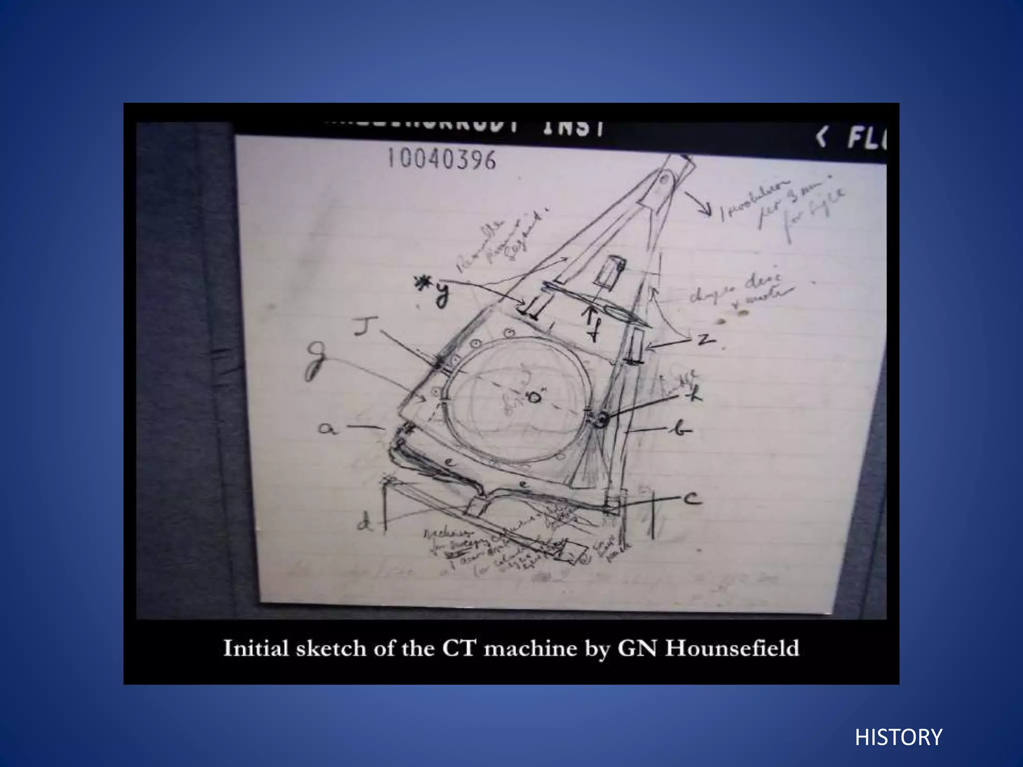
COMPUTED TOMOGRAPHY
FARAKATH KHAN
GUIDED BY- TATU JOY
Introduction
History
Components of CT
Detectors
Generations
Scanning parameters
Patient preparation
Indications
Advantages
limitations
Artifacts
TOMOGRAPHY
It is a generic term formed from the Greek words tomos meaning
“slice” or “section” and graphia meaning “picture” or “describing” that
was adopted in 1962 by the international commission on radiological
units and measurements to describe all forms of body section
radiography.
INTRODUCTION
CONVENTIONAL TOMOGRAPHY :
It is a special x ray technique that enables visualization of
a section of the patients anatomy by blurring regions of the
patients anatomy above and below the section of interest.
INTRODUCTION
Linear tomogram of TMJ
PARASITE LINES
INTRODUCTION
COMPUTED TOMOGRAPHY (computerized axial
transverse scanning)
It is a radiographic technique that blends the concept of thin layer
radiography (tomography) with computer synthesis. Alan Cormack in
1960s – image
reconstruction
Godfrey Hounsfield
in 1972 – imaging
technique
120 – 140 kVp
200 – 800 mA
INTRODUCTION
CT HISTORY
First test images 1967
First clinical image 1971
First commercial scanner 1972
Sir Godfrey Newbold Hounsfield
CT brain 1972-73
Noble prize 1979
HISTORY
HISTORY
HISTORY
HISTORY
HISTORY
Siretom scanner
CT COMPUTERS
Old Mainframe Computers Too Expensive And Bulky
HISTORY
Components of CT system
• The scanning unit, i.e. the gantry, with tube
and detector system
• The patient table
• The image processor for image reconstruction
• The console
Scanning unit (gantry)
GANTRY DIMENSIONS
Height-2-2.5 m
Width-2-3 m
Depth-0.5-1 m
Weight-2000 kg
GANTRY
X RAY TUBE
Focal spot size 0.6*1.2 sq.mm
(small focal spot – high resolution images with thin slice)
SHIELDING
Grids, collimators and filters.
Aperture in gantry-70 cm diameter
Table-for patient movements
Patient alignment lights-high intensity halogens, low intensity
lasers.
CONSOLE
DETECTORS
Incident x ray
Electric signals
Digital pulses
IMAGE RECEPTORS
DIRECT EXPOSURE
FILM
SCREEN FILM
ELECTRONIC
SENSORS
IOPA
BITEWING
OCCLUSSAL
EXTRAORAL
PANORAMIC
CCD
CMOS
FLAT
PANEL
PSP
PLATE
A,B,C,D,E
SPEED
• Types
Sodium iodide
Calcium fluoride
Bismuth germinate
Scintillation detectors
(sodium iodide, caesium
iodide)
DETECTORS
Gas ionization
(xenon gas 20-30 atm)
Multi row detector
Adaptive array detector
Detector
• Sequential CT
• Spiral CT
CT scanner consists of a radiographic tube that emits a finely
collimated, fan shaped X ray beam directed to a series of
scintillation detectors or ionization chambers
GENERATIONS
SCANNER PARAMETERS
• COLLIMATION
• INCREMENT
• PITCH
• ROTATION TIME
• mAs
COLLIMATION
Source collimator
Detector collimator
Collimation determine the quality of slice profile
From the data volume of the multislice scanner images
can be reconstructed with slice thickness equal to or
larger than detector collimation.
SCANNER PARAMETER
INCREMENT
SCANNER PARAMETER
The distance between images reconstructed from a data volume .
If appropriate increment is used overlapping images can be reconstructed
Clinically useful overlap is 30-50%
PITCH
PITCH = TABLE FEED PER ROTATION / IMAGE THICKNESS
SCANNER PARAMETER
Larger table feed, faster scanning (few rotation) but image quality impaired
ROTATION TIME
Is the time interval needed for a complete 360 degree
rotation of tube detector system around the patient.
Ultra modern Ct system-0.4 seconds for one rotation
mAs
mAs value is the product of tube current and rotation
time.
The selected mAs and tube voltage determine the
dose.
SCANNER PARAMETER
Patient preparation – CT Head and Neck
Fasting 4 hrs prior to scan, remove outdoor
coats.
Radiation dose
INHERENT DESIGN
• Type Of X Ray
Tube
• Collimation
• Beam Splitting
Device
• Tube Patient –
Detector Distance
RADIOGRAPHIC TECHNIQUE
• KVp
• Patient positioning
• Slice thickness
• Slice spacing
• Specialized examination
CARE
Swennen and Schutyser. American Journal of Orthodontics and Dentofacial Orthopedics
Volume 130, Number 3
REFERRENCE BASE LINES :
1. Radiographic base line
2. Reid’s base line
IMAGE GENERATION
ATTENUATION
PROFILE
KERNEL
CONVOLUTION
SHARP IMAGE
Mathematical high-pass filter prior to the backprojection
The mathematical operation is ”convolution”.
CT IMAGES
High x ray attenuated areas –white
Matrix of individual blocks-VOXEL( volume elements)
Array of individual points-PIXELS
Each pixel is assigned a CT number or Hounsfield unit between + 1000 to -1000
CT number or PIXEL represents attenuation or density
–1024 HU to +3071 HU.
Windowing- the term used for the method of varying density and contrast.
Window width-range of CT numbers we select for display
Window level-is usually but not always, the central CT number about which the window is chosen
Soft tissue filter
Bone filter
WL – 50
WW - 200
WL – 50
WW - 400
WL – 600
WW - 1700
WL – 60
WW - 1700
TYPES
• HELICAL OR SPIRAL CT
• MULTISLICE SPIRAL CT
• 256 SLICE CT
• DUAL SOURCE CT
• INVERSE GEOMETRY CT
THREE DIMENSIONAL CT
MULTIPLANAR REFORMATTING (MPR)
Rectangular voxel - multiple cuboidal voxel – interpolation
(Creation of these new cuboidal voxels allows the image to be reconstructed in
any plane without loss of resolution by locating their position in space relative to
one another)
SHADED SURFACE DISPLAY (SSD)
MAXIMUM INTENSITY PROJECTION (MIP)
VOLUME RENDERING
Cuboid voxels can be created from the
original rectangular voxel by computer
interpolation. This allows the formation of
multiplanar and three-dimensional images
– CT ANGIOGRAPHY
– DENTASCAN IMAGING
ARTIFACTS IN CT:
1. SYSTEM RELATED
2. PATIENT RELATED
Motion Metal
INDICATIONS
1.Investigations of intracranial diseases
2. Investigations of suspected intracranial and spinal cord
damage
3. Assessment of fractures
4. Tumour staging assessment.
5. Investigations of tumors and Tumour like discrete swellings
intrinsic and extrinsic to the salivary glands.
6. Investigation of TMJ
7. Preoperative assessment of maxillary alveolar bone height
and thickness before inserting implants
ADVANTAGES OF CT:
1. Structural relationship of hard and soft tissue
2. Ability to rotate image and add or subtract structural
components.
3. Hidden surfaces can be examined
4. Accurate linear and volumetric measurements
5. Sequential scans – changes in linear or volumetric
measures
6. Eliminates superimposition of images of structures
7. Multiple contiguous or one helical image in all planes
LIMITATIONS OF CT:
1. Effect of blurring is greater than in conventional
radiographs
2. Resolution is limited ( size of pixel > size of silver
specks )
3. Not fine detail as conventional
4. Application in longitudinal monitoring of implant
prosthesis is limited & contraindicated
5. Metallic objects produce artifacts
6. Very expensive equipment
REFERENCES
 Stuart C. White, Michael J. Pharoah. Oral Radiology Principles and
Interpretation. 6th Edition pg 207 – 243.
 Freny R Karjodkar, Text Book of Dental & Maxillofacial Radiology. 2nd
Edition, Pg 256 – 335 and 381 – 405.
 David MACDonald. Oral & Maxillofacial Radiology. A Diagnostic
Approach. Pg 47 – 90
 David A. Lisle. Imaging for Students, 2nd Edition. Pg 8 -32
Thank you

Ct

  • 1.
  • 2.
    Introduction History Components of CT Detectors Generations Scanningparameters Patient preparation Indications Advantages limitations Artifacts
  • 3.
    TOMOGRAPHY It is ageneric term formed from the Greek words tomos meaning “slice” or “section” and graphia meaning “picture” or “describing” that was adopted in 1962 by the international commission on radiological units and measurements to describe all forms of body section radiography. INTRODUCTION
  • 4.
    CONVENTIONAL TOMOGRAPHY : Itis a special x ray technique that enables visualization of a section of the patients anatomy by blurring regions of the patients anatomy above and below the section of interest. INTRODUCTION
  • 5.
    Linear tomogram ofTMJ PARASITE LINES INTRODUCTION
  • 6.
    COMPUTED TOMOGRAPHY (computerizedaxial transverse scanning) It is a radiographic technique that blends the concept of thin layer radiography (tomography) with computer synthesis. Alan Cormack in 1960s – image reconstruction Godfrey Hounsfield in 1972 – imaging technique 120 – 140 kVp 200 – 800 mA INTRODUCTION
  • 7.
    CT HISTORY First testimages 1967 First clinical image 1971 First commercial scanner 1972
  • 8.
    Sir Godfrey NewboldHounsfield CT brain 1972-73 Noble prize 1979 HISTORY
  • 9.
  • 10.
  • 11.
  • 12.
  • 13.
    CT COMPUTERS Old MainframeComputers Too Expensive And Bulky HISTORY
  • 14.
    Components of CTsystem • The scanning unit, i.e. the gantry, with tube and detector system • The patient table • The image processor for image reconstruction • The console
  • 15.
    Scanning unit (gantry) GANTRYDIMENSIONS Height-2-2.5 m Width-2-3 m Depth-0.5-1 m Weight-2000 kg
  • 16.
  • 18.
    X RAY TUBE Focalspot size 0.6*1.2 sq.mm (small focal spot – high resolution images with thin slice) SHIELDING Grids, collimators and filters. Aperture in gantry-70 cm diameter Table-for patient movements Patient alignment lights-high intensity halogens, low intensity lasers.
  • 20.
  • 21.
    DETECTORS Incident x ray Electricsignals Digital pulses
  • 22.
    IMAGE RECEPTORS DIRECT EXPOSURE FILM SCREENFILM ELECTRONIC SENSORS IOPA BITEWING OCCLUSSAL EXTRAORAL PANORAMIC CCD CMOS FLAT PANEL PSP PLATE A,B,C,D,E SPEED
  • 23.
    • Types Sodium iodide Calciumfluoride Bismuth germinate Scintillation detectors (sodium iodide, caesium iodide) DETECTORS Gas ionization (xenon gas 20-30 atm) Multi row detector Adaptive array detector
  • 24.
  • 25.
  • 26.
    CT scanner consistsof a radiographic tube that emits a finely collimated, fan shaped X ray beam directed to a series of scintillation detectors or ionization chambers
  • 27.
  • 30.
    SCANNER PARAMETERS • COLLIMATION •INCREMENT • PITCH • ROTATION TIME • mAs
  • 31.
    COLLIMATION Source collimator Detector collimator Collimationdetermine the quality of slice profile From the data volume of the multislice scanner images can be reconstructed with slice thickness equal to or larger than detector collimation. SCANNER PARAMETER
  • 32.
    INCREMENT SCANNER PARAMETER The distancebetween images reconstructed from a data volume . If appropriate increment is used overlapping images can be reconstructed Clinically useful overlap is 30-50%
  • 33.
    PITCH PITCH = TABLEFEED PER ROTATION / IMAGE THICKNESS SCANNER PARAMETER Larger table feed, faster scanning (few rotation) but image quality impaired
  • 34.
    ROTATION TIME Is thetime interval needed for a complete 360 degree rotation of tube detector system around the patient. Ultra modern Ct system-0.4 seconds for one rotation mAs mAs value is the product of tube current and rotation time. The selected mAs and tube voltage determine the dose. SCANNER PARAMETER
  • 35.
    Patient preparation –CT Head and Neck Fasting 4 hrs prior to scan, remove outdoor coats.
  • 36.
    Radiation dose INHERENT DESIGN •Type Of X Ray Tube • Collimation • Beam Splitting Device • Tube Patient – Detector Distance RADIOGRAPHIC TECHNIQUE • KVp • Patient positioning • Slice thickness • Slice spacing • Specialized examination CARE
  • 37.
    Swennen and Schutyser.American Journal of Orthodontics and Dentofacial Orthopedics Volume 130, Number 3
  • 38.
    REFERRENCE BASE LINES: 1. Radiographic base line 2. Reid’s base line
  • 39.
    IMAGE GENERATION ATTENUATION PROFILE KERNEL CONVOLUTION SHARP IMAGE Mathematicalhigh-pass filter prior to the backprojection The mathematical operation is ”convolution”.
  • 40.
    CT IMAGES High xray attenuated areas –white Matrix of individual blocks-VOXEL( volume elements) Array of individual points-PIXELS Each pixel is assigned a CT number or Hounsfield unit between + 1000 to -1000 CT number or PIXEL represents attenuation or density
  • 41.
    –1024 HU to+3071 HU.
  • 42.
    Windowing- the termused for the method of varying density and contrast. Window width-range of CT numbers we select for display Window level-is usually but not always, the central CT number about which the window is chosen
  • 44.
    Soft tissue filter Bonefilter WL – 50 WW - 200 WL – 50 WW - 400 WL – 600 WW - 1700 WL – 60 WW - 1700
  • 45.
    TYPES • HELICAL ORSPIRAL CT • MULTISLICE SPIRAL CT • 256 SLICE CT • DUAL SOURCE CT • INVERSE GEOMETRY CT
  • 46.
    THREE DIMENSIONAL CT MULTIPLANARREFORMATTING (MPR) Rectangular voxel - multiple cuboidal voxel – interpolation (Creation of these new cuboidal voxels allows the image to be reconstructed in any plane without loss of resolution by locating their position in space relative to one another) SHADED SURFACE DISPLAY (SSD) MAXIMUM INTENSITY PROJECTION (MIP) VOLUME RENDERING
  • 47.
    Cuboid voxels canbe created from the original rectangular voxel by computer interpolation. This allows the formation of multiplanar and three-dimensional images
  • 48.
    – CT ANGIOGRAPHY –DENTASCAN IMAGING
  • 53.
    ARTIFACTS IN CT: 1.SYSTEM RELATED 2. PATIENT RELATED Motion Metal
  • 54.
    INDICATIONS 1.Investigations of intracranialdiseases 2. Investigations of suspected intracranial and spinal cord damage 3. Assessment of fractures 4. Tumour staging assessment. 5. Investigations of tumors and Tumour like discrete swellings intrinsic and extrinsic to the salivary glands. 6. Investigation of TMJ 7. Preoperative assessment of maxillary alveolar bone height and thickness before inserting implants
  • 55.
    ADVANTAGES OF CT: 1.Structural relationship of hard and soft tissue 2. Ability to rotate image and add or subtract structural components. 3. Hidden surfaces can be examined 4. Accurate linear and volumetric measurements 5. Sequential scans – changes in linear or volumetric measures 6. Eliminates superimposition of images of structures 7. Multiple contiguous or one helical image in all planes
  • 56.
    LIMITATIONS OF CT: 1.Effect of blurring is greater than in conventional radiographs 2. Resolution is limited ( size of pixel > size of silver specks ) 3. Not fine detail as conventional 4. Application in longitudinal monitoring of implant prosthesis is limited & contraindicated 5. Metallic objects produce artifacts 6. Very expensive equipment
  • 57.
    REFERENCES  Stuart C.White, Michael J. Pharoah. Oral Radiology Principles and Interpretation. 6th Edition pg 207 – 243.  Freny R Karjodkar, Text Book of Dental & Maxillofacial Radiology. 2nd Edition, Pg 256 – 335 and 381 – 405.  David MACDonald. Oral & Maxillofacial Radiology. A Diagnostic Approach. Pg 47 – 90  David A. Lisle. Imaging for Students, 2nd Edition. Pg 8 -32
  • 58.