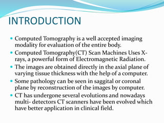
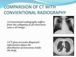
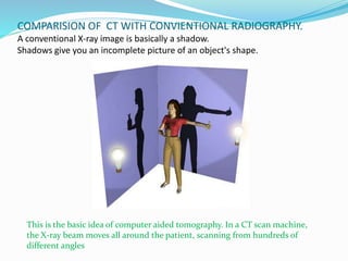
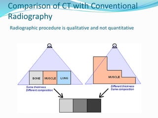
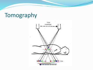
SlideShare a Scribd company logo
Presented by :Rituraj Mishra.
B.Sc.MIT, 2013
Moderator: Mr. Ranjit Kumar Jha
INTRODUCTION
 Computed Tomography is a well accepted imaging
modality for evaluation of the entire body.
 Computed Tomography(CT) Scan Machines Uses X-
rays, a powerful form of Electromagnetic Radiation.
 The images are obtained directly in the axial plane of
varying tissue thickness with the help of a computer.
 Some pathology can be seen in saggital or coronal
plane by reconstruction of the images by computer.
 CT has undergone several evolutions and nowadays
multi- detectors CT scanners have been evolved which
have better application in clinical field.
COMPARISION OF CT WITH
CONVIENTIONAL RADIOGRAPHY
Conventional radiography suffers
from the collapsing of 3D structures
onto a 2D image.
CT gives accurate diagnostic
information about the
distribution of structures inside
the body.
COMPARISION OF CT WITH CONVIENTIONAL RADIOGRAPHY.
A conventional X-ray image is basically a shadow.
Shadows give you an incomplete picture of an object's shape.
This is the basic idea of computer aided tomography. In a CT scan machine,
the X-ray beam moves all around the patient, scanning from hundreds of
different angles
Comparison of CT with Conventional
Radiography
Radiographic procedure is qualitative and not quantitative
ADVANTAGE OF COMPUTED TOMOGRAPHY
OVER CONVIENTIONAL RADIOGRAPHY.
 To overcome superimposition of structures.
 To improve contrast of the image.
 To measure small differences in tissue contrast.
TOMOGRAPHY
 Imaging of Layer/Slice.
Principle
Images of structures lying above and below the plane
are blurred out due to motion unsharpness while the
structures lying in plane of interest appear sharp in in
the image.
Tomography
PRINCIPLE OF COMPUTED
TOMOGRAPHY
 The internal structure of the object can be
reconstructed from multiple projections of the
object.
 Mathematically principle of CT was first developed in
1917 by Radon.
 Proved that image of unknown object could be
produced if one had several number of projections
throughout the object.
VARIOUS PARAMETERS OF CT
 SLICE
 MATRIX
 PIXEL
 VOXEL
 CT NUMBER
 WINDOWING
 WINDOW WIDTH
 WINDOW LEVEL
 PITCH
SLICE/CUT
 The cross section portion of body which is scanned for
production of CT image is called Slice.
 The slice has width and therefore volume.
 The width is determined by width of the x rays beam.
Cross Sectional Slices
Think like looking into the loaf of bread by cutting into
the thin slices and then viewing the slice individually.
MATRIX
 The CT image is represented as the Matrix of the
number.
 A two dimensional array of numbers arranged in rows
and columns is called Matrix.
 Each number represent
the value of the image at
that location.
PIXEL
 Each square in a matrix is called a pixel.
 Also known as picture element.
VOXEL
 Each individual element or number in the image
matrix represents a three dimensional volume element
in object called VOXEL.
CT NUMBER
 The numbers in the image matrix is called CT
NUMBER.
 Each pixel has a number which represents the x-ray
attenuation in the corresponding voxel of the object.
HOUNSFIELD UNITS(HU)
 Related to different composition and nature of Tissue.
 The CT NUMBER is also known as Hounsfield
units(HU).
 Represent the density of tissue.
 Different Tissue have different CT number Range in
HU.
Air - 1000
Fat -100
Pure water 0
CSF 15
White matter 45
Gray matter 40
Blood 20
Bone/calcification +1000
TISSUE AND CT NUMBER APPROXIMATE
WINDOWING is a system where the CT no. range of
interest is spread cover the full grey scale available on
the display system
WINDOW WIDTH –Means total range of CT no.
values selected for gray scale interpretation.
It corresponds to contrast of the image.
WINDOW LEVEL– represents the CT no. selected for
the centre of the range of the no. displayed on the
image. It corresponds to brightness of image .
Pitch
 The relationship between patient and tube motion is
called Pitch.
 It is defined as table movement during each
revolution of x-ray tube divided by collimation
width.
 For example: For a 5mm section, if patient moves
10mm during the time it takes for the x-ray tube to
rotate through 360˚, the pitch is 2.
 Increasing pitch reduces the scan time and patient
dose.
STEPS OF CT IMAGE FORMATION
Phase of CT scanning
1.Scanning the patient or data Acquisition
a)X-ray Generator
b)X-ray Tube
c)X-ray Filtration System
d)Detector System
2.Reconstruction
a)Simple back projection
b)Iterative method
c)Analytical method
3.Display
DATA ACQUISTION
The scanning process begins with data
acquisition
Data Acquisition refers to a method by
which the patient is systematically
scanned by the X ray tube and detectors
to collect enough information for image
reconstruction
Major components of Data Acquisition
System(DAS)
a)X-ray Generators
Generators are located on rotating scan frames within
the CT gantry to accommodate slip Ring.
Power: 50 to 80kw
Frequency: 5 to 50kHz
KVp: 80-120
mA:80-500
b) X-ray Tube
 Rotating anode x-ray tube with unique cooling.
 Small focal spot size (0.6mm) to improve spatial resolution.
 Anode heating capacity:1MHU to 7MHU
 Cooling rate:1MHU per minute.
c)X-ray Beam Filtration System
 CT employs monochromatic beam but radiation from
CT X-ray tube is polychromatic. so, X-ray beam is shaped by
compensation filter.
a)Pre patient Collimators: Reduces the patient dose.
b)Post patient Collimators: Reduces the scattered radiation detectors.
Overall Functions of
Collimators.
 To decrease scatter
radiation
 To reduce patient
dose
 To improve image
quality
 Collimator width
determines the slice
thickness
d)Detectors
The detectors gather information by measuring the x-ray
transmission through the patient.
 Two types:
Scintillation crystal detector
(Cadmium tungstate+ Si Photodiode)
Can be used in third and fourth generation scanners
Xenon gas ionisation chamber
Can be used in third generation scanners only
2)Reconstruction
 Reproduction of an image from raw data is called
Reconstruction.
A)Simple back projection
The image is created by reflecting the attenuation
profiles back in same direction they were obtained.
B)Iterative method
It start with assumption that all point in matrix have
same value and it was compared with measured value
and make correction until Values come with in
acceptable range.
It contain three correction factor
1. SIMULTANEOUS RECONSTRUCTION
2. RAY BY RAY CORRECTION
3. POINT BY POINT CORRECTION
C)Analytical Method
Today commonly used .
Two popular method used in that method are:-
1. 2-D FOURIER ANALYSIS
2.FILTERED BACK PROJECTION
2-D FOURIER ANALYSIS
In it any function of time or space can be represented by the
sum of various frequencies and amplitude of sine and
cosine waves.
For example the actual projected image of original object is
more rounded than those shown which would be slowly
simplify and corrected by Fourier transformation.
2-D FOURIER ANALYSIS
FILTERED BACK PROJECTION
Same as back projection except that the image is filtered,
or Modified to exactly counterbalance the effect of
sudden density Changes , which cause blurring(star
like pattern) in simple back projection.
3)Display
 The reconstructed image is displayed on the monitor.
It is a digital image.
 It consists of 2D representation of 3D object in the
form of pixels.
 CT pixel size is determined by dividing the FOV by
matrix Size which is generally 512*512.
 PIXEL SIZE= FOV (mm)/ MATRIX SIZE
Generations of CT Scan
First Generation
 Narrow pencil beam
 Single detector
 Detector used is made up of NaI.
 Translate –Rotate movements of
Tube- detector combination
 Scan time-5mins.
 Designed only for evaluation
of brain.
First generation CT Scanner
•Head kept enclosed in a water
bath
•Paired detectors
•A reference detector
Second Generation CT Scanner
Second Generation
 Narrow fan beam
 Linear detector array(5 to30)
 Translate-Rotate movements of Tube-Detector
combination
 Fewer linear movements are needed as there are
more detectors to gather the data.
 Between linear movements, the gantry rotated 30o
 Scan time~30secs(advantage over first generation)
Third Generation
•Rotate(tube)Rotate(detectors)
Motion.
•Pulsed wide fan beam.
•Arc of detectors(600-900)
•Detectors are perfectly aligned
with the X-Ray tube
•Both Xenon and scintillation
crystal detectors can be used
•Scan time< 5secs
•Disadvantage: Ring Artifacts
due to electronic drift between
many detectors.
Fourth Generation
Fourth Generation
 Complete circular array of about 1200 to 4800
stationary detectors
 Single x-ray tube rotates with in the circular array
of detectors
 Wide fan beam to cover the entire patient
 Scan time of newer scanners is about ½ s or, <2s.
 Designed to address ring artifacts by keeping
detector assembly stationary.
 Disadvantage: High cost.
Fifth Generation
 stationary/stationary
 Developed specifically for cardiac tomographic imaging
 No conventional x-ray tube; large arc of tungsten encircles
patient and lies directly opposite to the detector ring
 Electron beam steered around the patient to strike the
annular tungsten target
 Capable of 50-msec scan times; can produce fast-frame-
rate CT movies of the beating heart
 Electron gun
 Large Arcs of tungsten
targets
 Detector ring
 17 slices per second
CT SCAN IN OUR RADIOLOGY
DEPARTMENT.(16 SLICES)
Patient Positioning and Data
Acquisition
TECHNICAL SPECIFICATION
(Hitachi ECLOS 16)
 CT scanner mode: Multislice
 Slices per rotation: 16
 Other rotation speed options: 1.0, 1.5, 2.0, 3.0 seconds
 Minimum rotation speed: 0.8 seconds
 Gantry diameter: 70 cm
 Maximum beam width (cm): 2 cm
 Table weight limit: 495 lbs
 Table movement range vertically/longitudinally: 42 to 100 cm
vertical, 186 cm horizontal
 X-ray generator kV range: 100, 120, 130 kVp
 Maximum scan range: 175 cm
 X-ray tube heat capacity: 5.0 MHU
 Power requirements: 3-phase, 200 Amp max.
SPIRAL/HELICAL CT
 Spiral/Helical scanning uses third generation or fourth
generation slip ring design.
 Spiral computed tomography (or helical computed
tomography) is a computed tomography(CT) technology in
which the source and detector travel along a helical path
relative to the object. Typical implementations involve
moving the patient couch through the bore of the scanner
whilst the gantry rotates. Spiral CT can achieve improved
image resolution for a given radiation dose, compared to
individual slice acquisition. Most modern hospitals
currently use spiral CT scanners.
SLIP RING TECHNOLOGY
 In conventional CT scanning there was a paused
between each gantry rotation. But in Helical CT, Slip
Ring technology is used which allows continuous
rotation of gantry without interruption.
 Slip Rings are electrical conducting brushes and
component of gantry transferring the data or,
electrical energy to and from the stationary part of
gantry to rotating part of gantry for continuous
rotation of gantry.
Contd….
 There are usually three slip rings made up of
conduction materials(i.e. Sliver and Graphite.)
 First Slip Ring provides high voltage power to X-ray
tube.
 Second provide low voltage to control system on
rotating gantry and
 Third Slip Ring transfers digital data from rotating
detectors arrays.
MULTISLICE/MULTIDETECTOR CT
 Multidetector computed tomography(MDCT) is a form of
computed tomography (CT) technology for diagnostic
imaging.
 In MDCT, a two-dimensional array of detector elements
replaces the linear array of detector elements used in
typical conventional and helical CT scanners. The two-
dimensional detector array permits CT scanners to acquire
multiple slices or sections simultaneously and greatly
increase the speed of CT image acquisition.
 Image reconstruction in MDCT is more complicated than
that in single section CT.
DUAL SOURCE CT
Dual Source CT (DSCT) is equipped
with two X-ray tubes.
Two corresponding detectors are
oriented in the gantry with an angular
offset of 90 degrees.
ADVANTAGES
1) High temporal resolution(in
response to time domain) for
cardiac imaging without β
blockers which means heart rate
is independent upon temporal
resolution.
2) Less radiation dose even for
obese patient.
3) Faster acquisition time with
shortest breathe hold.
DUAL ENERGY CT
Standard computed tomography (CT)
scanners use normal X-rays to make
cross-sectional ‘slice-like’ pictures or
images of the body.
A dual energy CT scanner is fairly new
technology that uses both the normal
X-ray and also a second less powerful X-
ray to make the images.
Two pictures are taken of the same
slice at different energies.(i.e. 80/140KV
,100/140KV Or,70/150KV)
This gives dual energy CT additional
advantages over standard CT for a wide
range of tests and procedures.
Most commonly used for CT
Angiography.
PORTABLE CT SCAN
PORTABLE CT SCAN
 As the world’s first portable, full-body, 32-slice CT (computed
tomography) scanner, BodyTom is a multi-departmental
imaging solution capable of transforming any room in the
hospital into an advanced imaging suite. The system boasts an
impressive 85cm gantry and 60cm field of view, the largest field
of view available in a portable CT scanner.
 The battery-powered BodyTom with an innovative internal drive
system can easily be transported from room to room and is
compatible with PACS, planning systems, surgical and robotic
navigation systems.
 Uniquely designed to accommodate patients of all sizes,
BodyTom provides point-of-care CT imaging wherever high-
quality CT images are needed, including the operating room,
intensive care unit, radiation oncology suites, and the emergency
department.
RADIATION DOSE IN CT
 Volume Computed Tomography Dose Index (CTDIvol) is a
standardized parameter to measure Scanner Radiation Output
 CTDIvol provides information about the amount of radiation
used to perform the study.
 CTDIvol is NOT patient dose
 CTDIvol is reported in units of mGy for either a 16-cm
(for head exams) or 32-cm (for body exams) diameter.
 AAPM (American Association of Physicts in Medicine)
introduces a parameter known as the Size Specific Dose
Estimate (SSDE) to allow estimation of patient dose based on
CTDIvol and patient size.
 For the same CTDIvol, a smaller patient will tend to have a
higher patient dose than a larger patient.
EFFECTIVE DOSE (mSv)
CT
 HEAD------------ 2
 CHEST ---------- 8
 ABDOMEN --10
 PELVIS -------10
GENERAL RADIOGRAPHY
 SKULL -------- 0.07
 CHEST PA ---- 0.02
 ABDOMEN --- 1
 PELVIS -------- 0.7
computedtomography-170122041110.pdf

More Related Content

What's hot

Radiology day 1 mammography
Radiology day 1 mammographyRadiology day 1 mammography
Radiology day 1 mammography
Vibhay Pareek
 
Mammography Positioning Technique for Additional Views
Mammography Positioning Technique for Additional Views Mammography Positioning Technique for Additional Views
Mammography Positioning Technique for Additional Views
Selin Prasad
 
Mr Mammography New
Mr Mammography NewMr Mammography New
CT RADIATION DOSE REDUCTION
CT RADIATION DOSE REDUCTION CT RADIATION DOSE REDUCTION
CT RADIATION DOSE REDUCTION
Ganesan Yogananthem
 
Breast imaging update
Breast imaging updateBreast imaging update
Breast imaging update
Gregorio Cortes-Maisonet, MD, CHCP
 
Mri physics
Mri physicsMri physics
Mri physics
Archana Koshy
 
RADIOLOGY PRESENTATION
RADIOLOGY PRESENTATIONRADIOLOGY PRESENTATION
RADIOLOGY PRESENTATION
Suneth Weerarathna
 
magnetic resonance in angiography
magnetic resonance in  angiography magnetic resonance in  angiography
magnetic resonance in angiography
BISHAL KHANAL
 
Mri basics
Mri basicsMri basics
Mri basics
Shrikant Nagare
 
MRI BREAST PPT
MRI BREAST PPTMRI BREAST PPT
MRI BREAST PPT
Naba Kumar Barman
 
CT Angiography presentation
CT Angiography presentation CT Angiography presentation
CT Angiography presentation
Shatha M
 
Tissue harmonic imaging
Tissue harmonic imaging Tissue harmonic imaging
Tissue harmonic imaging
MAMTA PANDA
 
Mri physics PART-1
Mri physics PART-1Mri physics PART-1
Mri physics PART-1
Deepak Garg
 
Basic principles of mri
Basic principles of mriBasic principles of mri
Basic principles of mri
ramya prathyusha
 
CT image acquisition
CT image acquisitionCT image acquisition
CT image acquisition
dypradio
 
Image Contrast, Noise, Resolution
Image Contrast, Noise, ResolutionImage Contrast, Noise, Resolution
Image Contrast, Noise, Resolution
Miami Cancer Institute
 
L 4 ct physics
L 4  ct physicsL 4  ct physics
L 4 ct physics
Shahid Younas
 
Elastography
ElastographyElastography
Elastography
Sameer Peer
 
Mri physics
Mri physicsMri physics
Mri physics
cpmrocksatgmc
 
MRI-Magnetic Resonance Elastography (MRE) -Avinesh Shrestha
MRI-Magnetic Resonance Elastography (MRE) -Avinesh ShresthaMRI-Magnetic Resonance Elastography (MRE) -Avinesh Shrestha
MRI-Magnetic Resonance Elastography (MRE) -Avinesh Shrestha
Avinesh Shrestha
 

What's hot (20)

Radiology day 1 mammography
Radiology day 1 mammographyRadiology day 1 mammography
Radiology day 1 mammography
 
Mammography Positioning Technique for Additional Views
Mammography Positioning Technique for Additional Views Mammography Positioning Technique for Additional Views
Mammography Positioning Technique for Additional Views
 
Mr Mammography New
Mr Mammography NewMr Mammography New
Mr Mammography New
 
CT RADIATION DOSE REDUCTION
CT RADIATION DOSE REDUCTION CT RADIATION DOSE REDUCTION
CT RADIATION DOSE REDUCTION
 
Breast imaging update
Breast imaging updateBreast imaging update
Breast imaging update
 
Mri physics
Mri physicsMri physics
Mri physics
 
RADIOLOGY PRESENTATION
RADIOLOGY PRESENTATIONRADIOLOGY PRESENTATION
RADIOLOGY PRESENTATION
 
magnetic resonance in angiography
magnetic resonance in  angiography magnetic resonance in  angiography
magnetic resonance in angiography
 
Mri basics
Mri basicsMri basics
Mri basics
 
MRI BREAST PPT
MRI BREAST PPTMRI BREAST PPT
MRI BREAST PPT
 
CT Angiography presentation
CT Angiography presentation CT Angiography presentation
CT Angiography presentation
 
Tissue harmonic imaging
Tissue harmonic imaging Tissue harmonic imaging
Tissue harmonic imaging
 
Mri physics PART-1
Mri physics PART-1Mri physics PART-1
Mri physics PART-1
 
Basic principles of mri
Basic principles of mriBasic principles of mri
Basic principles of mri
 
CT image acquisition
CT image acquisitionCT image acquisition
CT image acquisition
 
Image Contrast, Noise, Resolution
Image Contrast, Noise, ResolutionImage Contrast, Noise, Resolution
Image Contrast, Noise, Resolution
 
L 4 ct physics
L 4  ct physicsL 4  ct physics
L 4 ct physics
 
Elastography
ElastographyElastography
Elastography
 
Mri physics
Mri physicsMri physics
Mri physics
 
MRI-Magnetic Resonance Elastography (MRE) -Avinesh Shrestha
MRI-Magnetic Resonance Elastography (MRE) -Avinesh ShresthaMRI-Magnetic Resonance Elastography (MRE) -Avinesh Shrestha
MRI-Magnetic Resonance Elastography (MRE) -Avinesh Shrestha
 

Similar to computedtomography-170122041110.pdf

Computed Tomography and Spiral Computed Tomography
Computed Tomography and Spiral Computed Tomography Computed Tomography and Spiral Computed Tomography
Computed Tomography and Spiral Computed Tomography
JAMES JACKY
 
Computed tomography
Computed tomographyComputed tomography
Computed tomography
Rituraj Mishra
 
Basic principle of CT and generation of CT.pptx
Basic principle of CT and generation of CT.pptxBasic principle of CT and generation of CT.pptx
Basic principle of CT and generation of CT.pptx
sarita gaire
 
Ct Basics
Ct BasicsCt Basics
Ct Basics
Pramod Krishnan
 
Physics of Multidetector CT Scan
Physics of Multidetector CT ScanPhysics of Multidetector CT Scan
Physics of Multidetector CT Scan
Dr Varun Bansal
 
CT ITS BASIC PHYSICS
CT ITS BASIC PHYSICSCT ITS BASIC PHYSICS
CT ITS BASIC PHYSICS
DEEPAK
 
Computed Tomography
Computed TomographyComputed Tomography
Computed Tomography
Sujan Poudel
 
computed Tomography
computed Tomographycomputed Tomography
medical equipment lec 6 CT scan
medical equipment lec 6 CT scanmedical equipment lec 6 CT scan
medical equipment lec 6 CT scan
cairo university
 
CT scanner
CT scannerCT scanner
CT scanner
Sabari Kumar
 
CT Image reconstruction
CT Image reconstructionCT Image reconstruction
CT Image reconstruction
Santosh Ojha
 
Basic Principles and Concepts of Computed Tomography (CT)
Basic Principles and Concepts of Computed Tomography (CT)Basic Principles and Concepts of Computed Tomography (CT)
Basic Principles and Concepts of Computed Tomography (CT)
AayushiPaul1
 
Sandhya Dhyani (48437) CT SCAN AND MRI.pptx
Sandhya Dhyani (48437) CT SCAN AND MRI.pptxSandhya Dhyani (48437) CT SCAN AND MRI.pptx
Sandhya Dhyani (48437) CT SCAN AND MRI.pptx
GBPUAT Pantnagar
 
X ray tomography
X ray tomographyX ray tomography
LCU RDG 402 PRINCIPLES OF COMPUTED TOMOGRAPHY.pptx
LCU RDG 402  PRINCIPLES OF COMPUTED TOMOGRAPHY.pptxLCU RDG 402  PRINCIPLES OF COMPUTED TOMOGRAPHY.pptx
LCU RDG 402 PRINCIPLES OF COMPUTED TOMOGRAPHY.pptx
EmmanuelOluseyi1
 
Physics of ct mri
Physics of ct mriPhysics of ct mri
Physics of ct mri
Lokender Yadav
 
4.pptx
4.pptx4.pptx
Basics of CT & MRI
Basics of CT & MRIBasics of CT & MRI
Basics of CT & MRI
Vibhuti Kaul
 
Comparison of ct and cbct
Comparison of ct and cbct Comparison of ct and cbct
Comparison of ct and cbct
Amritha James
 
Ct scan by sajid ejaz
Ct scan by sajid ejazCt scan by sajid ejaz
Ct scan by sajid ejaz
SAJIDEJAZ1
 

Similar to computedtomography-170122041110.pdf (20)

Computed Tomography and Spiral Computed Tomography
Computed Tomography and Spiral Computed Tomography Computed Tomography and Spiral Computed Tomography
Computed Tomography and Spiral Computed Tomography
 
Computed tomography
Computed tomographyComputed tomography
Computed tomography
 
Basic principle of CT and generation of CT.pptx
Basic principle of CT and generation of CT.pptxBasic principle of CT and generation of CT.pptx
Basic principle of CT and generation of CT.pptx
 
Ct Basics
Ct BasicsCt Basics
Ct Basics
 
Physics of Multidetector CT Scan
Physics of Multidetector CT ScanPhysics of Multidetector CT Scan
Physics of Multidetector CT Scan
 
CT ITS BASIC PHYSICS
CT ITS BASIC PHYSICSCT ITS BASIC PHYSICS
CT ITS BASIC PHYSICS
 
Computed Tomography
Computed TomographyComputed Tomography
Computed Tomography
 
computed Tomography
computed Tomographycomputed Tomography
computed Tomography
 
medical equipment lec 6 CT scan
medical equipment lec 6 CT scanmedical equipment lec 6 CT scan
medical equipment lec 6 CT scan
 
CT scanner
CT scannerCT scanner
CT scanner
 
CT Image reconstruction
CT Image reconstructionCT Image reconstruction
CT Image reconstruction
 
Basic Principles and Concepts of Computed Tomography (CT)
Basic Principles and Concepts of Computed Tomography (CT)Basic Principles and Concepts of Computed Tomography (CT)
Basic Principles and Concepts of Computed Tomography (CT)
 
Sandhya Dhyani (48437) CT SCAN AND MRI.pptx
Sandhya Dhyani (48437) CT SCAN AND MRI.pptxSandhya Dhyani (48437) CT SCAN AND MRI.pptx
Sandhya Dhyani (48437) CT SCAN AND MRI.pptx
 
X ray tomography
X ray tomographyX ray tomography
X ray tomography
 
LCU RDG 402 PRINCIPLES OF COMPUTED TOMOGRAPHY.pptx
LCU RDG 402  PRINCIPLES OF COMPUTED TOMOGRAPHY.pptxLCU RDG 402  PRINCIPLES OF COMPUTED TOMOGRAPHY.pptx
LCU RDG 402 PRINCIPLES OF COMPUTED TOMOGRAPHY.pptx
 
Physics of ct mri
Physics of ct mriPhysics of ct mri
Physics of ct mri
 
4.pptx
4.pptx4.pptx
4.pptx
 
Basics of CT & MRI
Basics of CT & MRIBasics of CT & MRI
Basics of CT & MRI
 
Comparison of ct and cbct
Comparison of ct and cbct Comparison of ct and cbct
Comparison of ct and cbct
 
Ct scan by sajid ejaz
Ct scan by sajid ejazCt scan by sajid ejaz
Ct scan by sajid ejaz
 

More from VanshikaGarg76

CT COMPONENTS
CT COMPONENTSCT COMPONENTS
CT COMPONENTS
VanshikaGarg76
 
upper limb
upper limbupper limb
upper limb
VanshikaGarg76
 
Imaging During Pregnancy
Imaging During Pregnancy Imaging During Pregnancy
Imaging During Pregnancy
VanshikaGarg76
 
macronutrients and micronutrients
macronutrients and micronutrientsmacronutrients and micronutrients
macronutrients and micronutrients
VanshikaGarg76
 
rdg4011stsem-dentalradiography-180219135013.pdf
rdg4011stsem-dentalradiography-180219135013.pdfrdg4011stsem-dentalradiography-180219135013.pdf
rdg4011stsem-dentalradiography-180219135013.pdf
VanshikaGarg76
 
OPERATION THEATRE RADIOGRAPHY (3)-1.pptx
OPERATION THEATRE RADIOGRAPHY (3)-1.pptxOPERATION THEATRE RADIOGRAPHY (3)-1.pptx
OPERATION THEATRE RADIOGRAPHY (3)-1.pptx
VanshikaGarg76
 
pleuraleffusion-160424141916 (1) (2)-1.pdf
pleuraleffusion-160424141916 (1) (2)-1.pdfpleuraleffusion-160424141916 (1) (2)-1.pdf
pleuraleffusion-160424141916 (1) (2)-1.pdf
VanshikaGarg76
 
abdomenradiography-121101102111-phpapp02 (1).pdf
abdomenradiography-121101102111-phpapp02 (1).pdfabdomenradiography-121101102111-phpapp02 (1).pdf
abdomenradiography-121101102111-phpapp02 (1).pdf
VanshikaGarg76
 
pres-131112084302-phpapp01.pdf
pres-131112084302-phpapp01.pdfpres-131112084302-phpapp01.pdf
pres-131112084302-phpapp01.pdf
VanshikaGarg76
 
radiationunits-140511045254-phpapp02.pdf
radiationunits-140511045254-phpapp02.pdfradiationunits-140511045254-phpapp02.pdf
radiationunits-140511045254-phpapp02.pdf
VanshikaGarg76
 
Unit IV - Radio activity-1.pptx
Unit IV - Radio activity-1.pptxUnit IV - Radio activity-1.pptx
Unit IV - Radio activity-1.pptx
VanshikaGarg76
 
mri safety the dos and do nots-1.pptx
mri safety the dos and do nots-1.pptxmri safety the dos and do nots-1.pptx
mri safety the dos and do nots-1.pptx
VanshikaGarg76
 
socialissuesandenvironment-161129185634 (1).pdf
socialissuesandenvironment-161129185634 (1).pdfsocialissuesandenvironment-161129185634 (1).pdf
socialissuesandenvironment-161129185634 (1).pdf
VanshikaGarg76
 
Magnetic_Resonance_(MR)_spectroscopy-1.pptx
Magnetic_Resonance_(MR)_spectroscopy-1.pptxMagnetic_Resonance_(MR)_spectroscopy-1.pptx
Magnetic_Resonance_(MR)_spectroscopy-1.pptx
VanshikaGarg76
 
ultrasonography.pptx
ultrasonography.pptxultrasonography.pptx
ultrasonography.pptx
VanshikaGarg76
 
mammography
mammography mammography
mammography
VanshikaGarg76
 
PET CT-1.pptx
PET CT-1.pptxPET CT-1.pptx
PET CT-1.pptx
VanshikaGarg76
 
mr angiography.pptx
mr angiography.pptxmr angiography.pptx
mr angiography.pptx
VanshikaGarg76
 
GRIDS_TYPES.pptx
GRIDS_TYPES.pptxGRIDS_TYPES.pptx
GRIDS_TYPES.pptx
VanshikaGarg76
 
BASIC PRINCIPLE OF MRI.pptx
BASIC PRINCIPLE OF MRI.pptxBASIC PRINCIPLE OF MRI.pptx
BASIC PRINCIPLE OF MRI.pptx
VanshikaGarg76
 

More from VanshikaGarg76 (20)

CT COMPONENTS
CT COMPONENTSCT COMPONENTS
CT COMPONENTS
 
upper limb
upper limbupper limb
upper limb
 
Imaging During Pregnancy
Imaging During Pregnancy Imaging During Pregnancy
Imaging During Pregnancy
 
macronutrients and micronutrients
macronutrients and micronutrientsmacronutrients and micronutrients
macronutrients and micronutrients
 
rdg4011stsem-dentalradiography-180219135013.pdf
rdg4011stsem-dentalradiography-180219135013.pdfrdg4011stsem-dentalradiography-180219135013.pdf
rdg4011stsem-dentalradiography-180219135013.pdf
 
OPERATION THEATRE RADIOGRAPHY (3)-1.pptx
OPERATION THEATRE RADIOGRAPHY (3)-1.pptxOPERATION THEATRE RADIOGRAPHY (3)-1.pptx
OPERATION THEATRE RADIOGRAPHY (3)-1.pptx
 
pleuraleffusion-160424141916 (1) (2)-1.pdf
pleuraleffusion-160424141916 (1) (2)-1.pdfpleuraleffusion-160424141916 (1) (2)-1.pdf
pleuraleffusion-160424141916 (1) (2)-1.pdf
 
abdomenradiography-121101102111-phpapp02 (1).pdf
abdomenradiography-121101102111-phpapp02 (1).pdfabdomenradiography-121101102111-phpapp02 (1).pdf
abdomenradiography-121101102111-phpapp02 (1).pdf
 
pres-131112084302-phpapp01.pdf
pres-131112084302-phpapp01.pdfpres-131112084302-phpapp01.pdf
pres-131112084302-phpapp01.pdf
 
radiationunits-140511045254-phpapp02.pdf
radiationunits-140511045254-phpapp02.pdfradiationunits-140511045254-phpapp02.pdf
radiationunits-140511045254-phpapp02.pdf
 
Unit IV - Radio activity-1.pptx
Unit IV - Radio activity-1.pptxUnit IV - Radio activity-1.pptx
Unit IV - Radio activity-1.pptx
 
mri safety the dos and do nots-1.pptx
mri safety the dos and do nots-1.pptxmri safety the dos and do nots-1.pptx
mri safety the dos and do nots-1.pptx
 
socialissuesandenvironment-161129185634 (1).pdf
socialissuesandenvironment-161129185634 (1).pdfsocialissuesandenvironment-161129185634 (1).pdf
socialissuesandenvironment-161129185634 (1).pdf
 
Magnetic_Resonance_(MR)_spectroscopy-1.pptx
Magnetic_Resonance_(MR)_spectroscopy-1.pptxMagnetic_Resonance_(MR)_spectroscopy-1.pptx
Magnetic_Resonance_(MR)_spectroscopy-1.pptx
 
ultrasonography.pptx
ultrasonography.pptxultrasonography.pptx
ultrasonography.pptx
 
mammography
mammography mammography
mammography
 
PET CT-1.pptx
PET CT-1.pptxPET CT-1.pptx
PET CT-1.pptx
 
mr angiography.pptx
mr angiography.pptxmr angiography.pptx
mr angiography.pptx
 
GRIDS_TYPES.pptx
GRIDS_TYPES.pptxGRIDS_TYPES.pptx
GRIDS_TYPES.pptx
 
BASIC PRINCIPLE OF MRI.pptx
BASIC PRINCIPLE OF MRI.pptxBASIC PRINCIPLE OF MRI.pptx
BASIC PRINCIPLE OF MRI.pptx
 

Recently uploaded

Introduction to CHERI technology - Cybersecurity
Introduction to CHERI technology - CybersecurityIntroduction to CHERI technology - Cybersecurity
Introduction to CHERI technology - Cybersecurity
mikeeftimakis1
 
Alt. GDG Cloud Southlake #33: Boule & Rebala: Effective AppSec in SDLC using ...
Alt. GDG Cloud Southlake #33: Boule & Rebala: Effective AppSec in SDLC using ...Alt. GDG Cloud Southlake #33: Boule & Rebala: Effective AppSec in SDLC using ...
Alt. GDG Cloud Southlake #33: Boule & Rebala: Effective AppSec in SDLC using ...
James Anderson
 
Goodbye Windows 11: Make Way for Nitrux Linux 3.5.0!
Goodbye Windows 11: Make Way for Nitrux Linux 3.5.0!Goodbye Windows 11: Make Way for Nitrux Linux 3.5.0!
Goodbye Windows 11: Make Way for Nitrux Linux 3.5.0!
SOFTTECHHUB
 
Let's Integrate MuleSoft RPA, COMPOSER, APM with AWS IDP along with Slack
Let's Integrate MuleSoft RPA, COMPOSER, APM with AWS IDP along with SlackLet's Integrate MuleSoft RPA, COMPOSER, APM with AWS IDP along with Slack
Let's Integrate MuleSoft RPA, COMPOSER, APM with AWS IDP along with Slack
shyamraj55
 
Large Language Model (LLM) and it’s Geospatial Applications
Large Language Model (LLM) and it’s Geospatial ApplicationsLarge Language Model (LLM) and it’s Geospatial Applications
Large Language Model (LLM) and it’s Geospatial Applications
Rohit Gautam
 
UiPath Test Automation using UiPath Test Suite series, part 5
UiPath Test Automation using UiPath Test Suite series, part 5UiPath Test Automation using UiPath Test Suite series, part 5
UiPath Test Automation using UiPath Test Suite series, part 5
DianaGray10
 
GraphSummit Singapore | Neo4j Product Vision & Roadmap - Q2 2024
GraphSummit Singapore | Neo4j Product Vision & Roadmap - Q2 2024GraphSummit Singapore | Neo4j Product Vision & Roadmap - Q2 2024
GraphSummit Singapore | Neo4j Product Vision & Roadmap - Q2 2024
Neo4j
 
Presentation of the OECD Artificial Intelligence Review of Germany
Presentation of the OECD Artificial Intelligence Review of GermanyPresentation of the OECD Artificial Intelligence Review of Germany
Presentation of the OECD Artificial Intelligence Review of Germany
innovationoecd
 
Pushing the limits of ePRTC: 100ns holdover for 100 days
Pushing the limits of ePRTC: 100ns holdover for 100 daysPushing the limits of ePRTC: 100ns holdover for 100 days
Pushing the limits of ePRTC: 100ns holdover for 100 days
Adtran
 
Unlock the Future of Search with MongoDB Atlas_ Vector Search Unleashed.pdf
Unlock the Future of Search with MongoDB Atlas_ Vector Search Unleashed.pdfUnlock the Future of Search with MongoDB Atlas_ Vector Search Unleashed.pdf
Unlock the Future of Search with MongoDB Atlas_ Vector Search Unleashed.pdf
Malak Abu Hammad
 
Climate Impact of Software Testing at Nordic Testing Days
Climate Impact of Software Testing at Nordic Testing DaysClimate Impact of Software Testing at Nordic Testing Days
Climate Impact of Software Testing at Nordic Testing Days
Kari Kakkonen
 
How to Get CNIC Information System with Paksim Ga.pptx
How to Get CNIC Information System with Paksim Ga.pptxHow to Get CNIC Information System with Paksim Ga.pptx
How to Get CNIC Information System with Paksim Ga.pptx
danishmna97
 
PCI PIN Basics Webinar from the Controlcase Team
PCI PIN Basics Webinar from the Controlcase TeamPCI PIN Basics Webinar from the Controlcase Team
PCI PIN Basics Webinar from the Controlcase Team
ControlCase
 
20240607 QFM018 Elixir Reading List May 2024
20240607 QFM018 Elixir Reading List May 202420240607 QFM018 Elixir Reading List May 2024
20240607 QFM018 Elixir Reading List May 2024
Matthew Sinclair
 
みなさんこんにちはこれ何文字まで入るの?40文字以下不可とか本当に意味わからないけどこれ限界文字数書いてないからマジでやばい文字数いけるんじゃないの?えこ...
みなさんこんにちはこれ何文字まで入るの?40文字以下不可とか本当に意味わからないけどこれ限界文字数書いてないからマジでやばい文字数いけるんじゃないの?えこ...みなさんこんにちはこれ何文字まで入るの?40文字以下不可とか本当に意味わからないけどこれ限界文字数書いてないからマジでやばい文字数いけるんじゃないの?えこ...
みなさんこんにちはこれ何文字まで入るの?40文字以下不可とか本当に意味わからないけどこれ限界文字数書いてないからマジでやばい文字数いけるんじゃないの?えこ...
名前 です男
 
How to use Firebase Data Connect For Flutter
How to use Firebase Data Connect For FlutterHow to use Firebase Data Connect For Flutter
How to use Firebase Data Connect For Flutter
Daiki Mogmet Ito
 
Why You Should Replace Windows 11 with Nitrux Linux 3.5.0 for enhanced perfor...
Why You Should Replace Windows 11 with Nitrux Linux 3.5.0 for enhanced perfor...Why You Should Replace Windows 11 with Nitrux Linux 3.5.0 for enhanced perfor...
Why You Should Replace Windows 11 with Nitrux Linux 3.5.0 for enhanced perfor...
SOFTTECHHUB
 
20240609 QFM020 Irresponsible AI Reading List May 2024
20240609 QFM020 Irresponsible AI Reading List May 202420240609 QFM020 Irresponsible AI Reading List May 2024
20240609 QFM020 Irresponsible AI Reading List May 2024
Matthew Sinclair
 
Encryption in Microsoft 365 - ExpertsLive Netherlands 2024
Encryption in Microsoft 365 - ExpertsLive Netherlands 2024Encryption in Microsoft 365 - ExpertsLive Netherlands 2024
Encryption in Microsoft 365 - ExpertsLive Netherlands 2024
Albert Hoitingh
 
Monitoring Java Application Security with JDK Tools and JFR Events
Monitoring Java Application Security with JDK Tools and JFR EventsMonitoring Java Application Security with JDK Tools and JFR Events
Monitoring Java Application Security with JDK Tools and JFR Events
Ana-Maria Mihalceanu
 

Recently uploaded (20)

Introduction to CHERI technology - Cybersecurity
Introduction to CHERI technology - CybersecurityIntroduction to CHERI technology - Cybersecurity
Introduction to CHERI technology - Cybersecurity
 
Alt. GDG Cloud Southlake #33: Boule & Rebala: Effective AppSec in SDLC using ...
Alt. GDG Cloud Southlake #33: Boule & Rebala: Effective AppSec in SDLC using ...Alt. GDG Cloud Southlake #33: Boule & Rebala: Effective AppSec in SDLC using ...
Alt. GDG Cloud Southlake #33: Boule & Rebala: Effective AppSec in SDLC using ...
 
Goodbye Windows 11: Make Way for Nitrux Linux 3.5.0!
Goodbye Windows 11: Make Way for Nitrux Linux 3.5.0!Goodbye Windows 11: Make Way for Nitrux Linux 3.5.0!
Goodbye Windows 11: Make Way for Nitrux Linux 3.5.0!
 
Let's Integrate MuleSoft RPA, COMPOSER, APM with AWS IDP along with Slack
Let's Integrate MuleSoft RPA, COMPOSER, APM with AWS IDP along with SlackLet's Integrate MuleSoft RPA, COMPOSER, APM with AWS IDP along with Slack
Let's Integrate MuleSoft RPA, COMPOSER, APM with AWS IDP along with Slack
 
Large Language Model (LLM) and it’s Geospatial Applications
Large Language Model (LLM) and it’s Geospatial ApplicationsLarge Language Model (LLM) and it’s Geospatial Applications
Large Language Model (LLM) and it’s Geospatial Applications
 
UiPath Test Automation using UiPath Test Suite series, part 5
UiPath Test Automation using UiPath Test Suite series, part 5UiPath Test Automation using UiPath Test Suite series, part 5
UiPath Test Automation using UiPath Test Suite series, part 5
 
GraphSummit Singapore | Neo4j Product Vision & Roadmap - Q2 2024
GraphSummit Singapore | Neo4j Product Vision & Roadmap - Q2 2024GraphSummit Singapore | Neo4j Product Vision & Roadmap - Q2 2024
GraphSummit Singapore | Neo4j Product Vision & Roadmap - Q2 2024
 
Presentation of the OECD Artificial Intelligence Review of Germany
Presentation of the OECD Artificial Intelligence Review of GermanyPresentation of the OECD Artificial Intelligence Review of Germany
Presentation of the OECD Artificial Intelligence Review of Germany
 
Pushing the limits of ePRTC: 100ns holdover for 100 days
Pushing the limits of ePRTC: 100ns holdover for 100 daysPushing the limits of ePRTC: 100ns holdover for 100 days
Pushing the limits of ePRTC: 100ns holdover for 100 days
 
Unlock the Future of Search with MongoDB Atlas_ Vector Search Unleashed.pdf
Unlock the Future of Search with MongoDB Atlas_ Vector Search Unleashed.pdfUnlock the Future of Search with MongoDB Atlas_ Vector Search Unleashed.pdf
Unlock the Future of Search with MongoDB Atlas_ Vector Search Unleashed.pdf
 
Climate Impact of Software Testing at Nordic Testing Days
Climate Impact of Software Testing at Nordic Testing DaysClimate Impact of Software Testing at Nordic Testing Days
Climate Impact of Software Testing at Nordic Testing Days
 
How to Get CNIC Information System with Paksim Ga.pptx
How to Get CNIC Information System with Paksim Ga.pptxHow to Get CNIC Information System with Paksim Ga.pptx
How to Get CNIC Information System with Paksim Ga.pptx
 
PCI PIN Basics Webinar from the Controlcase Team
PCI PIN Basics Webinar from the Controlcase TeamPCI PIN Basics Webinar from the Controlcase Team
PCI PIN Basics Webinar from the Controlcase Team
 
20240607 QFM018 Elixir Reading List May 2024
20240607 QFM018 Elixir Reading List May 202420240607 QFM018 Elixir Reading List May 2024
20240607 QFM018 Elixir Reading List May 2024
 
みなさんこんにちはこれ何文字まで入るの?40文字以下不可とか本当に意味わからないけどこれ限界文字数書いてないからマジでやばい文字数いけるんじゃないの?えこ...
みなさんこんにちはこれ何文字まで入るの?40文字以下不可とか本当に意味わからないけどこれ限界文字数書いてないからマジでやばい文字数いけるんじゃないの?えこ...みなさんこんにちはこれ何文字まで入るの?40文字以下不可とか本当に意味わからないけどこれ限界文字数書いてないからマジでやばい文字数いけるんじゃないの?えこ...
みなさんこんにちはこれ何文字まで入るの?40文字以下不可とか本当に意味わからないけどこれ限界文字数書いてないからマジでやばい文字数いけるんじゃないの?えこ...
 
How to use Firebase Data Connect For Flutter
How to use Firebase Data Connect For FlutterHow to use Firebase Data Connect For Flutter
How to use Firebase Data Connect For Flutter
 
Why You Should Replace Windows 11 with Nitrux Linux 3.5.0 for enhanced perfor...
Why You Should Replace Windows 11 with Nitrux Linux 3.5.0 for enhanced perfor...Why You Should Replace Windows 11 with Nitrux Linux 3.5.0 for enhanced perfor...
Why You Should Replace Windows 11 with Nitrux Linux 3.5.0 for enhanced perfor...
 
20240609 QFM020 Irresponsible AI Reading List May 2024
20240609 QFM020 Irresponsible AI Reading List May 202420240609 QFM020 Irresponsible AI Reading List May 2024
20240609 QFM020 Irresponsible AI Reading List May 2024
 
Encryption in Microsoft 365 - ExpertsLive Netherlands 2024
Encryption in Microsoft 365 - ExpertsLive Netherlands 2024Encryption in Microsoft 365 - ExpertsLive Netherlands 2024
Encryption in Microsoft 365 - ExpertsLive Netherlands 2024
 
Monitoring Java Application Security with JDK Tools and JFR Events
Monitoring Java Application Security with JDK Tools and JFR EventsMonitoring Java Application Security with JDK Tools and JFR Events
Monitoring Java Application Security with JDK Tools and JFR Events
 

computedtomography-170122041110.pdf

  • 1. Presented by :Rituraj Mishra. B.Sc.MIT, 2013 Moderator: Mr. Ranjit Kumar Jha
  • 2. INTRODUCTION  Computed Tomography is a well accepted imaging modality for evaluation of the entire body.  Computed Tomography(CT) Scan Machines Uses X- rays, a powerful form of Electromagnetic Radiation.  The images are obtained directly in the axial plane of varying tissue thickness with the help of a computer.  Some pathology can be seen in saggital or coronal plane by reconstruction of the images by computer.  CT has undergone several evolutions and nowadays multi- detectors CT scanners have been evolved which have better application in clinical field.
  • 3. COMPARISION OF CT WITH CONVIENTIONAL RADIOGRAPHY Conventional radiography suffers from the collapsing of 3D structures onto a 2D image. CT gives accurate diagnostic information about the distribution of structures inside the body.
  • 4. COMPARISION OF CT WITH CONVIENTIONAL RADIOGRAPHY. A conventional X-ray image is basically a shadow. Shadows give you an incomplete picture of an object's shape. This is the basic idea of computer aided tomography. In a CT scan machine, the X-ray beam moves all around the patient, scanning from hundreds of different angles
  • 5. Comparison of CT with Conventional Radiography Radiographic procedure is qualitative and not quantitative
  • 6. ADVANTAGE OF COMPUTED TOMOGRAPHY OVER CONVIENTIONAL RADIOGRAPHY.  To overcome superimposition of structures.  To improve contrast of the image.  To measure small differences in tissue contrast.
  • 7. TOMOGRAPHY  Imaging of Layer/Slice. Principle Images of structures lying above and below the plane are blurred out due to motion unsharpness while the structures lying in plane of interest appear sharp in in the image.
  • 9. PRINCIPLE OF COMPUTED TOMOGRAPHY  The internal structure of the object can be reconstructed from multiple projections of the object.  Mathematically principle of CT was first developed in 1917 by Radon.  Proved that image of unknown object could be produced if one had several number of projections throughout the object.
  • 10. VARIOUS PARAMETERS OF CT  SLICE  MATRIX  PIXEL  VOXEL  CT NUMBER  WINDOWING  WINDOW WIDTH  WINDOW LEVEL  PITCH
  • 11. SLICE/CUT  The cross section portion of body which is scanned for production of CT image is called Slice.  The slice has width and therefore volume.  The width is determined by width of the x rays beam.
  • 12. Cross Sectional Slices Think like looking into the loaf of bread by cutting into the thin slices and then viewing the slice individually.
  • 13. MATRIX  The CT image is represented as the Matrix of the number.  A two dimensional array of numbers arranged in rows and columns is called Matrix.  Each number represent the value of the image at that location.
  • 14. PIXEL  Each square in a matrix is called a pixel.  Also known as picture element.
  • 15. VOXEL  Each individual element or number in the image matrix represents a three dimensional volume element in object called VOXEL.
  • 16. CT NUMBER  The numbers in the image matrix is called CT NUMBER.  Each pixel has a number which represents the x-ray attenuation in the corresponding voxel of the object.
  • 17. HOUNSFIELD UNITS(HU)  Related to different composition and nature of Tissue.  The CT NUMBER is also known as Hounsfield units(HU).  Represent the density of tissue.  Different Tissue have different CT number Range in HU.
  • 18. Air - 1000 Fat -100 Pure water 0 CSF 15 White matter 45 Gray matter 40 Blood 20 Bone/calcification +1000 TISSUE AND CT NUMBER APPROXIMATE
  • 19. WINDOWING is a system where the CT no. range of interest is spread cover the full grey scale available on the display system WINDOW WIDTH –Means total range of CT no. values selected for gray scale interpretation. It corresponds to contrast of the image. WINDOW LEVEL– represents the CT no. selected for the centre of the range of the no. displayed on the image. It corresponds to brightness of image .
  • 20. Pitch  The relationship between patient and tube motion is called Pitch.  It is defined as table movement during each revolution of x-ray tube divided by collimation width.  For example: For a 5mm section, if patient moves 10mm during the time it takes for the x-ray tube to rotate through 360˚, the pitch is 2.  Increasing pitch reduces the scan time and patient dose.
  • 21. STEPS OF CT IMAGE FORMATION
  • 22. Phase of CT scanning 1.Scanning the patient or data Acquisition a)X-ray Generator b)X-ray Tube c)X-ray Filtration System d)Detector System 2.Reconstruction a)Simple back projection b)Iterative method c)Analytical method 3.Display
  • 23. DATA ACQUISTION The scanning process begins with data acquisition Data Acquisition refers to a method by which the patient is systematically scanned by the X ray tube and detectors to collect enough information for image reconstruction
  • 24. Major components of Data Acquisition System(DAS) a)X-ray Generators Generators are located on rotating scan frames within the CT gantry to accommodate slip Ring. Power: 50 to 80kw Frequency: 5 to 50kHz KVp: 80-120 mA:80-500
  • 25. b) X-ray Tube  Rotating anode x-ray tube with unique cooling.  Small focal spot size (0.6mm) to improve spatial resolution.  Anode heating capacity:1MHU to 7MHU  Cooling rate:1MHU per minute. c)X-ray Beam Filtration System  CT employs monochromatic beam but radiation from CT X-ray tube is polychromatic. so, X-ray beam is shaped by compensation filter. a)Pre patient Collimators: Reduces the patient dose. b)Post patient Collimators: Reduces the scattered radiation detectors.
  • 26. Overall Functions of Collimators.  To decrease scatter radiation  To reduce patient dose  To improve image quality  Collimator width determines the slice thickness
  • 27. d)Detectors The detectors gather information by measuring the x-ray transmission through the patient.  Two types: Scintillation crystal detector (Cadmium tungstate+ Si Photodiode) Can be used in third and fourth generation scanners Xenon gas ionisation chamber Can be used in third generation scanners only
  • 28. 2)Reconstruction  Reproduction of an image from raw data is called Reconstruction. A)Simple back projection The image is created by reflecting the attenuation profiles back in same direction they were obtained.
  • 29. B)Iterative method It start with assumption that all point in matrix have same value and it was compared with measured value and make correction until Values come with in acceptable range. It contain three correction factor 1. SIMULTANEOUS RECONSTRUCTION 2. RAY BY RAY CORRECTION 3. POINT BY POINT CORRECTION
  • 30. C)Analytical Method Today commonly used . Two popular method used in that method are:- 1. 2-D FOURIER ANALYSIS 2.FILTERED BACK PROJECTION
  • 31. 2-D FOURIER ANALYSIS In it any function of time or space can be represented by the sum of various frequencies and amplitude of sine and cosine waves. For example the actual projected image of original object is more rounded than those shown which would be slowly simplify and corrected by Fourier transformation.
  • 33. FILTERED BACK PROJECTION Same as back projection except that the image is filtered, or Modified to exactly counterbalance the effect of sudden density Changes , which cause blurring(star like pattern) in simple back projection.
  • 34.
  • 35. 3)Display  The reconstructed image is displayed on the monitor. It is a digital image.  It consists of 2D representation of 3D object in the form of pixels.  CT pixel size is determined by dividing the FOV by matrix Size which is generally 512*512.  PIXEL SIZE= FOV (mm)/ MATRIX SIZE
  • 36. Generations of CT Scan First Generation  Narrow pencil beam  Single detector  Detector used is made up of NaI.  Translate –Rotate movements of Tube- detector combination  Scan time-5mins.  Designed only for evaluation of brain.
  • 37. First generation CT Scanner •Head kept enclosed in a water bath •Paired detectors •A reference detector
  • 39. Second Generation  Narrow fan beam  Linear detector array(5 to30)  Translate-Rotate movements of Tube-Detector combination  Fewer linear movements are needed as there are more detectors to gather the data.  Between linear movements, the gantry rotated 30o  Scan time~30secs(advantage over first generation)
  • 40. Third Generation •Rotate(tube)Rotate(detectors) Motion. •Pulsed wide fan beam. •Arc of detectors(600-900) •Detectors are perfectly aligned with the X-Ray tube •Both Xenon and scintillation crystal detectors can be used •Scan time< 5secs •Disadvantage: Ring Artifacts due to electronic drift between many detectors.
  • 42. Fourth Generation  Complete circular array of about 1200 to 4800 stationary detectors  Single x-ray tube rotates with in the circular array of detectors  Wide fan beam to cover the entire patient  Scan time of newer scanners is about ½ s or, <2s.  Designed to address ring artifacts by keeping detector assembly stationary.  Disadvantage: High cost.
  • 43. Fifth Generation  stationary/stationary  Developed specifically for cardiac tomographic imaging  No conventional x-ray tube; large arc of tungsten encircles patient and lies directly opposite to the detector ring  Electron beam steered around the patient to strike the annular tungsten target  Capable of 50-msec scan times; can produce fast-frame- rate CT movies of the beating heart
  • 44.  Electron gun  Large Arcs of tungsten targets  Detector ring  17 slices per second
  • 45. CT SCAN IN OUR RADIOLOGY DEPARTMENT.(16 SLICES)
  • 46. Patient Positioning and Data Acquisition
  • 47. TECHNICAL SPECIFICATION (Hitachi ECLOS 16)  CT scanner mode: Multislice  Slices per rotation: 16  Other rotation speed options: 1.0, 1.5, 2.0, 3.0 seconds  Minimum rotation speed: 0.8 seconds  Gantry diameter: 70 cm  Maximum beam width (cm): 2 cm  Table weight limit: 495 lbs  Table movement range vertically/longitudinally: 42 to 100 cm vertical, 186 cm horizontal  X-ray generator kV range: 100, 120, 130 kVp  Maximum scan range: 175 cm  X-ray tube heat capacity: 5.0 MHU  Power requirements: 3-phase, 200 Amp max.
  • 48.
  • 49. SPIRAL/HELICAL CT  Spiral/Helical scanning uses third generation or fourth generation slip ring design.  Spiral computed tomography (or helical computed tomography) is a computed tomography(CT) technology in which the source and detector travel along a helical path relative to the object. Typical implementations involve moving the patient couch through the bore of the scanner whilst the gantry rotates. Spiral CT can achieve improved image resolution for a given radiation dose, compared to individual slice acquisition. Most modern hospitals currently use spiral CT scanners.
  • 50. SLIP RING TECHNOLOGY  In conventional CT scanning there was a paused between each gantry rotation. But in Helical CT, Slip Ring technology is used which allows continuous rotation of gantry without interruption.  Slip Rings are electrical conducting brushes and component of gantry transferring the data or, electrical energy to and from the stationary part of gantry to rotating part of gantry for continuous rotation of gantry.
  • 51. Contd….  There are usually three slip rings made up of conduction materials(i.e. Sliver and Graphite.)  First Slip Ring provides high voltage power to X-ray tube.  Second provide low voltage to control system on rotating gantry and  Third Slip Ring transfers digital data from rotating detectors arrays.
  • 52.
  • 53. MULTISLICE/MULTIDETECTOR CT  Multidetector computed tomography(MDCT) is a form of computed tomography (CT) technology for diagnostic imaging.  In MDCT, a two-dimensional array of detector elements replaces the linear array of detector elements used in typical conventional and helical CT scanners. The two- dimensional detector array permits CT scanners to acquire multiple slices or sections simultaneously and greatly increase the speed of CT image acquisition.  Image reconstruction in MDCT is more complicated than that in single section CT.
  • 54. DUAL SOURCE CT Dual Source CT (DSCT) is equipped with two X-ray tubes. Two corresponding detectors are oriented in the gantry with an angular offset of 90 degrees. ADVANTAGES 1) High temporal resolution(in response to time domain) for cardiac imaging without β blockers which means heart rate is independent upon temporal resolution. 2) Less radiation dose even for obese patient. 3) Faster acquisition time with shortest breathe hold.
  • 55. DUAL ENERGY CT Standard computed tomography (CT) scanners use normal X-rays to make cross-sectional ‘slice-like’ pictures or images of the body. A dual energy CT scanner is fairly new technology that uses both the normal X-ray and also a second less powerful X- ray to make the images. Two pictures are taken of the same slice at different energies.(i.e. 80/140KV ,100/140KV Or,70/150KV) This gives dual energy CT additional advantages over standard CT for a wide range of tests and procedures. Most commonly used for CT Angiography.
  • 57. PORTABLE CT SCAN  As the world’s first portable, full-body, 32-slice CT (computed tomography) scanner, BodyTom is a multi-departmental imaging solution capable of transforming any room in the hospital into an advanced imaging suite. The system boasts an impressive 85cm gantry and 60cm field of view, the largest field of view available in a portable CT scanner.  The battery-powered BodyTom with an innovative internal drive system can easily be transported from room to room and is compatible with PACS, planning systems, surgical and robotic navigation systems.  Uniquely designed to accommodate patients of all sizes, BodyTom provides point-of-care CT imaging wherever high- quality CT images are needed, including the operating room, intensive care unit, radiation oncology suites, and the emergency department.
  • 58. RADIATION DOSE IN CT  Volume Computed Tomography Dose Index (CTDIvol) is a standardized parameter to measure Scanner Radiation Output  CTDIvol provides information about the amount of radiation used to perform the study.  CTDIvol is NOT patient dose  CTDIvol is reported in units of mGy for either a 16-cm (for head exams) or 32-cm (for body exams) diameter.  AAPM (American Association of Physicts in Medicine) introduces a parameter known as the Size Specific Dose Estimate (SSDE) to allow estimation of patient dose based on CTDIvol and patient size.  For the same CTDIvol, a smaller patient will tend to have a higher patient dose than a larger patient.
  • 59.
  • 60. EFFECTIVE DOSE (mSv) CT  HEAD------------ 2  CHEST ---------- 8  ABDOMEN --10  PELVIS -------10 GENERAL RADIOGRAPHY  SKULL -------- 0.07  CHEST PA ---- 0.02  ABDOMEN --- 1  PELVIS -------- 0.7