Downloaded 267 times

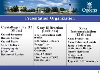

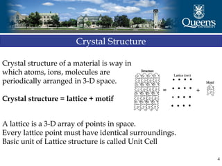
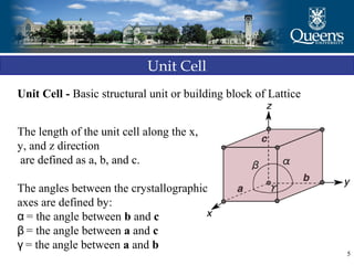
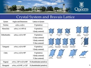
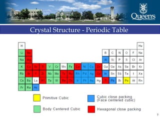
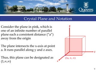
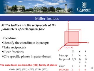
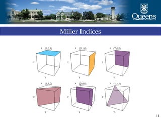
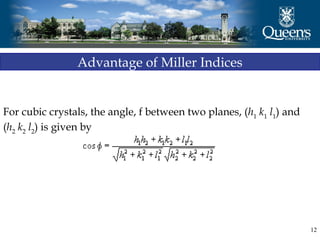
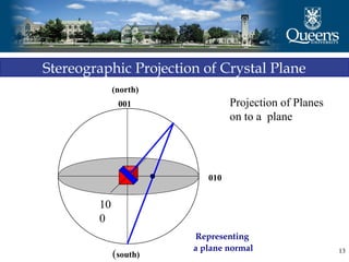
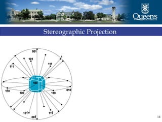

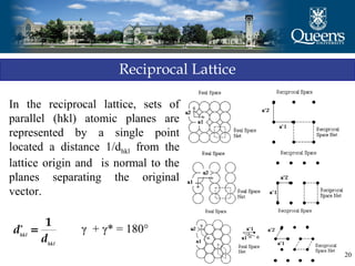
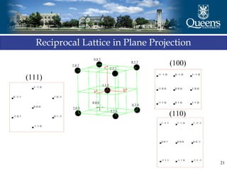

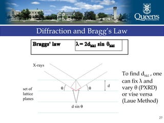
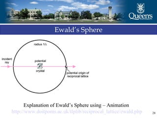
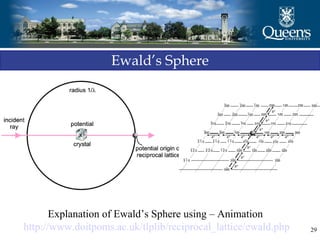
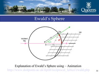


The document discusses crystal structure and x-ray diffraction. It defines crystal structure as the periodic arrangement of atoms in 3D space, with a lattice and motif. The basic unit of the lattice is the unit cell defined by its length along the x, y, and z axes and the angles between them. Miller indices are used to describe crystal planes and are the reciprocals of the plane parameters. Bragg's law relates the diffraction angle to the wavelength and plane spacing. Ewald's sphere construction is used to visualize diffraction and relate the reciprocal lattice to the diffraction pattern.


