


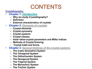

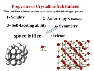
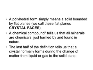
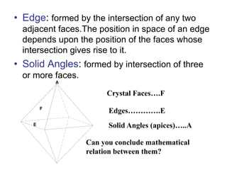
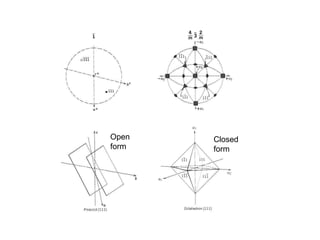
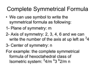
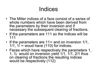
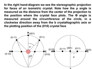
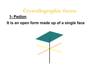
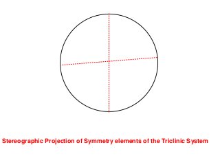
![1- The Primitive Circle is the circle that cross cuts
the sphere and separates it into two equal parts
(North hemisphere and South hemisphere). It is
drawn as solid circle when represents a mirror
plane.
The following rules are applied:
2- All crystal faces are plotted as poles (lines
perpendicular to the crystal face. Thus, angles
between crystal faces are really angles between
poles to crystal faces.
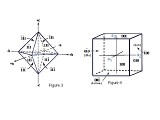
3- The b crystallographic axis is taken as the
starting point. Such an axis will be perpendicular to
the (010) crystal face in any crystal system. The
[010] axis (note zone symbol) or (010) crystal face
will therefore plot at Φ = 0° and ρ = 90°.](https://image.slidesharecdn.com/crystallography-140416050509-phpapp02/85/An-Introduction-to-Crystallography-73-320.jpg)
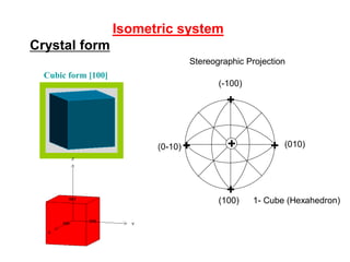
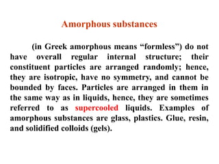
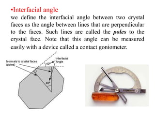
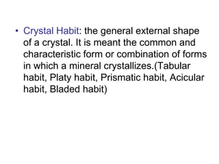
![+
+
+
++
(100)
(010)
(-100)
(0-10)
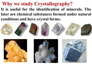
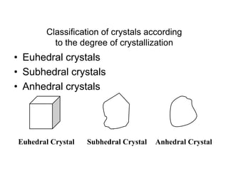
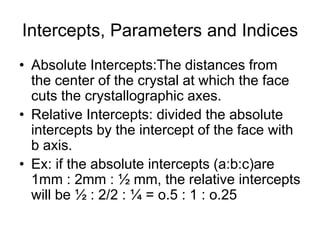
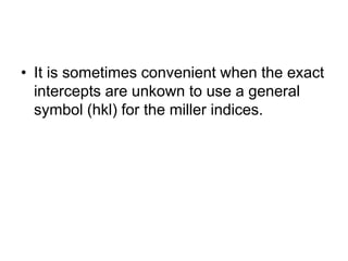
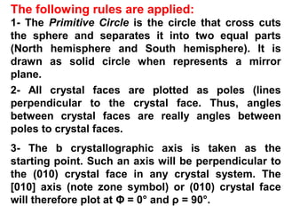
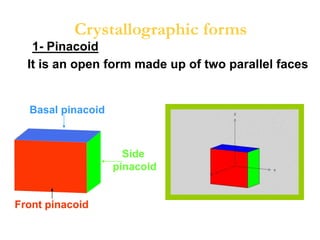
1- Cube (Hexahedron)
Cubic form [100]
Crystal form
Isometric system
Stereographic Projection](https://image.slidesharecdn.com/crystallography-140416050509-phpapp02/85/An-Introduction-to-Crystallography-89-320.jpg)
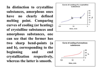
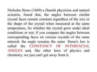
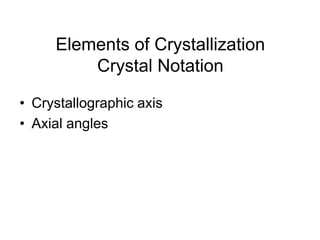
![+
+
+
++
(100)
(010)
(-100)
(0-10)
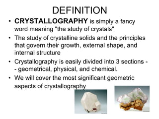
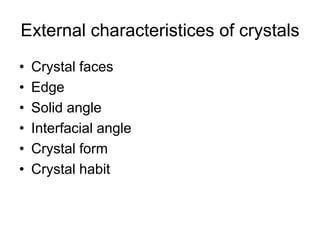
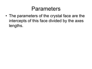
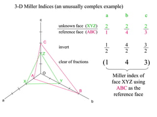
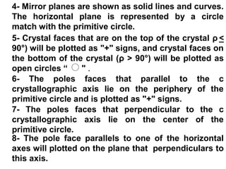
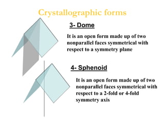
1- Cube (Hexahedron)
+
++
+
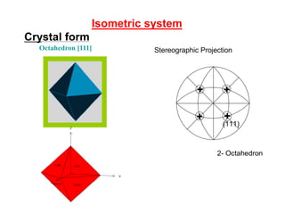
(111)
2- Octahedron
++
+
+
+
Crystal form
Isometric system
Octahedron [111] Stereographic Projection](https://image.slidesharecdn.com/crystallography-140416050509-phpapp02/85/An-Introduction-to-Crystallography-90-320.jpg)
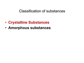
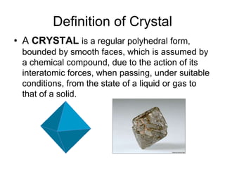
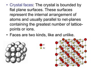
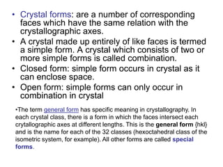
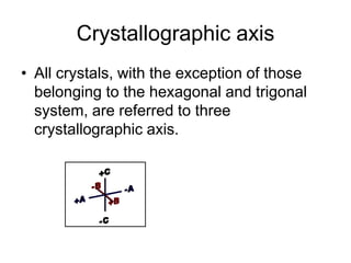
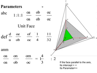
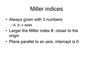
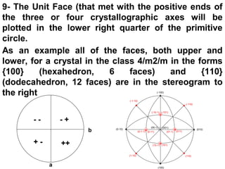
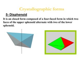
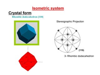
![Crystal form
Isometric system
Rhombic dodecahedron [110]+
+ ++
(100)
(010)10)
1- Cube (Hexahedron)
++
(111)
2- Octahedron
+
++
+
+
+
+
+
(110)
3- Rhombic dodecahedron
ereographic projection of Cubic System
rms.
Stereographic Projection](https://image.slidesharecdn.com/crystallography-140416050509-phpapp02/85/An-Introduction-to-Crystallography-91-320.jpg)
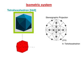
![Isometric system
Tetrahexahedron [hk0]
+
+
+
++
+
+
+
+
+
+
+
+
+
+
+
(210)
4- Tetrahexahedron
+
+ +
++ +
Stereographic Projection](https://image.slidesharecdn.com/crystallography-140416050509-phpapp02/85/An-Introduction-to-Crystallography-93-320.jpg)
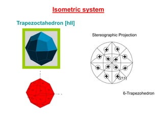
![Isometric system
Trapezoctahedron [hll] +
++
+
+
++
+
+
+
+
(210)
4- Tetrahexahedron
+
+
+
+ ++
+
++ +
+
+
(211)
6-Trapezohedron
Stereographic Projection](https://image.slidesharecdn.com/crystallography-140416050509-phpapp02/85/An-Introduction-to-Crystallography-94-320.jpg)
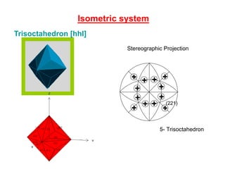
![Trisoctahedron [hhl]
Isometric system
+
+
+
++
+
+
+
+
+
+
+
+
+
+
+
(210)
4- Tetrahexahedron
+
++
+
+
+
+
+
+
+
+
+
(221)
5- Trisoctahedron
+
+ +
+ +
++
+
+
+ +
+
Stereographic Projection](https://image.slidesharecdn.com/crystallography-140416050509-phpapp02/85/An-Introduction-to-Crystallography-95-320.jpg)
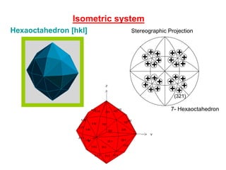
![Hexaoctahedron [hkl]
Isometric system
+
++
+
+
(210)
4- Tetrahexahedron
++ ++ (221)
5- Trisoctahedron
+
+
+
+ ++
+
++ +
+
+
(211)
6-Trapezohedron
+
+
+++
+
+
+
++
++
+
+
+ ++
+
+
+ +
+++
(321)
7- Hexaoctahedron
Stereographic Projection](https://image.slidesharecdn.com/crystallography-140416050509-phpapp02/85/An-Introduction-to-Crystallography-96-320.jpg)
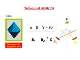
![systemTetragonal
β
Ɣ
α
ca2a1 /
c
a1 a2
Ɣ = 90βα
Ditetragonal –
Bipyramid [hkl]
Class](https://image.slidesharecdn.com/crystallography-140416050509-phpapp02/85/An-Introduction-to-Crystallography-98-320.jpg)
![Basal - pinacoid [001]
systemTetragonalCrystal form
+
1- Basal Pinacoid
(001)
(00-1)
Stereographic Projection](https://image.slidesharecdn.com/crystallography-140416050509-phpapp02/85/An-Introduction-to-Crystallography-104-320.jpg)
![Tetragonal prism of
first order [110]
systemTetragonal
+
1- Basal Pinacoid
(001)
(00-1)
2- Tetragonal prism of 1st order
+
++
+ (110)
+
+
+
Stereographic Projection](https://image.slidesharecdn.com/crystallography-140416050509-phpapp02/85/An-Introduction-to-Crystallography-105-320.jpg)
![Tetragonal prism of
second order [100]
systemTetragonal
ographic projection of Tetragonal
em Forms.
+
1- Basal Pinacoid
(001)
(00-1)
2- Tetragonal prism of 1st order
+
++
+ (110)
3- Tetragonal Prism of 2nd Order
+
+
+
+
(100)
Stereographic Projection](https://image.slidesharecdn.com/crystallography-140416050509-phpapp02/85/An-Introduction-to-Crystallography-106-320.jpg)
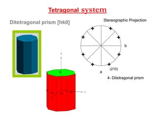
![Ditetragonal prism [hk0]
systemTetragonal
4- Ditetragonal prism
+
+
+
++
+
+
+
(210)
a
b
5-
b
+
+
++
+
+
Stereographic Projection](https://image.slidesharecdn.com/crystallography-140416050509-phpapp02/85/An-Introduction-to-Crystallography-107-320.jpg)
![systemTetragonal
Tetragonal – Bipyramid
of first order [hhl]
4- Ditetragonal prism
+
+
+
++
+
+
+
(210)
a
b
5- Tetragonal bipyramid of 1st Order
a
b
+
++
+
+
+
++
+
(111)
Stereographic Projection](https://image.slidesharecdn.com/crystallography-140416050509-phpapp02/85/An-Introduction-to-Crystallography-108-320.jpg)
![systemTetragonal
Tetragonal – Bipyramid
of second order [h0l]
4- Ditetragonal prism
+
++
+
(210)
a
b
5- Tetragonal bipyramid of 1st Order
a
b
++
6- Tetragonal bipyramid of 2nd Order
a
b
+
+
+
+
7- Ditetragonal bipyramid
a
b
+
+
+
++
+
+
+
(111)
(101)
(211)
Stereographic Projection](https://image.slidesharecdn.com/crystallography-140416050509-phpapp02/85/An-Introduction-to-Crystallography-109-320.jpg)
![systemTetragonal
Ditetragonal –
Bipyramid [hkl]
4- Ditetragonal prism
+
++
+
(210)
a
b
5- T
7- Ditetragonal bipyramid
a
b
+
+
+
++
+
+
+
(211)
Stereographic Projection](https://image.slidesharecdn.com/crystallography-140416050509-phpapp02/85/An-Introduction-to-Crystallography-110-320.jpg)
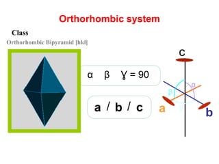
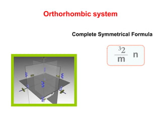
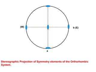
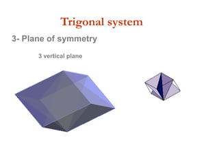
![Orthorhombic system
β
Ɣ
α
cba / /
c
a b
Ɣ = 90βα
Orthorhombic Bipyramid [hkl]
Class](https://image.slidesharecdn.com/crystallography-140416050509-phpapp02/85/An-Introduction-to-Crystallography-112-320.jpg)
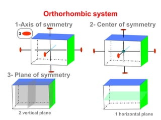
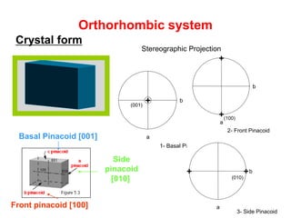
![Orthorhombic system
Crystal form
Side
pinacoid
[010]
Front pinacoid [100]
Basal Pinacoid [001]
1- Basal Pinacoid
a
b+
2- Front Pi
a
b
+
+
(100)
(001)
b++
(010)
Stereographic projection of the Orthorhombic
System Forms.
1- Basal Pinacoid
a
b+
2- Front Pinacoid
a
b
+
+
(100)
(001)
3- Side Pinacoid
a
b++
(010)
Stereographic Projection](https://image.slidesharecdn.com/crystallography-140416050509-phpapp02/85/An-Introduction-to-Crystallography-117-320.jpg)
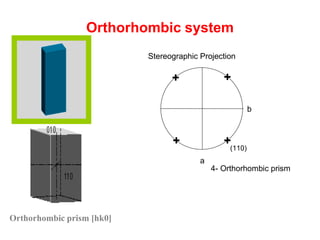
![Orthorhombic prism [hk0]
Orthorhombic system
4- Orthorhombic prism
a
b
+
++
+ (110)
b
++
Stereographic Projection](https://image.slidesharecdn.com/crystallography-140416050509-phpapp02/85/An-Introduction-to-Crystallography-118-320.jpg)
![Orthorhombic system
Orthorhombic front dome [h0l]
4- Orthorhombic prism
a
b
+
++
+ (110)
5- Front dome (b-Dome)
a
b
+
+
(101)
bb
++
Stereographic Projection](https://image.slidesharecdn.com/crystallography-140416050509-phpapp02/85/An-Introduction-to-Crystallography-119-320.jpg)
![Orthorhombic side dome [0kl]
Orthorhombic system
4- Orthorhombic prism
a
b
++ (110)
5- Front dome (b-Dome)
a
b
+
+
(101)
6- Side dome (a-Dome)
a
b++
(011)
7- orthorhombic bipyramid
a
b
+
++
+
Stereographic Projection](https://image.slidesharecdn.com/crystallography-140416050509-phpapp02/85/An-Introduction-to-Crystallography-120-320.jpg)
![Orthorhombic Bipyramid [hkl]
Orthorhombic system
4- Orthorhombic prism
a
b
++ (110)
7- orthorhombic bipyramid
a
b
+
++
+
Stereographic Projection](https://image.slidesharecdn.com/crystallography-140416050509-phpapp02/85/An-Introduction-to-Crystallography-121-320.jpg)
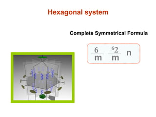
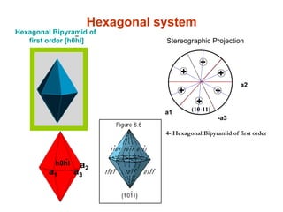
![Hexagonal system
/ca3a2a1
a1
a2
-a
3
c
Ɣ
β α
90βα
Ɣ
Class
Dihexagonal bipyramid [hkwl]](https://image.slidesharecdn.com/crystallography-140416050509-phpapp02/85/An-Introduction-to-Crystallography-123-320.jpg)
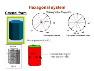
![Hexagonal prism of
first order [1010]
-1010
-
a1
-a3 a2
0001
Hexagonal system
Crystal form
Basal pinacoid [0001]
Stereographic projection of the Hexagonal
System Forms.
a1
a2
-a3
+
1- Hexagonal Pinacoid
(0001)
a1
a2
-a3
2- Hexagonal prism of first order
(10-10)
+
+
+
+
+
+
a1
a2
-a3
3- Hexagonal prism of second order
+
+
++
+
+ (11-20)
Stereographic Projection](https://image.slidesharecdn.com/crystallography-140416050509-phpapp02/85/An-Introduction-to-Crystallography-129-320.jpg)
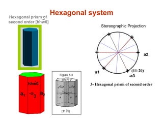
![hhw0
-
a1
-a
3
a2
Hexagonal systemHexagonal prism of
second order [hhw0]
-
Stereographic projection of the Hexagonal
System Forms.
a1
-a3
1- Hexagonal Pinacoid
a1
-a3
2- Hexagonal prism of first order
(10-10)
+
++
a1
a2
-a3
3- Hexagonal prism of second order
+
+
++
+
+ (11-20)
Stereographic Projection](https://image.slidesharecdn.com/crystallography-140416050509-phpapp02/85/An-Introduction-to-Crystallography-130-320.jpg)
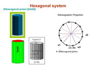
![hkw0
-
Hexagonal system-Dihexagonal prism [hkw0]
Stereographic Projection
a1
a2
-a3
4- Hexagonal Bipyramid of first order
+
(10-11)
++
a1
a2
-a3
6- Dihexagonal prism
(21-30)
+
+
+
+
+
++
+
+
+
+
+](https://image.slidesharecdn.com/crystallography-140416050509-phpapp02/85/An-Introduction-to-Crystallography-131-320.jpg)
![Hexagonal Bipyramid of
first order [h0hl]
-
h0hl
-
a1
-a3
a2
Hexagonal system
a1
a2
-a3
4- Hexagonal Bipyramid of first order
+
(10-11)
+
+
+
+
+
a1
a2
+
+
+
+
+
++
+
+
+
+
+
Stereographic Projection](https://image.slidesharecdn.com/crystallography-140416050509-phpapp02/85/An-Introduction-to-Crystallography-132-320.jpg)
![Hexagonal Bipyramid of
second order [hhwl]
-
hhwl
-
a1 -a3
a2
Hexagonal system
a1
a2
-a3
4- Hexagonal Bipyramid of first order
+
(10-11)
+
+
+
+
+
a1
a2
-a3
5- Hexagonal Bipyramid of second order
+
(11-21)
+
++
+
+
a2
+
+
++
+
+
+ a2
+
+
++
+
+
Stereographic Projection](https://image.slidesharecdn.com/crystallography-140416050509-phpapp02/85/An-Introduction-to-Crystallography-133-320.jpg)
![Dihexagonal bipyramid [hkwl]
-
hkwl
-
Hexagonal system
Stereographic Projection
a1
a2
-a3
4- Hexagonal Bipyramid of first order
+
(10-11)
++
a1
a2
-a3
5- Hexagonal Bipyramid of second order
+
(11-21)
++
+
a1
a2
-a3
6- Dihexagonal prism
(21-30)
+
+
+
+
+
++
+
+
+
+
+ a1
a2
-a3
7- Dihexagonal bipyramid
(21-31)
+
+
+
+
+
++
+
+
+
+
+](https://image.slidesharecdn.com/crystallography-140416050509-phpapp02/85/An-Introduction-to-Crystallography-134-320.jpg)

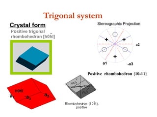
![Positive trigonal
rhombohedron [h0hl]
-
h0hl
-
a1 -a3
a2
Trigonal system
Crystal form
a1 -a3
a2
Positive rhombohedron {10-11}
+
++
a1
a2
+
+
+
+
+
+
Stereographic Projection](https://image.slidesharecdn.com/crystallography-140416050509-phpapp02/85/An-Introduction-to-Crystallography-142-320.jpg)
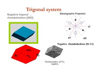
![Negative trigonal
rhombohedron [0kkl]
-
0kkl
-
a1 -a
3
a2
Trigonal system
a1 -a3
a2
a1 -a3
a2
Positive rhombohedron {10-11} Negative rhombohedron {01-11}
+
++
+
+
+
a1 -a3
a2
a1
a2
+
+
+
+
+
+
+
+
+ +
+
+
Stereographic Projection](https://image.slidesharecdn.com/crystallography-140416050509-phpapp02/85/An-Introduction-to-Crystallography-143-320.jpg)
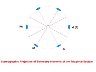
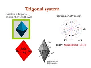
![Positive ditrigonal
scalenohedron [hkwl]
-
hkwl
-
a1 -a3
a2
Trigonal system
Stereographic projection of the Tr
a1 -a3
Positive rhombohedron {10-11}
+
a1 -a3
a2
Positive Scalenohedron {21-31}
+
+
+
+
+
+
Stereographic Projection](https://image.slidesharecdn.com/crystallography-140416050509-phpapp02/85/An-Introduction-to-Crystallography-144-320.jpg)
![Negative ditrigonal
scalenohedron [hkwl]
-
hkwl
-
a1 -a3
a2
Trigonal system
Stereographic projection of the Triagonal System Forms.
a1 -a3 a1 -a3
Positive rhombohedron {10-11} Negative rhombohedron {01-11}
+
+
a1 -a3
a2
a1 -a3
a2
Negative Scalenohedron {12-31}Positive Scalenohedron {21-31}
+
+
+
+
+
+
+
+
+ +
+
+
Stereographic Projection](https://image.slidesharecdn.com/crystallography-140416050509-phpapp02/85/An-Introduction-to-Crystallography-145-320.jpg)
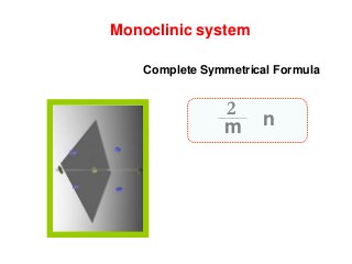
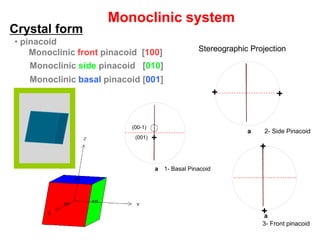
![Monoclinic front pinacoid [100]
Monoclinic side pinacoid [010]
Monoclinic basal pinacoid [001]
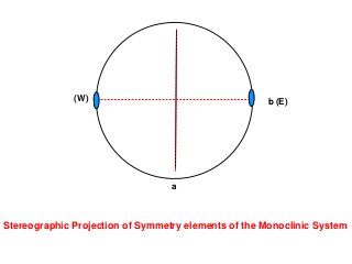
Monoclinic system
Stereographic Projection
• pinacoid
Crystal form
1- Basal Pinacoida
+(001)
2- Side Pinacoida
++
+
(00-1)
Stereographic projection of the Monoclinic
System Forms.
1- Basal Pinacoida
+(001)
2- Side Pinacoida
++
3- Front pinacoid
a
+
+
(00-1)](https://image.slidesharecdn.com/crystallography-140416050509-phpapp02/85/An-Introduction-to-Crystallography-151-320.jpg)
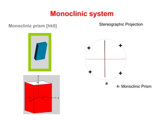
![Monoclinic prism [hk0]
Monoclinic system
Stereographic Projection
m {hk0} or {110}
4- Monoclinic Prism
a
+
++
+
++
(-111)](https://image.slidesharecdn.com/crystallography-140416050509-phpapp02/85/An-Introduction-to-Crystallography-152-320.jpg)
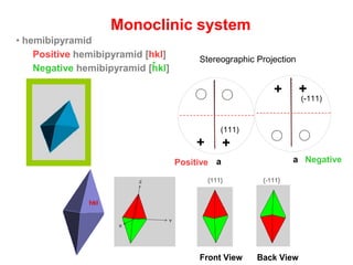
![Positive hemibipyramid [hkl]
Monoclinic system
Positive Hemibipyramid {hkl} or {111}
Negative Hemibipyramid {-hkl} or {-111}
hkl
7- Hemibipyramid
Front View Back View
{111} {-111}
• hemibipyramid
Negative hemibipyramid [hkl]
-
54- Monoclinic Prism
a
++
a
a
+
Positive
(101)
7-Hemibipyramid
a a
++
(111)
++
(-111)
Stereographic Projection
4- M
a
++
7
a
++
(-111)
NegativePositive](https://image.slidesharecdn.com/crystallography-140416050509-phpapp02/85/An-Introduction-to-Crystallography-153-320.jpg)
![5- Side Dome (a-dome)4- Monoclinic Prism
a
+
+
a
++
a a
+ (101)
+(-101)
++
(111)
+
(-111)
-
011
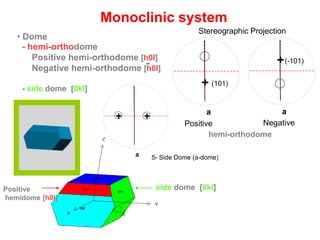
Monoclinic system
• Dome
- hemi-orthodome
Positive hemi-orthodome [h0l]
Negative hemi-orthodome [h0l]
- side dome [0kl]
-
101
011
side dome [0kl]Positive
hemidome [h0l]
5- Side Dome (a-dome)4- Monoclinic Prism
a a
6- Hemi-orthodome
a a
+
Positive
(101)
+
Negative
(-101)
7-Hemibipyramid
a a
++
(111)
++
(-111)
hemi-orthodome
Stereographic Projection](https://image.slidesharecdn.com/crystallography-140416050509-phpapp02/85/An-Introduction-to-Crystallography-154-320.jpg)

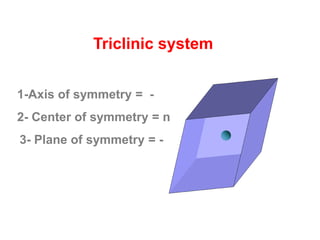
![front pinacoid [100]
side pinacoid [010]
basal pinacoid [001]
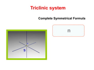
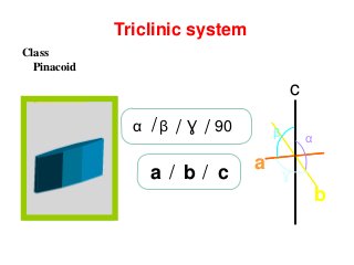
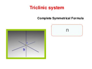
Triclinic system
Crystal form
Stereographic projection of theTriclinic System
Forms.
1- Basal Pinacoida a
a
2- Side Pinacoid
3- Frontl Pinacoid
+
+
+
+
+
Stereographic projection of theTriclinic System
Forms.
1- Basal Pinacoida a
a
2- Side Pinacoid
3- Frontl Pinacoid
+
+
+
+
+
Stereographic Projection](https://image.slidesharecdn.com/crystallography-140416050509-phpapp02/85/An-Introduction-to-Crystallography-159-320.jpg)
![Right hemi-prism [hk0]
Left hemi-prism [hk0]
Triclinic system
-
a a a a
a a
a a
a a
+
+
+
+
+
+ +
+ +
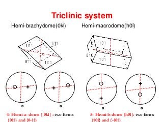
5- Hemi-b-dome {h0l}: two forms
{101} and {-101}
4- Hemi-a- dome { 0kl} : two forms
{011} and {0-11}
6- Hemi-prism{hk0} and {h-k0}
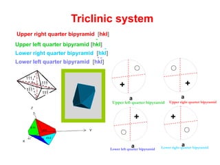
Upper left quarter bipyramid Upper right quarter bipyramid
Lower left quarter bipyramid Lower right quarter bipyramid](https://image.slidesharecdn.com/crystallography-140416050509-phpapp02/85/An-Introduction-to-Crystallography-160-320.jpg)
![Upper right quarter bipyramid [hkl]
Upper left quarter bipyramid [hkl]
Lower right quarter bipyramid [hkl]
Lower left quarter bipyramid [hkl]
-
-
--
Triclinic system
a a
a a
a a
+ +
+ +
+ +
4- Hemi-a- dome { 0kl} : two forms
{011} and {0-11}
Upper left quarter bipyramid Upper right quarter bipyramid
Lower left quarter bipyramid Lower right quarter bipyramid](https://image.slidesharecdn.com/crystallography-140416050509-phpapp02/85/An-Introduction-to-Crystallography-162-320.jpg)

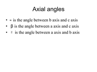
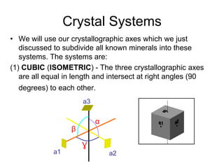
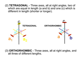
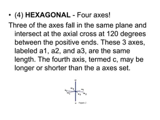
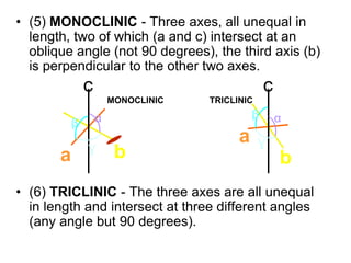
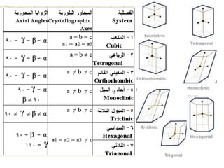
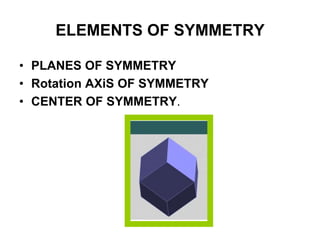
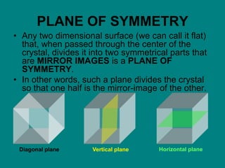
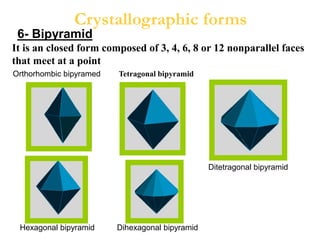
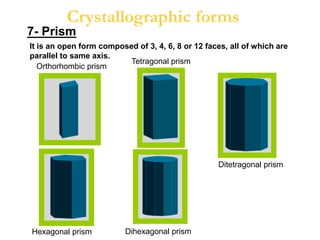
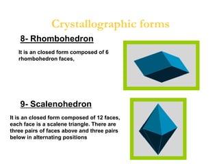
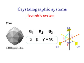
This document provides an introduction to crystallography. It defines crystallography as the study of crystals, which are solid substances with regular internal structures bounded by flat planar faces. The document outlines the key elements of crystals, including crystallographic axes, axial angles, crystal systems, symmetry elements, Miller indices, and habits. It also briefly discusses atomic structure, chemical bonding, and polymorphism as relevant concepts in crystallography.


