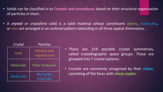
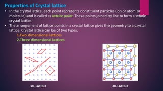
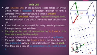
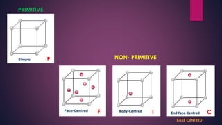
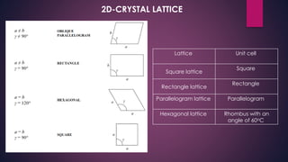
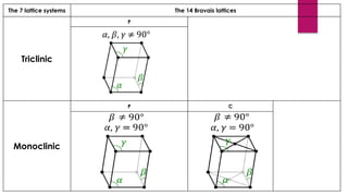
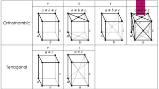
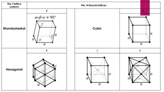
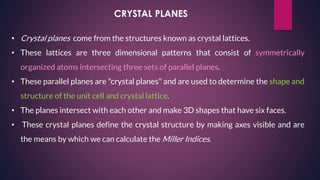
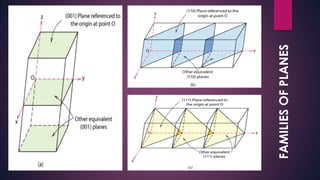
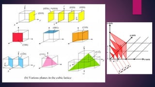
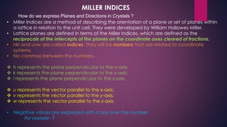
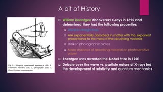
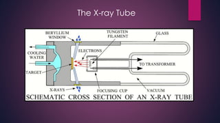
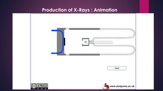
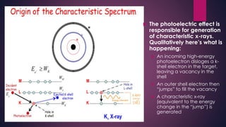
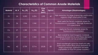
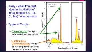
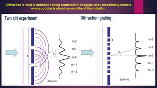
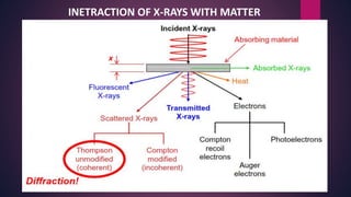
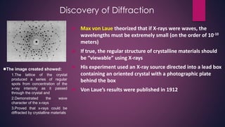
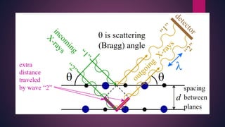
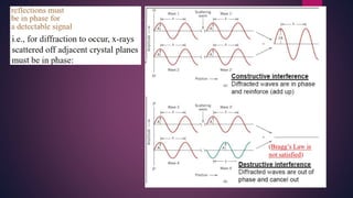
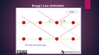
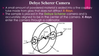
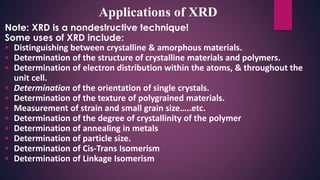
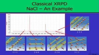
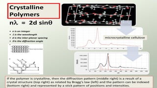
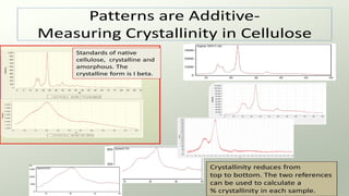
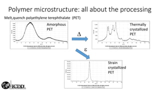
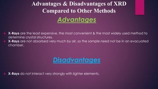
ELEMENTARY
CRYSTALLOGRAPHY &
XRD
BY
DR.A.S.CHARAN
• Solids can be classified in to Crystals and amorphous based on their structural organisation
of particles in them.
• A crystal or crystalline solid is a solid material whose constituent atoms, molecules,
or ions are arranged in an ordered pattern extending in all three spatial dimensions.
Crystal Particles
Ionic
Positive and
negative ions
Molecular Polar molecules
Molecular
Non-polar
molecules
• There are 219 possible crystal symmetries,
called crystallographic space groups. These are
grouped into 7 crystal systems.
• Crystals are commonly recognized by their shape,
consisting of flat faces with sharp angles.
Properties of Crystal lattice
• In the crystal lattice, each point represents constituent particles (ion or atom or
molecule) and is called as lattice point. These points joined by line to form a whole
crystal lattice.
• The arrangement of lattice points in a crystal lattice gives the geometry to a crystal
lattice. Crystal lattice can be of two types,
1.Two dimensional lattices
2.Three dimensional lattices
2D-LATTICE 3D-LATTICE
Unit Cell
• Each smallest unit of the complete space lattice or crystal
lattice, which is repeated in different direction to form a
complete crystal lattice structure is called a unit cell.
• It is just like a thick wall made up of regularly arranged bricks.
Here the thick wall is the crystal lattice and each brick is a unit
cell.
• A unit cell can be explained by using certain parameters.
These parameters are as follows.
• The edge of the unit cell represented by a, b and c. It is
dimensions along the three edges.
• The angle between the edges are represented by α, β and γ.
• The angle between edge b and c is α , the angle between
edge a and c is β, while γ is the angle between edges a and b.
• Thus there are a total of six parameters; a , b , c and α, β and
γ.
PRIMITIVE
NON- PRIMITIVE
BASE CENTRED
P
F I C
Lattice Unit cell
Square lattice
Square
Rectangle lattice
Rectangle
Parallelogram lattice Parallelogram
Hexagonal lattice Rhombus with an
angle of 60oC
2D-CRYSTAL LATTICE
The 7 lattice systems The 14 Bravais lattices
Triclinic
P
Monoclinic
P C
Orthorhombic
P C I F
Tetragonal
P I
The 7 lattice
systems
The 14 Bravais lattices
Rhombohedral
P
Cubic
P
Hexagonal
P I F
CRYSTAL PLANES
• Crystal planes come from the structures known as crystal lattices.
• These lattices are three dimensional patterns that consist of symmetrically
organized atoms intersecting three sets of parallel planes.
• These parallel planes are "crystal planes" and are used to determine the shape and
structure of the unit cell and crystal lattice.
• The planes intersect with each other and make 3D shapes that have six faces.
• These crystal planes define the crystal structure by making axes visible and are
the means by which we can calculate the Miller Indices.
FAMILIESOFPLANES
MILLER INDICES
How do we express Planes and Directions in Crystals ?
• Miller Indices are a method of describing the orientation of a plane or set of planes within
a lattice in relation to the unit cell. They were developed by William Hallowes Miller.
• Lattice planes are defined in terms of the Miller indices, which are defined as the
reciprocals of the intercepts of the planes on the coordinate axes cleared of fractions.
• hkl and uvw are called indices. They will be numbers that are related to coordinate
systems.
• No commas between the numbers.
 h represents the plane perpendicular to the x-axis;
 k represents the plane perpendicular to the y-axis;
 l represents the plane perpendicular to the z-axis.
 u represents the vector parallel to the x-axis;
 v represents the vector parallel to the y-axis;
 w represents the vector parallel to the z-axis.
• Negative values are expressed with a bar over the number
For example : ത3
X-RAY DIFFRACTION
A bit of History
 William Roentgen discovered X-rays in 1895 and
determined they had the following properties
 Travel in straight lines
 Are exponentially absorbed in matter with the exponent
proportional to the mass of the absorbing material
 Darken photographic plates
 Make shadows of absorbing material on photosensitive
paper
 Roentgen was awarded the Nobel Prize in 1901
 Debate over the wave vs. particle nature of X-rays led
the development of relativity and quantum mechanics
The X-ray Tube
Production of X-Rays : Animation
 The photoelectric effect is
responsible for generation
of characteristic x-rays.
Qualitatively here’s what is
happening:
 An incoming high-energy
photoelectron disloges a k-
shell electron in the target,
leaving a vacancy in the
shell
 An outer shell electron then
“jumps” to fill the vacancy
 A characteristic x-ray
(equivalent to the energy
change in the “jump”) is
generated
Characteristics of Common Anode Materials
Material At. # K1 (Å) K2 (Å)
Char
Min
(keV)
Opt kV Advantages (Disadvantages)
Cr 24 2.290 2.294 5.98 40
High resolution for large d-spacings, particularly
organics (High attenuation in air)
Fe 26 1.936 1.940 7.10 40
Most useful for Fe-rich materials where Fe
fluorescence is a problem (Strongly fluoresces
Cr in specimens)
Co 27 1.789 1.793 7.71 40
Useful for Fe-rich materials where Fe
fluorescence is a problem
Cu 29 1.541 1.544 8.86 45
Best overall for most inorganic materials
(Fluoresces Fe and Co K and these elements
in specimens can be problematic)
Mo 42 0.709 0.714 20.00 80
Short wavelength good for small unit cells,
particularly metal alloys (Poor resolution of
large d-spacings; optimal kV exceeds
capabilities of most HV power supplies.)
Diffraction is result of radiation’s being scattered by a regular array of scattering centers
whose spacing is about same as the of the radiation.
INETRACTION OF X-RAYS WITH MATTER
Discovery of Diffraction
 Max von Laue theorized that if X-rays were waves, the
wavelengths must be extremely small (on the order of 10-10
meters)
 If true, the regular structure of crystalline materials should
be “viewable” using X-rays
 His experiment used an X-ray source directed into a lead box
containing an oriented crystal with a photographic plate
behind the box
 Von Laue’s results were published in 1912
The image created showed:
1.The lattice of the crystal
produced a series of regular
spots from concentration of the
x-ray intensity as it passed
through the crystal and
2.Demonstrated the wave
character of the x-rays
3.Proved that x-rays could be
diffracted by crystalline materials
Bragg’s “Extensions” of Diffraction
 Lawrence Bragg and his father W.H. Bragg discovered that diffraction could be treated as
reflection from evenly spaced planes if monochromatic x-radiation was used.
 n X-ray incident upon a sample will either be transmitted, in which case it will continue
along its original direction, or it will be scattered by the electrons of the atoms in the
material. All the atoms in the path of the X-ray beam scatter X-rays.
 We are primarily interested in the peaks formed when scattered X-rays
constructively.interfere. Bragg’s Law: n = 2d sin
where n is an integer
 is the wavelength of the X-radiation
d is the interplanar spacing in the crystalline material and
 is the diffraction angle
 The Bragg Law makes X-ray powder diffraction possible
 In X-ray crystallography, d-spacings and X-ray wavelengths are commonly given in
angstroms
Bragg’s Law-Animated
Diffraction Patterns
X-Ray Diffractıon Methods
Method
Laue Rotating Crystal Powder
Orientation
Single Crystal
Polychromatic
Beam, Fixed Angle
Lattice Constant
Single Crystal
Monchromatic
Beam, Variable Angle
Lattice Parameters
Poly Crystal
Monchromatic
Beam, Variable Angle
Laue Method (Flat Plate Camera)
 The Laue method is mainly used to determine the
orientation of large single crystals while radiation is
reflected from, or transmitted through a fixed crystal.
• The diffracted beams form arrays of spots, that lie on curves on the film.
• The Bragg angle is fixed
for every set of planes in the crystal. Each set of planes picks out &
diffracts the particular wavelength from the white radiation that satisfies
the Bragg law for the values of d & θ involved.
Laue Method (Flat Plate Camera)
Bragg’s X-ray spectrometer
Bragg’s Ionization spectrometerBragg’s spectrometer
 In the rotating crystal method, a single crystal is mounted with an axis
normal to a monochromatic x-ray beam. A cylindrical film is placed around
it & the crystal is rotated about the chosen axis.
 As the crystal rotates, Sets of lattice planes will at some point make the
correct Bragg angle for the monochromatic incident beam, & at that point a
diffracted beam will be formed.
 The Lattice constant of the crystal can be determined with this method. For
a given wavelength λ if the angle θ at which a reflection occurs is known, d
can be determined by using Bragg’s Law.
•
Rotating Crystal Method
2 2 2
a
d
h k l

 2 sind n 
 The reflected beams are located on the surfaces of imaginary cones. By recording the diffraction
patterns (both angles & intensities) for various crystal orientations, one can determine the shape & size of
unit cell as well as the arrangement of atoms inside the cell.
Rotating Crystal Method
 If a powdered crystal is used instead of a single crystal, then there is no need to rotate it,
because there will always be some small crystals at an orientation for which diffraction is
permitted. Here a monochromatic X-ray beam is incident on a powdered or polycrystalline
sample.
 Useful for samples that are difficult to obtain in single crystal form.
 The powder method is used to determine the lattice parameters accurately. Lattice
parameters are the magnitudes of the primitive vectors a, b and c which define the unit
cell for the crystal.
 For every set of crystal planes, by chance, one or more crystals will be in the correct
orientation to give the correct Bragg angle to satisfy Bragg's equation. Every crystal plane is
thus capable of diffraction.
 Each diffraction line is made up of a large number of small spots, each from a separate
crystal. Each spot is so small as to give the appearance of a continuous line.
The Powder Method
The Powder Method-Animation 1
The Powder Method-Animation 2
 A small amount of powdered material is sealed into a fine capillary
tube made from glass that does not diffract X-Rays.
 The sample is placed in the Debye Scherrer camera and is
accurately aligned to be in the center of the camera. X-Rays
enter the camera through a collimator.
Debye Scherer Camera
Debye Scherer Camera-Animation
Note: XRD is a nondestructive technique!
Some uses of XRD include:
 Distinguishing between crystalline & amorphous materials.
 Determination of the structure of crystalline materials and polymers.
 Determination of electron distribution within the atoms, & throughout the
unit cell.
 Determination of the orientation of single crystals.
 Determination of the texture of polygrained materials.
 Measurement of strain and small grain size…..etc.
 Determination of the degree of crystallinity of the polymer
 Determination of annealing in metals
 Determination of particle size.
 Determination of Cis-Trans Isomerism
 Determination of Linkage Isomerism
Applications of XRD
Relationship between crystalline structure and X-ray
data: peak positions, intensities and widths
PEAK POSITION:
The positions of the peaks gives us information that can be used to determine the cell
parameters.
Using Bragg's Law, the peak positions can be theoretically calculated.
For a cubic unit cell:
PEAK INTENSITY:
The intensities of the peaks gives us information about the chemical elements
that are present in the crystal, including their locations in the unit cell.
PEAK WIDTH:
The peak width β in radians is inversely proportional to the crystallite size L
perpendicular to h k l plane. Whilst small crystals are the most common cause of
line broadening but other defects can also cause peak widths to increase.
XRD OF POLYMERS
• Polymers come in many forms. They can be crystalline, microcrystalline
or amorphous.
• In a single polymer, you often find all three forms depending on how the
polymer was made and processed, frequently, forms are mixed in a
single sample.
• Polymers, like other crystalline solids, can also have polymorphs,
polytypes, and all types of solid state molecular arrangements.
XRDOFQUARTZCRYSTALS
Advantages
 X-Rays are the least expensive, the most convenient & the most widely used method to
determine crystal structures.
 X-Rays are not absorbed very much by air, so the sample need not be in an evacuated
chamber.
Disadvantages
 X-Rays do not interact very strongly with lighter elements.
Advantages & Disadvantages of XRD
Compared to Other Methods
THANKS FOR ATTENTION

X-ray diffraction by Dr.A S Charan

  • 1.
  • 2.
    • Solids canbe classified in to Crystals and amorphous based on their structural organisation of particles in them. • A crystal or crystalline solid is a solid material whose constituent atoms, molecules, or ions are arranged in an ordered pattern extending in all three spatial dimensions. Crystal Particles Ionic Positive and negative ions Molecular Polar molecules Molecular Non-polar molecules • There are 219 possible crystal symmetries, called crystallographic space groups. These are grouped into 7 crystal systems. • Crystals are commonly recognized by their shape, consisting of flat faces with sharp angles.
  • 3.
    Properties of Crystallattice • In the crystal lattice, each point represents constituent particles (ion or atom or molecule) and is called as lattice point. These points joined by line to form a whole crystal lattice. • The arrangement of lattice points in a crystal lattice gives the geometry to a crystal lattice. Crystal lattice can be of two types, 1.Two dimensional lattices 2.Three dimensional lattices 2D-LATTICE 3D-LATTICE
  • 4.
    Unit Cell • Eachsmallest unit of the complete space lattice or crystal lattice, which is repeated in different direction to form a complete crystal lattice structure is called a unit cell. • It is just like a thick wall made up of regularly arranged bricks. Here the thick wall is the crystal lattice and each brick is a unit cell. • A unit cell can be explained by using certain parameters. These parameters are as follows. • The edge of the unit cell represented by a, b and c. It is dimensions along the three edges. • The angle between the edges are represented by α, β and γ. • The angle between edge b and c is α , the angle between edge a and c is β, while γ is the angle between edges a and b. • Thus there are a total of six parameters; a , b , c and α, β and γ.
  • 5.
  • 6.
    Lattice Unit cell Squarelattice Square Rectangle lattice Rectangle Parallelogram lattice Parallelogram Hexagonal lattice Rhombus with an angle of 60oC 2D-CRYSTAL LATTICE
  • 7.
    The 7 latticesystems The 14 Bravais lattices Triclinic P Monoclinic P C
  • 8.
    Orthorhombic P C IF Tetragonal P I
  • 9.
    The 7 lattice systems The14 Bravais lattices Rhombohedral P Cubic P Hexagonal P I F
  • 10.
    CRYSTAL PLANES • Crystalplanes come from the structures known as crystal lattices. • These lattices are three dimensional patterns that consist of symmetrically organized atoms intersecting three sets of parallel planes. • These parallel planes are "crystal planes" and are used to determine the shape and structure of the unit cell and crystal lattice. • The planes intersect with each other and make 3D shapes that have six faces. • These crystal planes define the crystal structure by making axes visible and are the means by which we can calculate the Miller Indices.
  • 11.
  • 13.
    MILLER INDICES How dowe express Planes and Directions in Crystals ? • Miller Indices are a method of describing the orientation of a plane or set of planes within a lattice in relation to the unit cell. They were developed by William Hallowes Miller. • Lattice planes are defined in terms of the Miller indices, which are defined as the reciprocals of the intercepts of the planes on the coordinate axes cleared of fractions. • hkl and uvw are called indices. They will be numbers that are related to coordinate systems. • No commas between the numbers.  h represents the plane perpendicular to the x-axis;  k represents the plane perpendicular to the y-axis;  l represents the plane perpendicular to the z-axis.  u represents the vector parallel to the x-axis;  v represents the vector parallel to the y-axis;  w represents the vector parallel to the z-axis. • Negative values are expressed with a bar over the number For example : ത3
  • 14.
  • 15.
    A bit ofHistory  William Roentgen discovered X-rays in 1895 and determined they had the following properties  Travel in straight lines  Are exponentially absorbed in matter with the exponent proportional to the mass of the absorbing material  Darken photographic plates  Make shadows of absorbing material on photosensitive paper  Roentgen was awarded the Nobel Prize in 1901  Debate over the wave vs. particle nature of X-rays led the development of relativity and quantum mechanics
  • 17.
  • 18.
  • 19.
     The photoelectriceffect is responsible for generation of characteristic x-rays. Qualitatively here’s what is happening:  An incoming high-energy photoelectron disloges a k- shell electron in the target, leaving a vacancy in the shell  An outer shell electron then “jumps” to fill the vacancy  A characteristic x-ray (equivalent to the energy change in the “jump”) is generated
  • 20.
    Characteristics of CommonAnode Materials Material At. # K1 (Å) K2 (Å) Char Min (keV) Opt kV Advantages (Disadvantages) Cr 24 2.290 2.294 5.98 40 High resolution for large d-spacings, particularly organics (High attenuation in air) Fe 26 1.936 1.940 7.10 40 Most useful for Fe-rich materials where Fe fluorescence is a problem (Strongly fluoresces Cr in specimens) Co 27 1.789 1.793 7.71 40 Useful for Fe-rich materials where Fe fluorescence is a problem Cu 29 1.541 1.544 8.86 45 Best overall for most inorganic materials (Fluoresces Fe and Co K and these elements in specimens can be problematic) Mo 42 0.709 0.714 20.00 80 Short wavelength good for small unit cells, particularly metal alloys (Poor resolution of large d-spacings; optimal kV exceeds capabilities of most HV power supplies.)
  • 22.
    Diffraction is resultof radiation’s being scattered by a regular array of scattering centers whose spacing is about same as the of the radiation.
  • 23.
  • 24.
    Discovery of Diffraction Max von Laue theorized that if X-rays were waves, the wavelengths must be extremely small (on the order of 10-10 meters)  If true, the regular structure of crystalline materials should be “viewable” using X-rays  His experiment used an X-ray source directed into a lead box containing an oriented crystal with a photographic plate behind the box  Von Laue’s results were published in 1912 The image created showed: 1.The lattice of the crystal produced a series of regular spots from concentration of the x-ray intensity as it passed through the crystal and 2.Demonstrated the wave character of the x-rays 3.Proved that x-rays could be diffracted by crystalline materials
  • 25.
    Bragg’s “Extensions” ofDiffraction  Lawrence Bragg and his father W.H. Bragg discovered that diffraction could be treated as reflection from evenly spaced planes if monochromatic x-radiation was used.  n X-ray incident upon a sample will either be transmitted, in which case it will continue along its original direction, or it will be scattered by the electrons of the atoms in the material. All the atoms in the path of the X-ray beam scatter X-rays.  We are primarily interested in the peaks formed when scattered X-rays constructively.interfere. Bragg’s Law: n = 2d sin where n is an integer  is the wavelength of the X-radiation d is the interplanar spacing in the crystalline material and  is the diffraction angle  The Bragg Law makes X-ray powder diffraction possible  In X-ray crystallography, d-spacings and X-ray wavelengths are commonly given in angstroms
  • 28.
  • 29.
  • 30.
    X-Ray Diffractıon Methods Method LaueRotating Crystal Powder Orientation Single Crystal Polychromatic Beam, Fixed Angle Lattice Constant Single Crystal Monchromatic Beam, Variable Angle Lattice Parameters Poly Crystal Monchromatic Beam, Variable Angle
  • 31.
    Laue Method (FlatPlate Camera)  The Laue method is mainly used to determine the orientation of large single crystals while radiation is reflected from, or transmitted through a fixed crystal. • The diffracted beams form arrays of spots, that lie on curves on the film. • The Bragg angle is fixed for every set of planes in the crystal. Each set of planes picks out & diffracts the particular wavelength from the white radiation that satisfies the Bragg law for the values of d & θ involved.
  • 32.
    Laue Method (FlatPlate Camera)
  • 33.
    Bragg’s X-ray spectrometer Bragg’sIonization spectrometerBragg’s spectrometer
  • 34.
     In therotating crystal method, a single crystal is mounted with an axis normal to a monochromatic x-ray beam. A cylindrical film is placed around it & the crystal is rotated about the chosen axis.  As the crystal rotates, Sets of lattice planes will at some point make the correct Bragg angle for the monochromatic incident beam, & at that point a diffracted beam will be formed.  The Lattice constant of the crystal can be determined with this method. For a given wavelength λ if the angle θ at which a reflection occurs is known, d can be determined by using Bragg’s Law. • Rotating Crystal Method 2 2 2 a d h k l   2 sind n 
  • 35.
     The reflectedbeams are located on the surfaces of imaginary cones. By recording the diffraction patterns (both angles & intensities) for various crystal orientations, one can determine the shape & size of unit cell as well as the arrangement of atoms inside the cell. Rotating Crystal Method
  • 36.
     If apowdered crystal is used instead of a single crystal, then there is no need to rotate it, because there will always be some small crystals at an orientation for which diffraction is permitted. Here a monochromatic X-ray beam is incident on a powdered or polycrystalline sample.  Useful for samples that are difficult to obtain in single crystal form.  The powder method is used to determine the lattice parameters accurately. Lattice parameters are the magnitudes of the primitive vectors a, b and c which define the unit cell for the crystal.  For every set of crystal planes, by chance, one or more crystals will be in the correct orientation to give the correct Bragg angle to satisfy Bragg's equation. Every crystal plane is thus capable of diffraction.  Each diffraction line is made up of a large number of small spots, each from a separate crystal. Each spot is so small as to give the appearance of a continuous line. The Powder Method
  • 37.
  • 38.
  • 39.
     A smallamount of powdered material is sealed into a fine capillary tube made from glass that does not diffract X-Rays.  The sample is placed in the Debye Scherrer camera and is accurately aligned to be in the center of the camera. X-Rays enter the camera through a collimator. Debye Scherer Camera
  • 40.
  • 41.
    Note: XRD isa nondestructive technique! Some uses of XRD include:  Distinguishing between crystalline & amorphous materials.  Determination of the structure of crystalline materials and polymers.  Determination of electron distribution within the atoms, & throughout the unit cell.  Determination of the orientation of single crystals.  Determination of the texture of polygrained materials.  Measurement of strain and small grain size…..etc.  Determination of the degree of crystallinity of the polymer  Determination of annealing in metals  Determination of particle size.  Determination of Cis-Trans Isomerism  Determination of Linkage Isomerism Applications of XRD
  • 42.
    Relationship between crystallinestructure and X-ray data: peak positions, intensities and widths PEAK POSITION: The positions of the peaks gives us information that can be used to determine the cell parameters. Using Bragg's Law, the peak positions can be theoretically calculated. For a cubic unit cell:
  • 43.
    PEAK INTENSITY: The intensitiesof the peaks gives us information about the chemical elements that are present in the crystal, including their locations in the unit cell. PEAK WIDTH: The peak width β in radians is inversely proportional to the crystallite size L perpendicular to h k l plane. Whilst small crystals are the most common cause of line broadening but other defects can also cause peak widths to increase.
  • 44.
    XRD OF POLYMERS •Polymers come in many forms. They can be crystalline, microcrystalline or amorphous. • In a single polymer, you often find all three forms depending on how the polymer was made and processed, frequently, forms are mixed in a single sample. • Polymers, like other crystalline solids, can also have polymorphs, polytypes, and all types of solid state molecular arrangements.
  • 45.
  • 56.
    Advantages  X-Rays arethe least expensive, the most convenient & the most widely used method to determine crystal structures.  X-Rays are not absorbed very much by air, so the sample need not be in an evacuated chamber. Disadvantages  X-Rays do not interact very strongly with lighter elements. Advantages & Disadvantages of XRD Compared to Other Methods
  • 57.