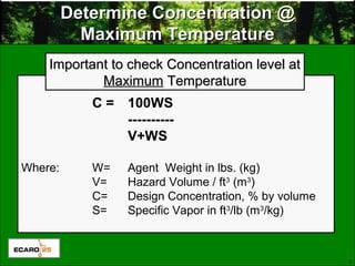
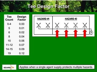
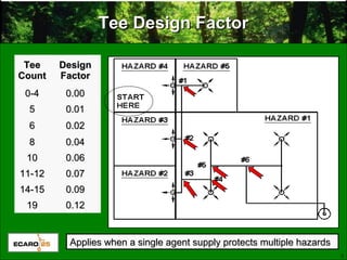
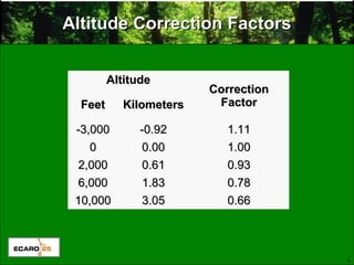
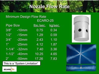
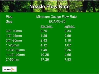
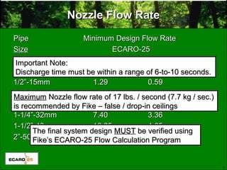
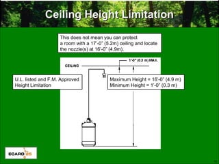
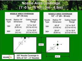
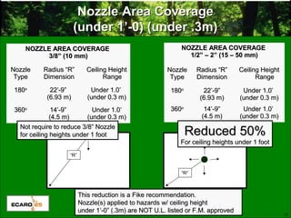
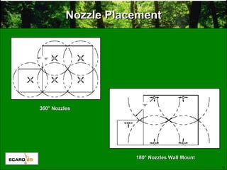
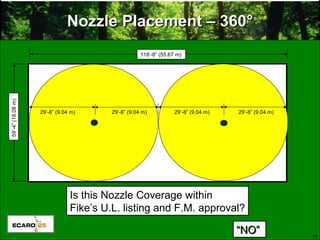
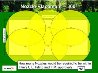
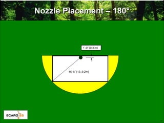
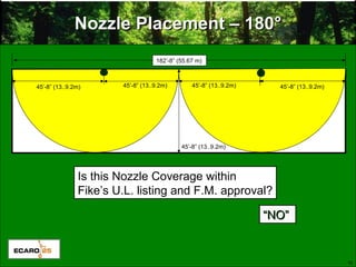
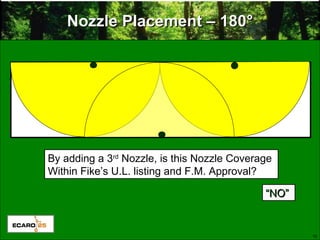
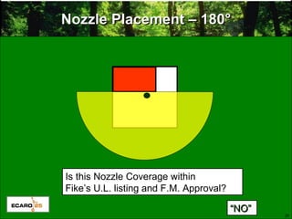
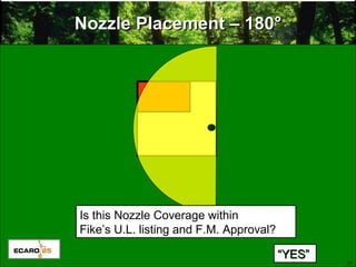
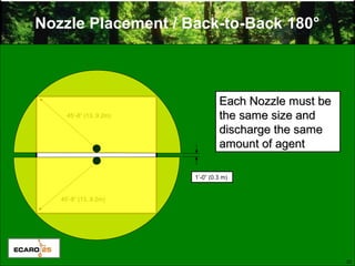
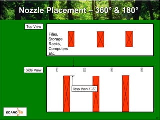
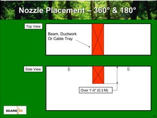
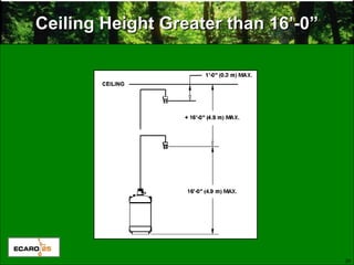
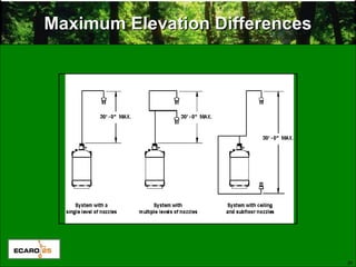
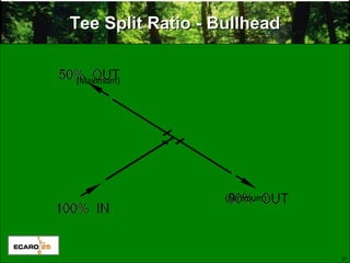
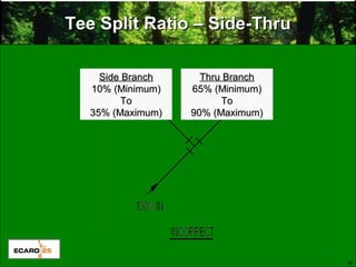
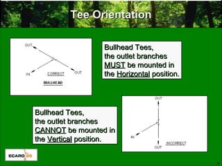
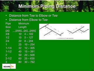
Basic Requirements of FireBasic Requirements of Fire
Suppression Piping & StorageSuppression Piping & Storage
CylinderCylinder
2
Determine Agent QuantityDetermine Agent Quantity
Hazard Volume = Length x Width x HeightHazard Volume = Length x Width x Height
As a general rule . . .As a general rule . . .
Hazard Volume is calculated on EMPTY / GROSS VolumeHazard Volume is calculated on EMPTY / GROSS Volume
What can be deducted?What can be deducted?
Any item that is Solid, Non-Permeable & Non-RemovableAny item that is Solid, Non-Permeable & Non-Removable
What must be added?What must be added?
Any VolumeAny Volume openopen to hazard i.e. non-dampered ductwork,to hazard i.e. non-dampered ductwork,
uncloseable openings, etc.uncloseable openings, etc.
3
C = 100WS
----------
V+WS
Where: W= Agent Weight in lbs. (kg)
V= Hazard Volume / ft3
(m3
)
C= Design Concentration, % by volume
S= Specific Vapor in ft3
/lb (m3
/kg)
Determine Concentration @Determine Concentration @
Maximum TemperatureMaximum Temperature
Important to check Concentration level atImportant to check Concentration level at
MaximumMaximum TemperatureTemperature
4
Tee Design FactorTee Design Factor
TeeTee
CountCount
DesignDesign
FactorFactor
0-40-4 0.000.00
55 0.010.01
66 0.020.02
88 0.040.04
1010 0.060.06
11-1211-12 0.070.07
14-1514-15 0.090.09
1919 0.120.12
Applies when a single agent supply protects multiple hazardsApplies when a single agent supply protects multiple hazards
5
Tee Design FactorTee Design Factor
TeeTee
CountCount
DesignDesign
FactorFactor
0-40-4 0.000.00
55 0.010.01
66 0.020.02
88 0.040.04
1010 0.060.06
11-1211-12 0.070.07
14-1514-15 0.090.09
1919 0.120.12
Applies when a single agent supply protects multiple hazardsApplies when a single agent supply protects multiple hazards
6
Altitude Correction FactorsAltitude Correction Factors
AltitudeAltitude
CorrectionCorrection
FactorFactorFeetFeet KilometersKilometers
-3,000-3,000 -0.92-0.92 1.111.11
00 0.000.00 1.001.00
2,0002,000 0.610.61 0.930.93
6,0006,000 1.831.83 0.780.78
10,00010,000 3.053.05 0.660.66
7
Nozzle Flow RateNozzle Flow Rate
Minimum Design Flow RateMinimum Design Flow Rate
ECARO-25ECARO-25
Pipe SizePipe Size lbs./sec.lbs./sec. kg/sec.kg/sec.
3/8” -10mm 0.753/8” -10mm 0.75 0.340.34
1/2” -15mm 1.291/2” -15mm 1.29 0.590.59
3/4” -20mm 2.433/4” -20mm 2.43 1.101.10
1” -25mm 4.121” -25mm 4.12 1.871.87
1-1/4” -32mm 7.401-1/4” -32mm 7.40 3.363.36
1-1/2” -40mm 10.251-1/2” -40mm 10.25 4.654.65
2” -50mm 17.262” -50mm 17.26 7.837.83
This is a “System Limitation”This is a “System Limitation”
8
Nozzle Flow RateNozzle Flow Rate
Pipe Minimum Design Flow RatePipe Minimum Design Flow Rate
SizeSize ECARO-25ECARO-25
lbs./sec.lbs./sec. kg/sec.kg/sec.
3/8”-10mm3/8”-10mm 0.750.75 0.340.34
1/2”-15mm1/2”-15mm 1.291.29 0.590.59
3/4”-20mm3/4”-20mm 2.432.43 1.101.10
1”-25mm1”-25mm 4.124.12 1.871.87
1-1/4”-32mm1-1/4”-32mm 7.407.40 3.363.36
1-1/2”-40mm1-1/2”-40mm 10.2510.25 4.654.65
2”-50mm2”-50mm 17.2617.26 7.837.83
9
Nozzle Flow RateNozzle Flow Rate
Pipe Minimum Design Flow RatePipe Minimum Design Flow Rate
SizeSize ECARO-25ECARO-25
lbs./sec.lbs./sec. kg/sec.kg/sec.
3/8”-10mm3/8”-10mm 0.750.75 0.340.34
1/2”-15mm1/2”-15mm 1.291.29 0.590.59
3/4”-20mm3/4”-20mm 2.432.43 1.101.10
1”-25mm1”-25mm 4.124.12 1.871.87
1-1/4”-32mm1-1/4”-32mm 7.407.40 3.363.36
1-1/2”-40mm1-1/2”-40mm 10.2510.25 4.654.65
2”-50mm2”-50mm 17.2617.26 7.837.83
Important Note:Important Note:
Discharge time must be within a range of 6-to-10 seconds.Discharge time must be within a range of 6-to-10 seconds.
MaximumMaximum Nozzle flow rate of 17 lbs. / second (7.7 kg / sec.)Nozzle flow rate of 17 lbs. / second (7.7 kg / sec.)
is recommended by Fike – false / drop-in ceilingsis recommended by Fike – false / drop-in ceilings
The final system designThe final system design MUSTMUST be verified usingbe verified using
Fike’s ECARO-25 Flow Calculation ProgramFike’s ECARO-25 Flow Calculation Program
10
Ceiling Height LimitationCeiling Height Limitation
Maximum Height = 16’-0” (4.9 m)
Minimum Height = 1’-0” (0.3 m)
U.L. listed and F.M. Approved
Height Limitation
This does not mean you can protect
a room with a 17’-0” (5.2m) ceiling and locate
the nozzle(s) at 16’-0” (4.9m).
11
Nozzle Area CoverageNozzle Area Coverage
(1’-0 to 16’-0) (.3m - 4.9m)(1’-0 to 16’-0) (.3m - 4.9m)
NOZZLE AREA COVERAGENOZZLE AREA COVERAGE
1/2” – 2” (25 – 50 mm)1/2” – 2” (25 – 50 mm)
NozzleNozzle
TypeType
Radius “R”Radius “R”
DimensionDimension
Ceiling HeightCeiling Height
RangeRange
180180oo 45’-8”45’-8”
(13.92 m)(13.92 m)
1.0’ to 16.0’1.0’ to 16.0’
(0.3 to 4.9 m)(0.3 to 4.9 m)
360360oo 29’-8”’29’-8”’
(9.04 m)(9.04 m)
1.0’ to 16.0’1.0’ to 16.0’
(0.3 to 4.9 m)(0.3 to 4.9 m)
3/8” Nozzle Coverage is3/8” Nozzle Coverage is
50% of 1/2” – 2” Nozzles50% of 1/2” – 2” Nozzles
“R”
“R”
NOZZLE AREA COVERAGENOZZLE AREA COVERAGE
3/8” (10 mm)3/8” (10 mm)
NozzleNozzle
TypeType
Radius “R”Radius “R”
DimensionDimension
Ceiling HeightCeiling Height
RangeRange
180180oo 22’-9”22’-9”
(6.93 m)(6.93 m)
1.0’ to 16.0’1.0’ to 16.0’
(0.3 to 4.9 m)(0.3 to 4.9 m)
360360oo 14’-9”14’-9”
(4.5 m)(4.5 m)
1.0’ to 16.0’1.0’ to 16.0’
(0.3 to 4.9 m)(0.3 to 4.9 m)
40’-0”
44’-0”
12
Nozzle Area CoverageNozzle Area Coverage
(under 1’-0) (under .3m)(under 1’-0) (under .3m)
“R”
“R”
NOZZLE AREA COVERAGENOZZLE AREA COVERAGE
3/8” (10 mm)3/8” (10 mm)
NozzleNozzle
TypeType
Radius “R”Radius “R”
DimensionDimension
Ceiling HeightCeiling Height
RangeRange
180180oo
22’-9”22’-9”
(6.93 m)(6.93 m)
Under 1.0’Under 1.0’
(under 0.3 m)(under 0.3 m)
360360oo
14’-9”14’-9”
(4.5 m)(4.5 m)
Under 1.0’Under 1.0’
(under 0.3 m)(under 0.3 m)
NOZZLE AREA COVERAGENOZZLE AREA COVERAGE
1/2” – 2” (15 – 50 mm)1/2” – 2” (15 – 50 mm)
NozzleNozzle
TypeType
Radius “R”Radius “R”
DimensionDimension
Ceiling HeightCeiling Height
RangeRange
180180oo
22’-9”22’-9”
(6.93 m)(6.93 m)
Under 1.0’Under 1.0’
(under 0.3 m)(under 0.3 m)
360360oo
14’-9”14’-9”
(4.5 m)(4.5 m)
Under 1.0’Under 1.0’
(under 0.3 m)(under 0.3 m)
Reduced 50%Reduced 50%
For ceiling heights under 1 footFor ceiling heights under 1 foot
Not require to reduce 3/8” NozzleNot require to reduce 3/8” Nozzle
for ceiling heights under 1 footfor ceiling heights under 1 foot
This reduction is a Fike recommendation.This reduction is a Fike recommendation.
Nozzle(s) applied to hazards w/ ceiling heightNozzle(s) applied to hazards w/ ceiling height
under 1’-0” (.3m) are NOT U.L. listed or F.M. approvedunder 1’-0” (.3m) are NOT U.L. listed or F.M. approved
13
Nozzle PlacementNozzle Placement
180° Nozzles Wall Mount180° Nozzles Wall Mount
360° Nozzles360° Nozzles
14
Nozzle Placement – 360Nozzle Placement – 360°°
29’-8” (9.4 m)
15
Nozzle Placement – 360Nozzle Placement – 360°°
Is this Nozzle Coverage within
Fike’s U.L. listing and F.M. approval?
29’-8” (9.04 m)
““NO”NO”
118’-8” (55.67 m)
29’-8” (9.04 m)29’-8” (9.04 m) 29’-8” (9.04 m)
59’-4”(18.08m)
16
Nozzle Placement – 360Nozzle Placement – 360°°
118’-8” (55.67 m)
59’-4”(18.08m)
How many Nozzles would be required to be within
Fike’s U.L. listing and F.M. approval?
““6”6”
17
Nozzle Placement – 180Nozzle Placement – 180°°
45’-8” (13..9.2m)
1’-0” (0.3 m)
18
Nozzle Placement – 180Nozzle Placement – 180°°
Is this Nozzle Coverage within
Fike’s U.L. listing and F.M. approval?
45’-8” (13..9.2m)
““NO”NO”
45’-8” (13..9.2m)
45’-8” (13..9.2m)
182’-8” (55.67 m)
45’-8” (13..9.2m) 45’-8” (13..9.2m)
19
Nozzle Placement – 180Nozzle Placement – 180°°
By adding a 3rd
Nozzle, is this Nozzle Coverage
Within Fike’s U.L. listing and F.M. Approval?
““NO”NO”
20
Nozzle Placement – 180Nozzle Placement – 180°°
““NO”NO”
Is this Nozzle Coverage within
Fike’s U.L. listing and F.M. Approval?
21
Nozzle Placement – 180Nozzle Placement – 180°°
““YES”YES”
Is this Nozzle Coverage within
Fike’s U.L. listing and F.M. Approval?
22
Nozzle Placement / Back-to-Back 180°
Each Nozzle must beEach Nozzle must be
the same size andthe same size and
discharge the samedischarge the same
amount of agentamount of agent
45’-8” (13..9.2m)
1’-0” (0.3 m)
45’-8” (13..9.2m)
23
Nozzle Placement – 360Nozzle Placement – 360° & 180°° & 180°
Top View
Side View
Files,
Storage
Racks,
Computers
Etc.
less than 1’-6”
24
Nozzle Placement – 360Nozzle Placement – 360° & 180°° & 180°
Top View
Side View
Beam, Ductwork
Or Cable Tray
Over 1’-0” (0.3 M)
25
Ceiling Height Greater than 16’-0”Ceiling Height Greater than 16’-0”
26
Maximum Elevation DifferencesMaximum Elevation Differences
27
Tee Split Ratio - BullheadTee Split Ratio - Bullhead
(Maximum)
(Minimum)
28
Tee Split Ratio – Side-ThruTee Split Ratio – Side-Thru
Side BranchSide Branch
10% (Minimum)10% (Minimum)
ToTo
35% (Maximum)35% (Maximum)
Thru BranchThru Branch
65% (Minimum)65% (Minimum)
ToTo
90% (Maximum)90% (Maximum)
29
Tee OrientationTee Orientation
Side-Thru Tees,Side-Thru Tees,
the outlet branchesthe outlet branches
CANNOTCANNOT be mounted inbe mounted in
thethe VerticalVertical position.position.
Side-Thru Tees,Side-Thru Tees,
the outlet branchesthe outlet branches
MUSTMUST be mounted inbe mounted in
thethe HorizontalHorizontal position.position.
30
Tee OrientationTee Orientation
Bullhead Tees,Bullhead Tees,
the outlet branchesthe outlet branches
MUSTMUST be mounted inbe mounted in
thethe HorizontalHorizontal position.position.
Bullhead Tees,Bullhead Tees,
the outlet branchesthe outlet branches
CANNOTCANNOT be mounted inbe mounted in
thethe VerticalVertical position.position.
31
Tee OrientationTee Orientation
Bullhead Tees,Bullhead Tees,
the inlet branchthe inlet branch
CANCAN be mounted inbe mounted in
thethe HorizontalHorizontal position.position.
Side-Thru Tees,Side-Thru Tees,
the outlet branchesthe outlet branches
CANNOTCANNOT be mounted inbe mounted in
thethe VerticalVertical position.position.
32
Minimum Piping DistanceMinimum Piping Distance
• Distance from Tee to Elbow or TeeDistance from Tee to Elbow or Tee
• Distance from Elbow to TeeDistance from Elbow to Tee
PipePipe MinimumMinimum
SizeSize LengthLength
(in)(in) (mm) (in) (mm)(mm) (in) (mm)
3/83/8 1010 4 – 1024 – 102
1/21/2 1515 5 – 1275 – 127
3/43/4 2020 8 – 2048 – 204
11 2525 10 – 25410 – 254
1-1/41-1/4 3232 12 – 30512 – 305
1-1/21-1/2 4040 15 – 38115 – 381
22 5050 20 – 50820 – 508
2-1/22-1/2 6060 25 – 63525 – 635
33 8080 30 – 76230 – 762
Any Questions?Any Questions?
about Tee Splitsabout Tee Splits
34
Minimum Flow Rates in Pipe NetworkMinimum Flow Rates in Pipe Network
Pipe Minimum Design Flow RatePipe Minimum Design Flow Rate
SizeSize ECARO-25ECARO-25
lbs./sec.lbs./sec. kg/sec.kg/sec.
3/8”-10mm3/8”-10mm 0.750.75 0.340.34
1/2”-15mm1/2”-15mm 1.291.29 0.590.59
3/4”-20mm3/4”-20mm 2.432.43 1.101.10
1”-25mm1”-25mm 4.124.12 1.871.87
1-1/4”-32mm1-1/4”-32mm 7.407.40 3.363.36
1-1/2”-40mm1-1/2”-40mm 10.2510.25 4.654.65
2”-50mm2”-50mm 17.2617.26 7.837.83
2-1/2”-65mm2-1/2”-65mm 25.0025.00 11.3011.30
3”-80mm3”-80mm 39.0039.00 17.7017.70
4”-100mm4”-100mm 68.0068.00 30.8030.80
6”-150mm6”-150mm 156.00156.00 70.7070.70
Need to be concerned with minimum flow ratesNeed to be concerned with minimum flow rates
when manually estimating pipe sizeswhen manually estimating pipe sizes
or manually entering into flow calc program.or manually entering into flow calc program.

Basic requirement for fire suppression piping - ECARO-25

  • 1.
    Basic Requirements ofFireBasic Requirements of Fire Suppression Piping & StorageSuppression Piping & Storage CylinderCylinder
  • 2.
    2 Determine Agent QuantityDetermineAgent Quantity Hazard Volume = Length x Width x HeightHazard Volume = Length x Width x Height As a general rule . . .As a general rule . . . Hazard Volume is calculated on EMPTY / GROSS VolumeHazard Volume is calculated on EMPTY / GROSS Volume What can be deducted?What can be deducted? Any item that is Solid, Non-Permeable & Non-RemovableAny item that is Solid, Non-Permeable & Non-Removable What must be added?What must be added? Any VolumeAny Volume openopen to hazard i.e. non-dampered ductwork,to hazard i.e. non-dampered ductwork, uncloseable openings, etc.uncloseable openings, etc.
  • 3.
    3 C = 100WS ---------- V+WS Where:W= Agent Weight in lbs. (kg) V= Hazard Volume / ft3 (m3 ) C= Design Concentration, % by volume S= Specific Vapor in ft3 /lb (m3 /kg) Determine Concentration @Determine Concentration @ Maximum TemperatureMaximum Temperature Important to check Concentration level atImportant to check Concentration level at MaximumMaximum TemperatureTemperature
  • 4.
    4 Tee Design FactorTeeDesign Factor TeeTee CountCount DesignDesign FactorFactor 0-40-4 0.000.00 55 0.010.01 66 0.020.02 88 0.040.04 1010 0.060.06 11-1211-12 0.070.07 14-1514-15 0.090.09 1919 0.120.12 Applies when a single agent supply protects multiple hazardsApplies when a single agent supply protects multiple hazards
  • 5.
    5 Tee Design FactorTeeDesign Factor TeeTee CountCount DesignDesign FactorFactor 0-40-4 0.000.00 55 0.010.01 66 0.020.02 88 0.040.04 1010 0.060.06 11-1211-12 0.070.07 14-1514-15 0.090.09 1919 0.120.12 Applies when a single agent supply protects multiple hazardsApplies when a single agent supply protects multiple hazards
  • 6.
    6 Altitude Correction FactorsAltitudeCorrection Factors AltitudeAltitude CorrectionCorrection FactorFactorFeetFeet KilometersKilometers -3,000-3,000 -0.92-0.92 1.111.11 00 0.000.00 1.001.00 2,0002,000 0.610.61 0.930.93 6,0006,000 1.831.83 0.780.78 10,00010,000 3.053.05 0.660.66
  • 7.
    7 Nozzle Flow RateNozzleFlow Rate Minimum Design Flow RateMinimum Design Flow Rate ECARO-25ECARO-25 Pipe SizePipe Size lbs./sec.lbs./sec. kg/sec.kg/sec. 3/8” -10mm 0.753/8” -10mm 0.75 0.340.34 1/2” -15mm 1.291/2” -15mm 1.29 0.590.59 3/4” -20mm 2.433/4” -20mm 2.43 1.101.10 1” -25mm 4.121” -25mm 4.12 1.871.87 1-1/4” -32mm 7.401-1/4” -32mm 7.40 3.363.36 1-1/2” -40mm 10.251-1/2” -40mm 10.25 4.654.65 2” -50mm 17.262” -50mm 17.26 7.837.83 This is a “System Limitation”This is a “System Limitation”
  • 8.
    8 Nozzle Flow RateNozzleFlow Rate Pipe Minimum Design Flow RatePipe Minimum Design Flow Rate SizeSize ECARO-25ECARO-25 lbs./sec.lbs./sec. kg/sec.kg/sec. 3/8”-10mm3/8”-10mm 0.750.75 0.340.34 1/2”-15mm1/2”-15mm 1.291.29 0.590.59 3/4”-20mm3/4”-20mm 2.432.43 1.101.10 1”-25mm1”-25mm 4.124.12 1.871.87 1-1/4”-32mm1-1/4”-32mm 7.407.40 3.363.36 1-1/2”-40mm1-1/2”-40mm 10.2510.25 4.654.65 2”-50mm2”-50mm 17.2617.26 7.837.83
  • 9.
    9 Nozzle Flow RateNozzleFlow Rate Pipe Minimum Design Flow RatePipe Minimum Design Flow Rate SizeSize ECARO-25ECARO-25 lbs./sec.lbs./sec. kg/sec.kg/sec. 3/8”-10mm3/8”-10mm 0.750.75 0.340.34 1/2”-15mm1/2”-15mm 1.291.29 0.590.59 3/4”-20mm3/4”-20mm 2.432.43 1.101.10 1”-25mm1”-25mm 4.124.12 1.871.87 1-1/4”-32mm1-1/4”-32mm 7.407.40 3.363.36 1-1/2”-40mm1-1/2”-40mm 10.2510.25 4.654.65 2”-50mm2”-50mm 17.2617.26 7.837.83 Important Note:Important Note: Discharge time must be within a range of 6-to-10 seconds.Discharge time must be within a range of 6-to-10 seconds. MaximumMaximum Nozzle flow rate of 17 lbs. / second (7.7 kg / sec.)Nozzle flow rate of 17 lbs. / second (7.7 kg / sec.) is recommended by Fike – false / drop-in ceilingsis recommended by Fike – false / drop-in ceilings The final system designThe final system design MUSTMUST be verified usingbe verified using Fike’s ECARO-25 Flow Calculation ProgramFike’s ECARO-25 Flow Calculation Program
  • 10.
    10 Ceiling Height LimitationCeilingHeight Limitation Maximum Height = 16’-0” (4.9 m) Minimum Height = 1’-0” (0.3 m) U.L. listed and F.M. Approved Height Limitation This does not mean you can protect a room with a 17’-0” (5.2m) ceiling and locate the nozzle(s) at 16’-0” (4.9m).
  • 11.
    11 Nozzle Area CoverageNozzleArea Coverage (1’-0 to 16’-0) (.3m - 4.9m)(1’-0 to 16’-0) (.3m - 4.9m) NOZZLE AREA COVERAGENOZZLE AREA COVERAGE 1/2” – 2” (25 – 50 mm)1/2” – 2” (25 – 50 mm) NozzleNozzle TypeType Radius “R”Radius “R” DimensionDimension Ceiling HeightCeiling Height RangeRange 180180oo 45’-8”45’-8” (13.92 m)(13.92 m) 1.0’ to 16.0’1.0’ to 16.0’ (0.3 to 4.9 m)(0.3 to 4.9 m) 360360oo 29’-8”’29’-8”’ (9.04 m)(9.04 m) 1.0’ to 16.0’1.0’ to 16.0’ (0.3 to 4.9 m)(0.3 to 4.9 m) 3/8” Nozzle Coverage is3/8” Nozzle Coverage is 50% of 1/2” – 2” Nozzles50% of 1/2” – 2” Nozzles “R” “R” NOZZLE AREA COVERAGENOZZLE AREA COVERAGE 3/8” (10 mm)3/8” (10 mm) NozzleNozzle TypeType Radius “R”Radius “R” DimensionDimension Ceiling HeightCeiling Height RangeRange 180180oo 22’-9”22’-9” (6.93 m)(6.93 m) 1.0’ to 16.0’1.0’ to 16.0’ (0.3 to 4.9 m)(0.3 to 4.9 m) 360360oo 14’-9”14’-9” (4.5 m)(4.5 m) 1.0’ to 16.0’1.0’ to 16.0’ (0.3 to 4.9 m)(0.3 to 4.9 m) 40’-0” 44’-0”
  • 12.
    12 Nozzle Area CoverageNozzleArea Coverage (under 1’-0) (under .3m)(under 1’-0) (under .3m) “R” “R” NOZZLE AREA COVERAGENOZZLE AREA COVERAGE 3/8” (10 mm)3/8” (10 mm) NozzleNozzle TypeType Radius “R”Radius “R” DimensionDimension Ceiling HeightCeiling Height RangeRange 180180oo 22’-9”22’-9” (6.93 m)(6.93 m) Under 1.0’Under 1.0’ (under 0.3 m)(under 0.3 m) 360360oo 14’-9”14’-9” (4.5 m)(4.5 m) Under 1.0’Under 1.0’ (under 0.3 m)(under 0.3 m) NOZZLE AREA COVERAGENOZZLE AREA COVERAGE 1/2” – 2” (15 – 50 mm)1/2” – 2” (15 – 50 mm) NozzleNozzle TypeType Radius “R”Radius “R” DimensionDimension Ceiling HeightCeiling Height RangeRange 180180oo 22’-9”22’-9” (6.93 m)(6.93 m) Under 1.0’Under 1.0’ (under 0.3 m)(under 0.3 m) 360360oo 14’-9”14’-9” (4.5 m)(4.5 m) Under 1.0’Under 1.0’ (under 0.3 m)(under 0.3 m) Reduced 50%Reduced 50% For ceiling heights under 1 footFor ceiling heights under 1 foot Not require to reduce 3/8” NozzleNot require to reduce 3/8” Nozzle for ceiling heights under 1 footfor ceiling heights under 1 foot This reduction is a Fike recommendation.This reduction is a Fike recommendation. Nozzle(s) applied to hazards w/ ceiling heightNozzle(s) applied to hazards w/ ceiling height under 1’-0” (.3m) are NOT U.L. listed or F.M. approvedunder 1’-0” (.3m) are NOT U.L. listed or F.M. approved
  • 13.
    13 Nozzle PlacementNozzle Placement 180°Nozzles Wall Mount180° Nozzles Wall Mount 360° Nozzles360° Nozzles
  • 14.
    14 Nozzle Placement –360Nozzle Placement – 360°° 29’-8” (9.4 m)
  • 15.
    15 Nozzle Placement –360Nozzle Placement – 360°° Is this Nozzle Coverage within Fike’s U.L. listing and F.M. approval? 29’-8” (9.04 m) ““NO”NO” 118’-8” (55.67 m) 29’-8” (9.04 m)29’-8” (9.04 m) 29’-8” (9.04 m) 59’-4”(18.08m)
  • 16.
    16 Nozzle Placement –360Nozzle Placement – 360°° 118’-8” (55.67 m) 59’-4”(18.08m) How many Nozzles would be required to be within Fike’s U.L. listing and F.M. approval? ““6”6”
  • 17.
    17 Nozzle Placement –180Nozzle Placement – 180°° 45’-8” (13..9.2m) 1’-0” (0.3 m)
  • 18.
    18 Nozzle Placement –180Nozzle Placement – 180°° Is this Nozzle Coverage within Fike’s U.L. listing and F.M. approval? 45’-8” (13..9.2m) ““NO”NO” 45’-8” (13..9.2m) 45’-8” (13..9.2m) 182’-8” (55.67 m) 45’-8” (13..9.2m) 45’-8” (13..9.2m)
  • 19.
    19 Nozzle Placement –180Nozzle Placement – 180°° By adding a 3rd Nozzle, is this Nozzle Coverage Within Fike’s U.L. listing and F.M. Approval? ““NO”NO”
  • 20.
    20 Nozzle Placement –180Nozzle Placement – 180°° ““NO”NO” Is this Nozzle Coverage within Fike’s U.L. listing and F.M. Approval?
  • 21.
    21 Nozzle Placement –180Nozzle Placement – 180°° ““YES”YES” Is this Nozzle Coverage within Fike’s U.L. listing and F.M. Approval?
  • 22.
    22 Nozzle Placement /Back-to-Back 180° Each Nozzle must beEach Nozzle must be the same size andthe same size and discharge the samedischarge the same amount of agentamount of agent 45’-8” (13..9.2m) 1’-0” (0.3 m) 45’-8” (13..9.2m)
  • 23.
    23 Nozzle Placement –360Nozzle Placement – 360° & 180°° & 180° Top View Side View Files, Storage Racks, Computers Etc. less than 1’-6”
  • 24.
    24 Nozzle Placement –360Nozzle Placement – 360° & 180°° & 180° Top View Side View Beam, Ductwork Or Cable Tray Over 1’-0” (0.3 M)
  • 25.
    25 Ceiling Height Greaterthan 16’-0”Ceiling Height Greater than 16’-0”
  • 26.
  • 27.
    27 Tee Split Ratio- BullheadTee Split Ratio - Bullhead (Maximum) (Minimum)
  • 28.
    28 Tee Split Ratio– Side-ThruTee Split Ratio – Side-Thru Side BranchSide Branch 10% (Minimum)10% (Minimum) ToTo 35% (Maximum)35% (Maximum) Thru BranchThru Branch 65% (Minimum)65% (Minimum) ToTo 90% (Maximum)90% (Maximum)
  • 29.
    29 Tee OrientationTee Orientation Side-ThruTees,Side-Thru Tees, the outlet branchesthe outlet branches CANNOTCANNOT be mounted inbe mounted in thethe VerticalVertical position.position. Side-Thru Tees,Side-Thru Tees, the outlet branchesthe outlet branches MUSTMUST be mounted inbe mounted in thethe HorizontalHorizontal position.position.
  • 30.
    30 Tee OrientationTee Orientation BullheadTees,Bullhead Tees, the outlet branchesthe outlet branches MUSTMUST be mounted inbe mounted in thethe HorizontalHorizontal position.position. Bullhead Tees,Bullhead Tees, the outlet branchesthe outlet branches CANNOTCANNOT be mounted inbe mounted in thethe VerticalVertical position.position.
  • 31.
    31 Tee OrientationTee Orientation BullheadTees,Bullhead Tees, the inlet branchthe inlet branch CANCAN be mounted inbe mounted in thethe HorizontalHorizontal position.position. Side-Thru Tees,Side-Thru Tees, the outlet branchesthe outlet branches CANNOTCANNOT be mounted inbe mounted in thethe VerticalVertical position.position.
  • 32.
    32 Minimum Piping DistanceMinimumPiping Distance • Distance from Tee to Elbow or TeeDistance from Tee to Elbow or Tee • Distance from Elbow to TeeDistance from Elbow to Tee PipePipe MinimumMinimum SizeSize LengthLength (in)(in) (mm) (in) (mm)(mm) (in) (mm) 3/83/8 1010 4 – 1024 – 102 1/21/2 1515 5 – 1275 – 127 3/43/4 2020 8 – 2048 – 204 11 2525 10 – 25410 – 254 1-1/41-1/4 3232 12 – 30512 – 305 1-1/21-1/2 4040 15 – 38115 – 381 22 5050 20 – 50820 – 508 2-1/22-1/2 6060 25 – 63525 – 635 33 8080 30 – 76230 – 762
  • 33.
    Any Questions?Any Questions? aboutTee Splitsabout Tee Splits
  • 34.
    34 Minimum Flow Ratesin Pipe NetworkMinimum Flow Rates in Pipe Network Pipe Minimum Design Flow RatePipe Minimum Design Flow Rate SizeSize ECARO-25ECARO-25 lbs./sec.lbs./sec. kg/sec.kg/sec. 3/8”-10mm3/8”-10mm 0.750.75 0.340.34 1/2”-15mm1/2”-15mm 1.291.29 0.590.59 3/4”-20mm3/4”-20mm 2.432.43 1.101.10 1”-25mm1”-25mm 4.124.12 1.871.87 1-1/4”-32mm1-1/4”-32mm 7.407.40 3.363.36 1-1/2”-40mm1-1/2”-40mm 10.2510.25 4.654.65 2”-50mm2”-50mm 17.2617.26 7.837.83 2-1/2”-65mm2-1/2”-65mm 25.0025.00 11.3011.30 3”-80mm3”-80mm 39.0039.00 17.7017.70 4”-100mm4”-100mm 68.0068.00 30.8030.80 6”-150mm6”-150mm 156.00156.00 70.7070.70 Need to be concerned with minimum flow ratesNeed to be concerned with minimum flow rates when manually estimating pipe sizeswhen manually estimating pipe sizes or manually entering into flow calc program.or manually entering into flow calc program.