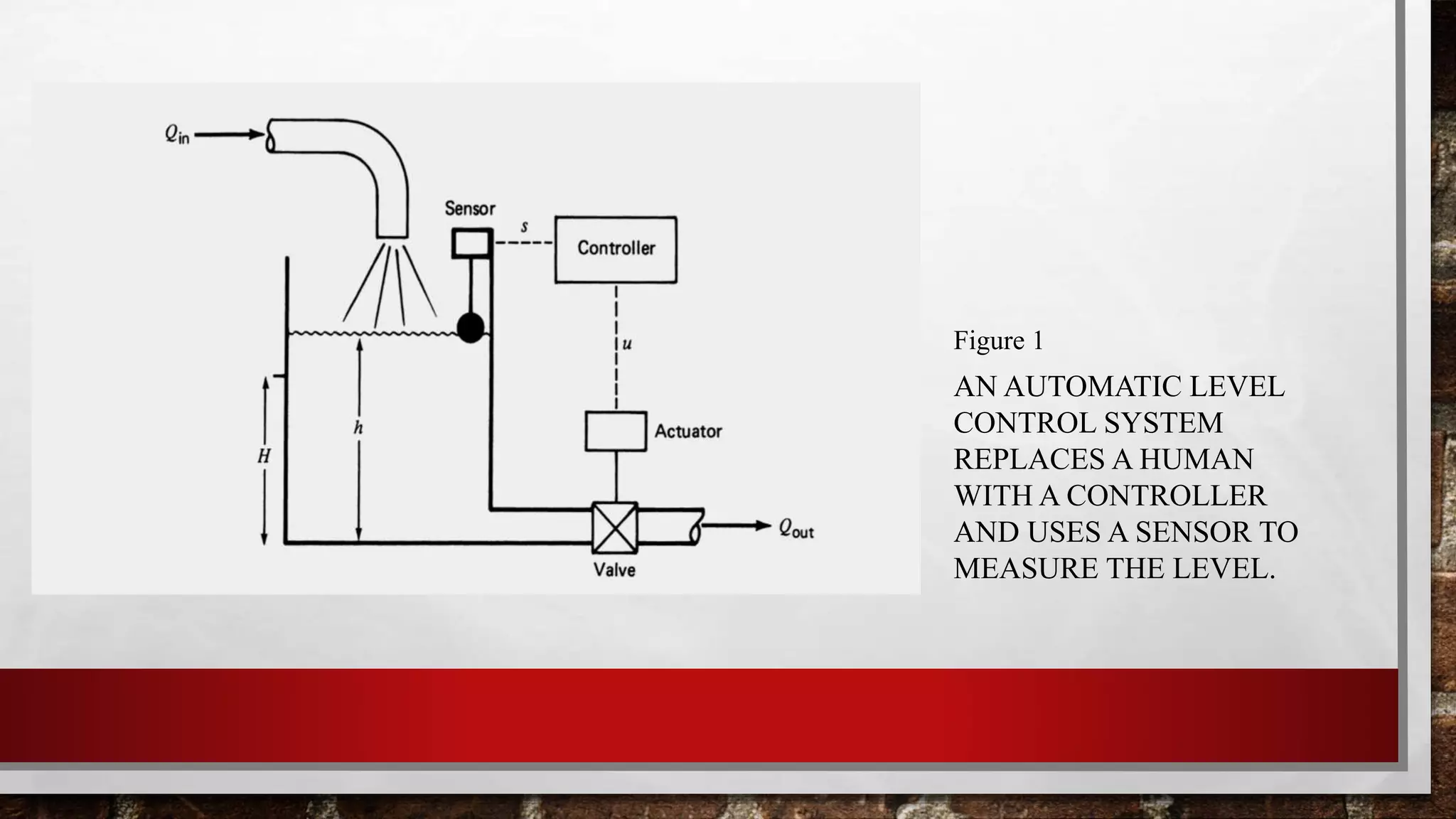
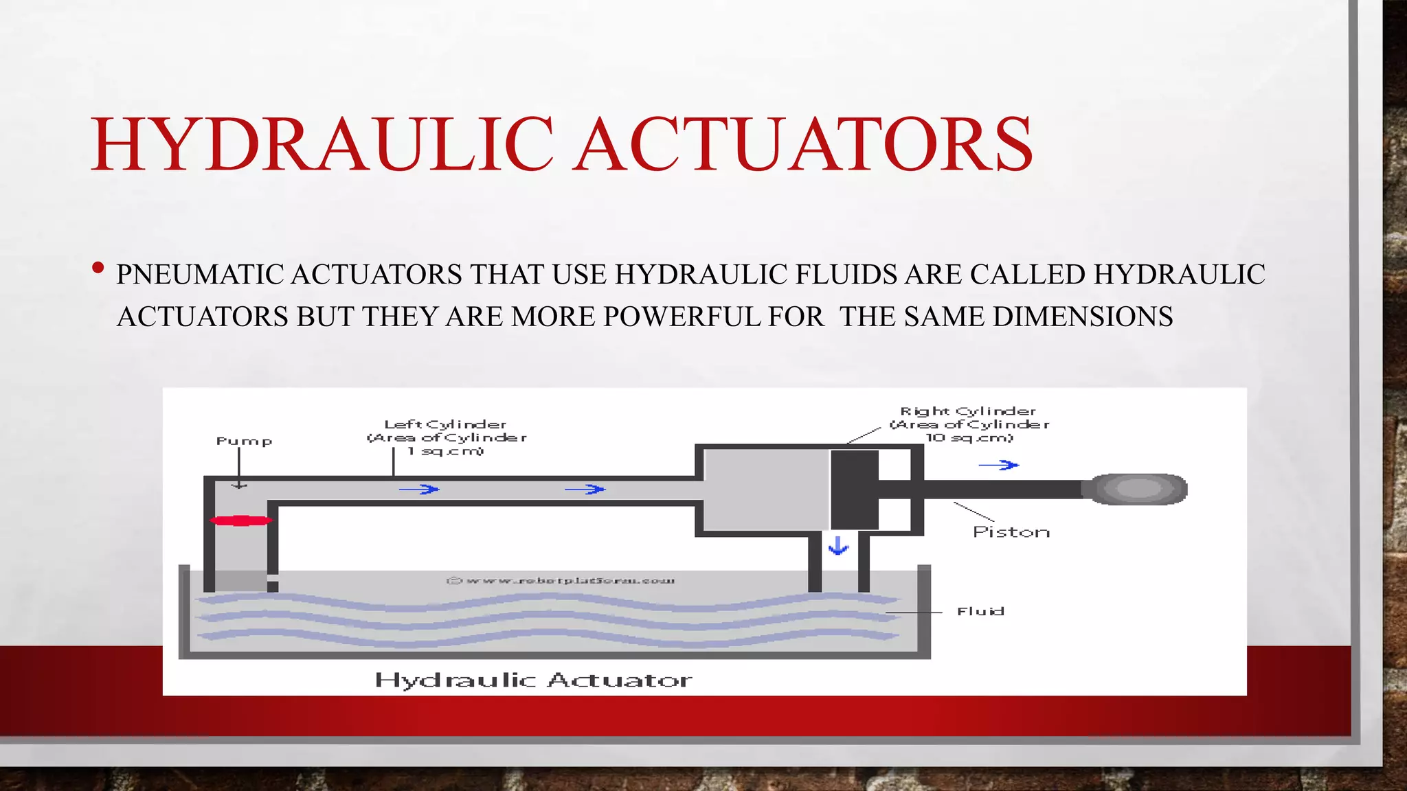
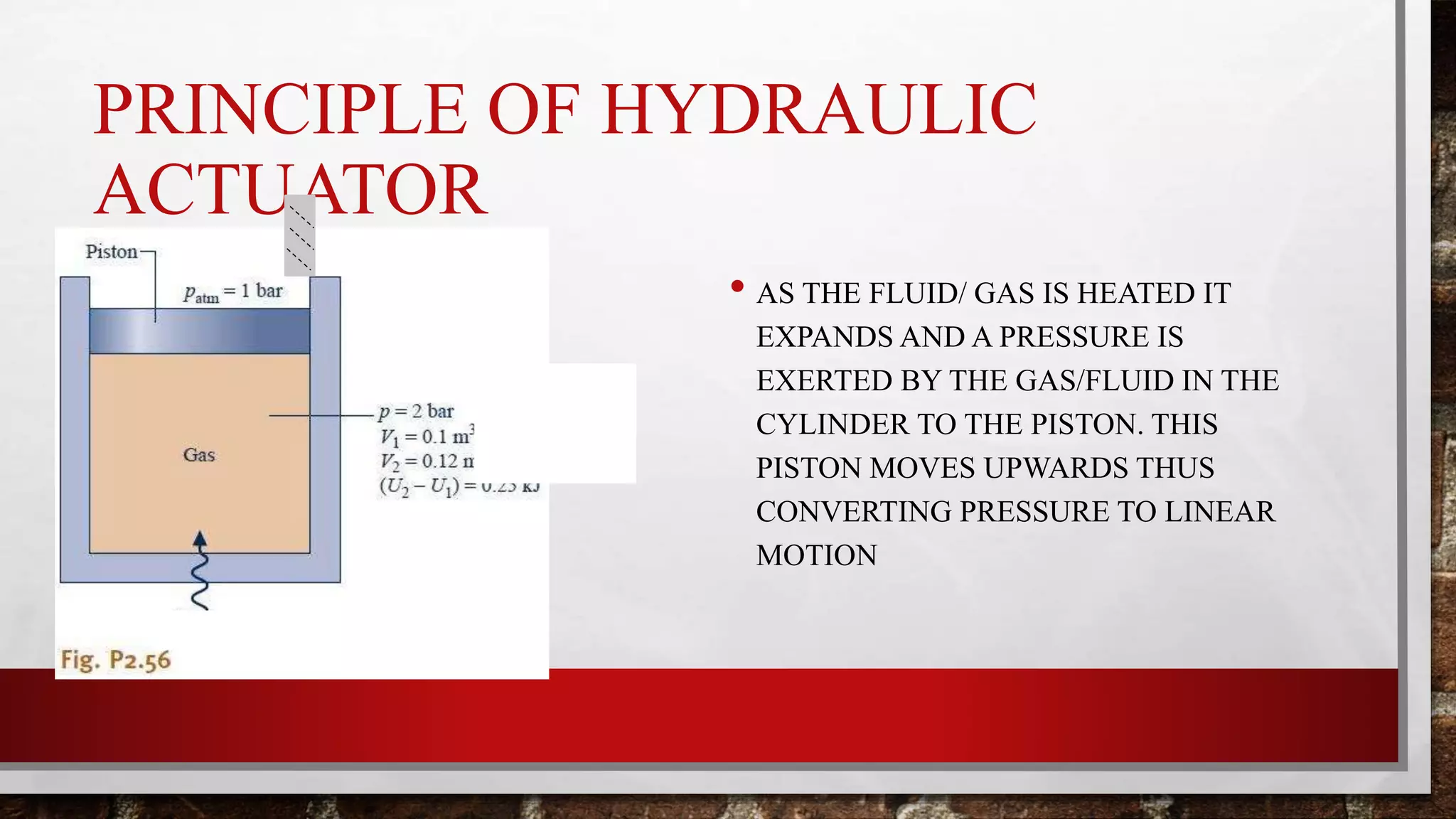
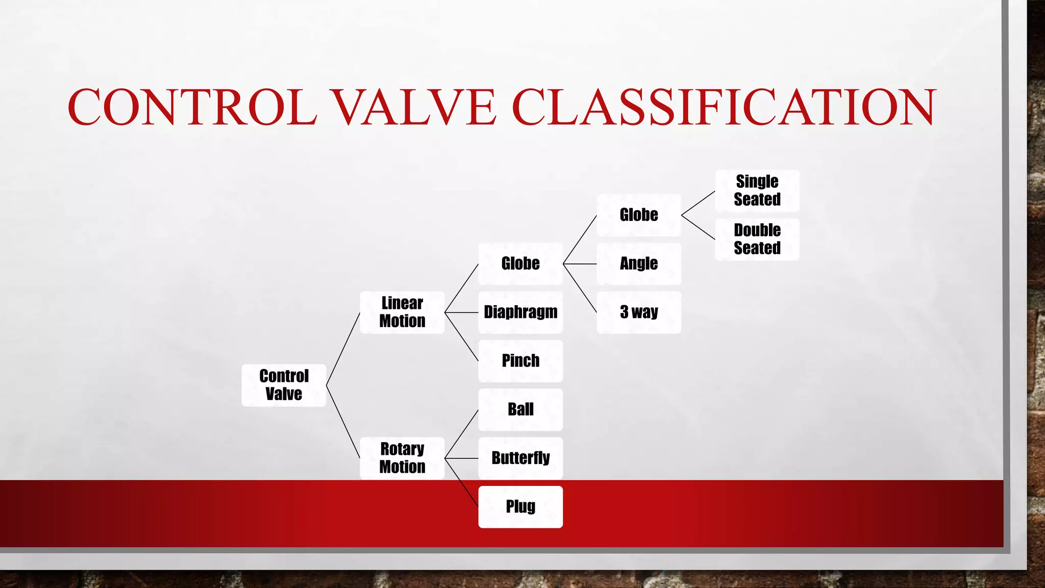
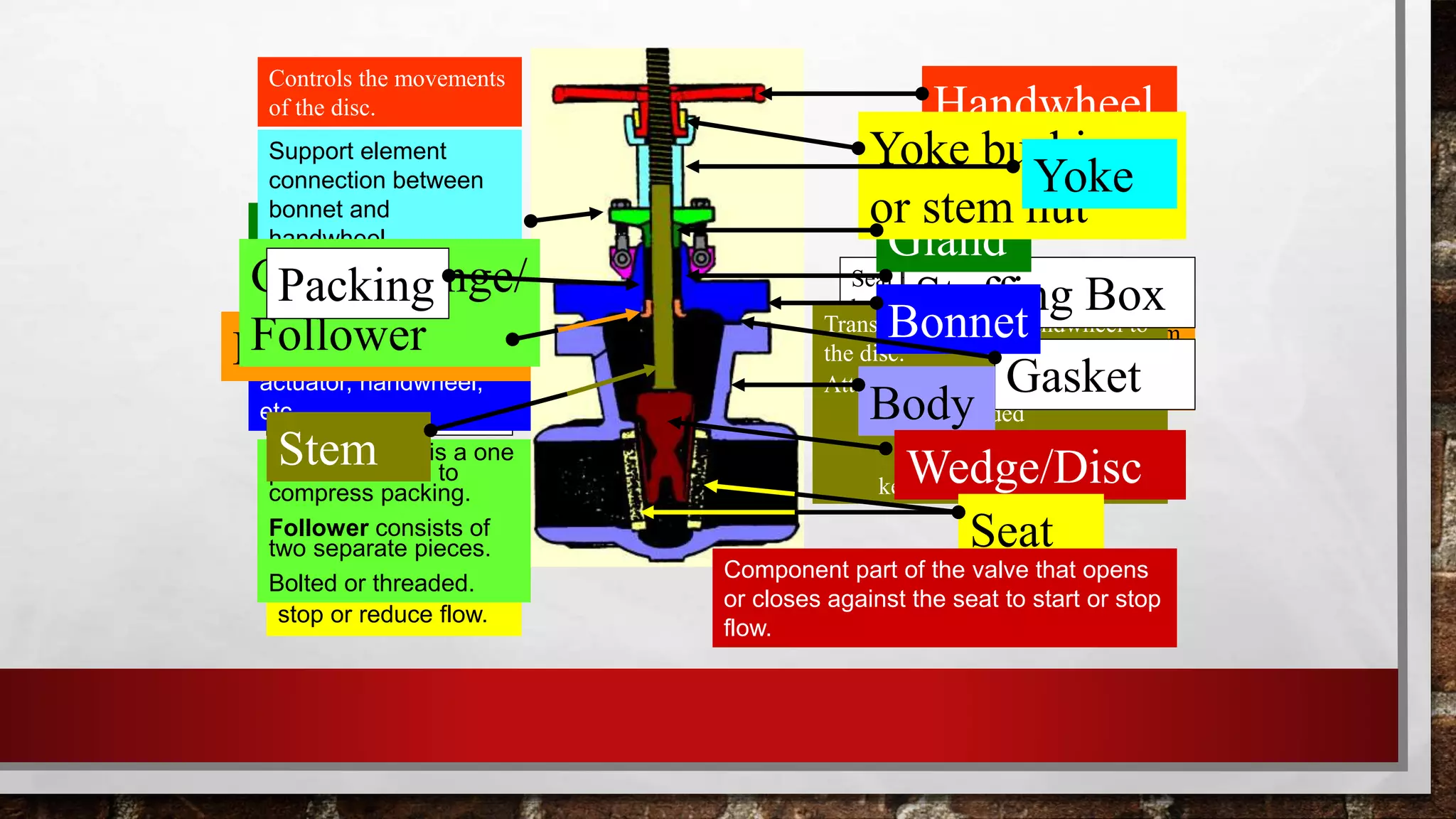
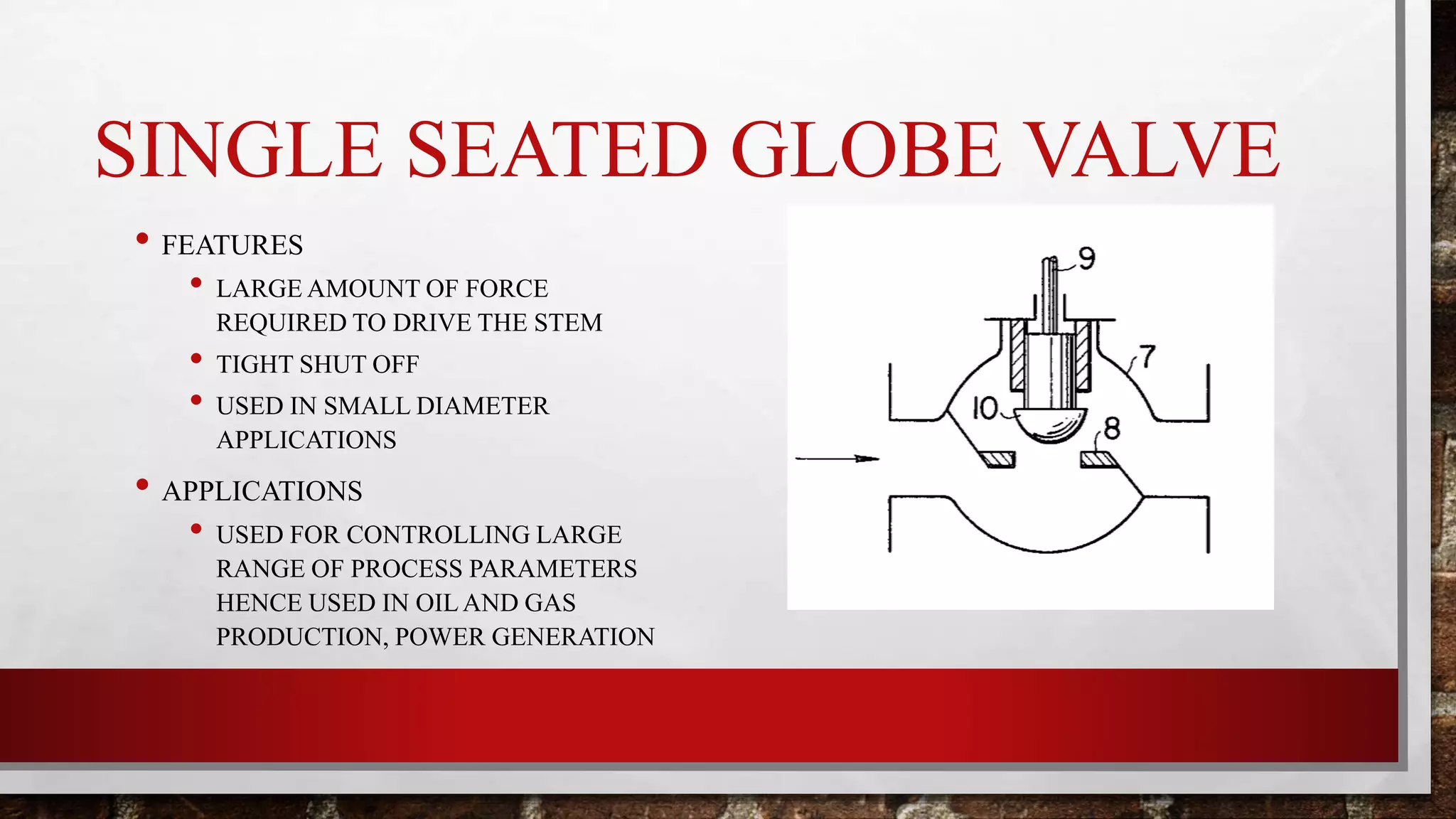
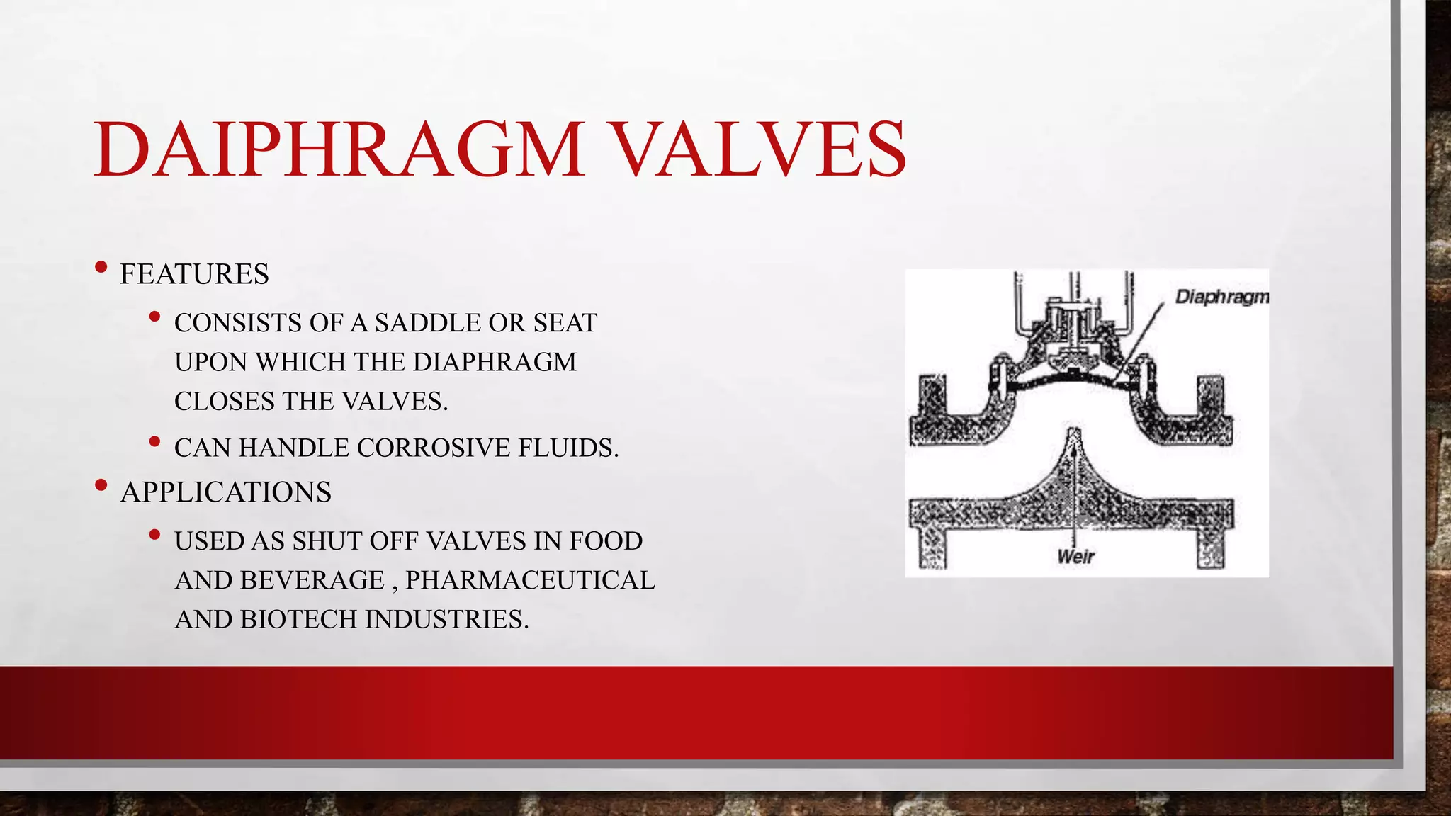
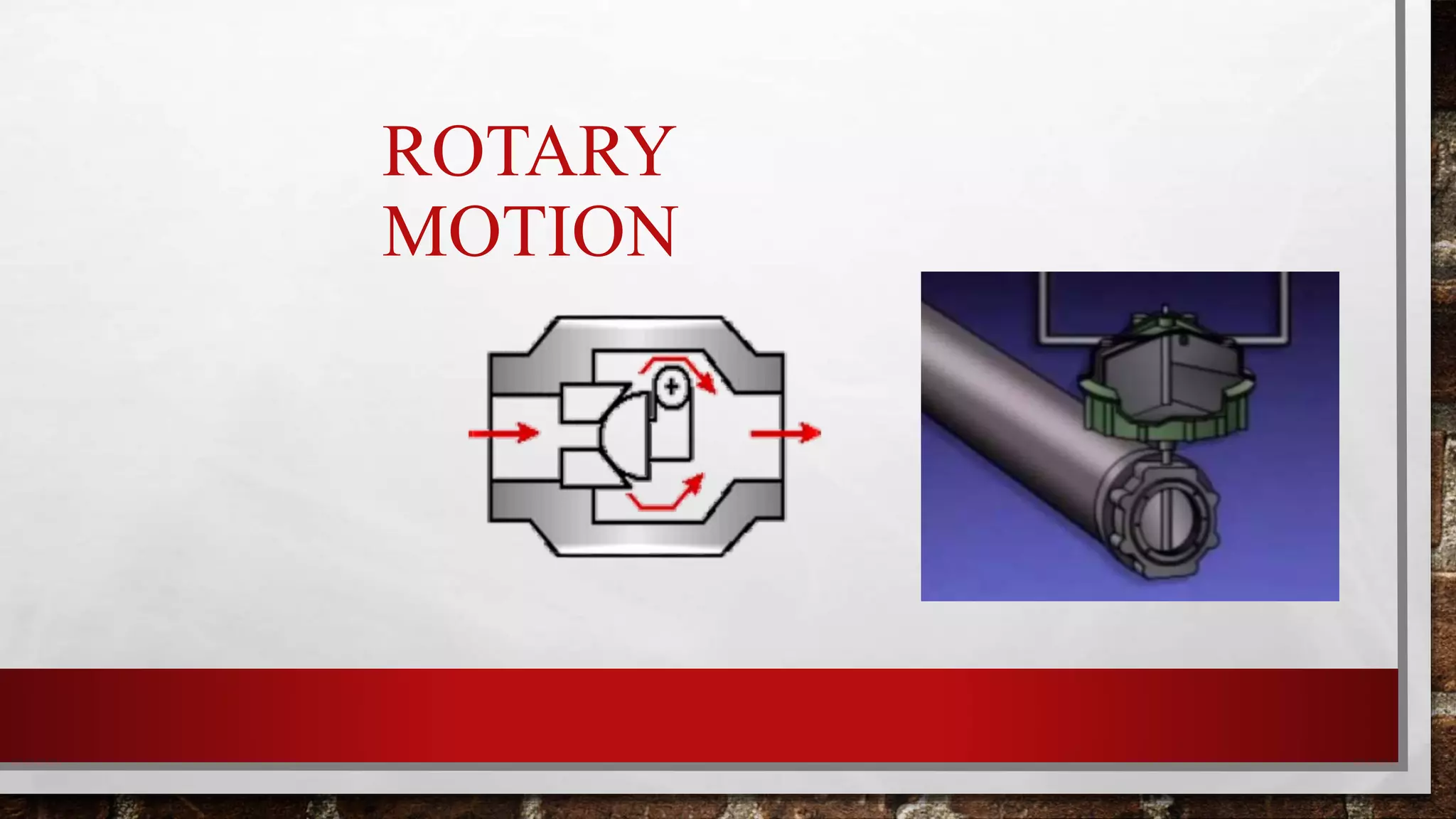
The document discusses control valves, including their purpose, main components, types of actuators (pneumatic, hydraulic, electrical), and types of valves (linear motion like globe valves and rotary motion like ball valves). It provides details on parts of control valves like the actuator, positioner, and body. It also covers topics like valve sizing, flow characteristics, and considerations for control valves like fluid velocity, noise, vibration, and flow direction.
In this day and age of automated computer control valve sizing, the logic and theories behind it are invisible. In his presentation, Al Holton of Allagash Valve & Controls will look at the basic principles that apply and how they affect the application and installation of a wide range of control valve types. He will also review the reasoning behind valve type selection.
Pneumatic control valve
Actual Pneumatic Control Valve
Typical Actuator & Valve
introduction to actuator
Actuator power
Actuator Fluids
Diaphragm Actuator
Positioner Indicator
Valve Body
Valve Plugs
Reverse & Direct Actuators
Air-To-Open vs. Air-To-Close
control valve
Controller Tuning
Selection of controller modes
Tuning Rules
Ziegler – Nichols Controller Settings
A Control Valve is the most commonly used
final control element used to regulate fluid flow in
a process. In a process, normally it is the only
controllable element residing in the loop.
Ø This is a device used to modulate flow of
process fluid in pipe lines by creating a variable
area in the flow path.
Ø The flow path is varied with respect to the
control signal received from the controller
towards the required flow modulation.
The pressure energy is fed to the actuator through a number of control block called valves.
• Various type of valve are used in hydraulic system to control or regulate the flow medium.
• Basicallyvalvesareexpectedtocontrol: – Direction
– Pressure
– Flow
– Otherspecialfunctions.
A control valve is a power-operated device used to regulate or manipulate the flow of fluids, such as gas, oil, water, and steam. It is a critical part of a control loop and is an example of a final control element.
In this session you will learn:
Instruments
Transmitters
Control valves
Valve actuators
Valve positioner
For more information, visit: https://www.mindsmapped.com/courses/industrial-automation/complete-training-on-industrial-automation-for-beginners/
Setpoint Integrated Solutions is an industry leader in applying Control Valve solutions across industry segments.
Brannon Gant - Regional Sales Manager
Explained Valve opening methods & few capacitiesVrushtiVarma
Here, numerous valves achieve comparable objectives they do as such precisely can change. If your valve castings contain elastomers, also be considered for their chemical compatibility as well as pressure and temperature limits.
Hierarchical Digital Twin of a Naval Power SystemKerry Sado
A hierarchical digital twin of a Naval DC power system has been developed and experimentally verified. Similar to other state-of-the-art digital twins, this technology creates a digital replica of the physical system executed in real-time or faster, which can modify hardware controls. However, its advantage stems from distributing computational efforts by utilizing a hierarchical structure composed of lower-level digital twin blocks and a higher-level system digital twin. Each digital twin block is associated with a physical subsystem of the hardware and communicates with a singular system digital twin, which creates a system-level response. By extracting information from each level of the hierarchy, power system controls of the hardware were reconfigured autonomously. This hierarchical digital twin development offers several advantages over other digital twins, particularly in the field of naval power systems. The hierarchical structure allows for greater computational efficiency and scalability while the ability to autonomously reconfigure hardware controls offers increased flexibility and responsiveness. The hierarchical decomposition and models utilized were well aligned with the physical twin, as indicated by the maximum deviations between the developed digital twin hierarchy and the hardware.
CW RADAR, FMCW RADAR, FMCW ALTIMETER, AND THEIR PARAMETERSveerababupersonal22
It consists of cw radar and fmcw radar ,range measurement,if amplifier and fmcw altimeterThe CW radar operates using continuous wave transmission, while the FMCW radar employs frequency-modulated continuous wave technology. Range measurement is a crucial aspect of radar systems, providing information about the distance to a target. The IF amplifier plays a key role in signal processing, amplifying intermediate frequency signals for further analysis. The FMCW altimeter utilizes frequency-modulated continuous wave technology to accurately measure altitude above a reference point.
Cosmetic shop management system project report.pdfKamal Acharya
Buying new cosmetic products is difficult. It can even be scary for those who have sensitive skin and are prone to skin trouble. The information needed to alleviate this problem is on the back of each product, but it's thought to interpret those ingredient lists unless you have a background in chemistry.
Instead of buying and hoping for the best, we can use data science to help us predict which products may be good fits for us. It includes various function programs to do the above mentioned tasks.
Data file handling has been effectively used in the program.
The automated cosmetic shop management system should deal with the automation of general workflow and administration process of the shop. The main processes of the system focus on customer's request where the system is able to search the most appropriate products and deliver it to the customers. It should help the employees to quickly identify the list of cosmetic product that have reached the minimum quantity and also keep a track of expired date for each cosmetic product. It should help the employees to find the rack number in which the product is placed.It is also Faster and more efficient way.
Using recycled concrete aggregates (RCA) for pavements is crucial to achieving sustainability. Implementing RCA for new pavement can minimize carbon footprint, conserve natural resources, reduce harmful emissions, and lower life cycle costs. Compared to natural aggregate (NA), RCA pavement has fewer comprehensive studies and sustainability assessments.
NUMERICAL SIMULATIONS OF HEAT AND MASS TRANSFER IN CONDENSING HEAT EXCHANGERS...ssuser7dcef0
Power plants release a large amount of water vapor into the
atmosphere through the stack. The flue gas can be a potential
source for obtaining much needed cooling water for a power
plant. If a power plant could recover and reuse a portion of this
moisture, it could reduce its total cooling water intake
requirement. One of the most practical way to recover water
from flue gas is to use a condensing heat exchanger. The power
plant could also recover latent heat due to condensation as well
as sensible heat due to lowering the flue gas exit temperature.
Additionally, harmful acids released from the stack can be
reduced in a condensing heat exchanger by acid condensation. reduced in a condensing heat exchanger by acid condensation.
Condensation of vapors in flue gas is a complicated
phenomenon since heat and mass transfer of water vapor and
various acids simultaneously occur in the presence of noncondensable
gases such as nitrogen and oxygen. Design of a
condenser depends on the knowledge and understanding of the
heat and mass transfer processes. A computer program for
numerical simulations of water (H2O) and sulfuric acid (H2SO4)
condensation in a flue gas condensing heat exchanger was
developed using MATLAB. Governing equations based on
mass and energy balances for the system were derived to
predict variables such as flue gas exit temperature, cooling
water outlet temperature, mole fraction and condensation rates
of water and sulfuric acid vapors. The equations were solved
using an iterative solution technique with calculations of heat
and mass transfer coefficients and physical properties.
Forklift Classes Overview by Intella PartsIntella Parts
Discover the different forklift classes and their specific applications. Learn how to choose the right forklift for your needs to ensure safety, efficiency, and compliance in your operations.
For more technical information, visit our website https://intellaparts.com
Industrial Training at Shahjalal Fertilizer Company Limited (SFCL)MdTanvirMahtab2
This presentation is about the working procedure of Shahjalal Fertilizer Company Limited (SFCL). A Govt. owned Company of Bangladesh Chemical Industries Corporation under Ministry of Industries.
Final project report on grocery store management system..pdfKamal Acharya
In today’s fast-changing business environment, it’s extremely important to be able to respond to client needs in the most effective and timely manner. If your customers wish to see your business online and have instant access to your products or services.
Online Grocery Store is an e-commerce website, which retails various grocery products. This project allows viewing various products available enables registered users to purchase desired products instantly using Paytm, UPI payment processor (Instant Pay) and also can place order by using Cash on Delivery (Pay Later) option. This project provides an easy access to Administrators and Managers to view orders placed using Pay Later and Instant Pay options.
In order to develop an e-commerce website, a number of Technologies must be studied and understood. These include multi-tiered architecture, server and client-side scripting techniques, implementation technologies, programming language (such as PHP, HTML, CSS, JavaScript) and MySQL relational databases. This is a project with the objective to develop a basic website where a consumer is provided with a shopping cart website and also to know about the technologies used to develop such a website.
This document will discuss each of the underlying technologies to create and implement an e- commerce website.
3. WHAT IS CONTROL VALVE???
• CONTROL VALVES ARE THE VALVES USED TO CONTROL CONDITIONS SUCH AS
FLOW, PRESSURE, TEMPERATURE AND LIQUID LEVEL BY FULLY OR PARTIALLY
OPENING AND CLOSING IN RESPONSE TO THE SIGNALS RECEIVED FROM THE
CONTROLLERS THAT COMPARE A “SETPOINT” TO A “PROCESS VARIABLE” WHOSE
VALUE IS PROVIDED BY SENSORS THAT MONITOR CHANGES IN THAT CONDITION.
• IT IS ALSO CALLED FINAL CONTROL ELEMENT
• THE OPENING AND CLOSING OF CONTROL VALVES IS DONE BY PNEUMATIC,
ELECTRICAL OR HYDRAULIC ACTUATORS
4. AN AUTOMATIC LEVEL
CONTROL SYSTEM
REPLACES A HUMAN
WITH A CONTROLLER
AND USES A SENSOR TO
MEASURE THE LEVEL.
Figure 1
5. PARTS OF CONTROL VALVE
THERE ARE THREE PARTS OF CONTROL VALVES
• VALVE’S ACTUATOR
• VALVE’S POSITIONER
• VALVE’S BODY
6. ACTUATORS
• MEANS OF OPERATING THE VALVE
• IT REQUIRES A CONTROL SIGNAL AND A SOURCE OF ENERGY
• SUPPLIED MAIN ENERGY
SOURCE
(MAY BE ELECTRIC CURRENT,
HYDRAULIC PRESSURE OR
PNEUMATIC PRESSURE)
• CONTROL SIGNAL :
LOW ENERGY
CAN BE ELECTRICAL VOLTAGE
OR CURRENT , PNEUMATIC
PRESSURE OR HYDRAULIC
FLUID PRESSURE
7. PNEUMATIC ACTUATORS
• A PNEUMATIC ACTUATOR CONVERTS ENERGY ( IN THE FORM OF COMPRESSED
AIR ) INTO MECHANICAL MOTION.
• THE MOTION CAN BE ROTARY OR LINEAR DEPENDING UPON THE TYPE OF
ACTUATORS USED.
8. PNEUMATIC ACTUATORS
THEY ARE BASICALLY OF TWO TYPES
• PISTON ACTUATOR
• DIAPHRAGM ACTUATOR
THESE ACTUATORS ARE DESIGNED SO THAT WITH A SPECIFIC CHANGE OF AIR
PRESSURE, THE SPINDLE WILL MOVE SUFFICIENTLY TO MOVE THE VALVE
THROUGH ITS COMPLETE STROKE FROM FULLY-CLOSED TO FULLY-OPEN.
9. DIAPHRAGM ACTUATOR
• THEY HAVE COMPRESSED AIR
APPLIED TO A FLEXIBLE MEMBRANE
CALLED THE DIAPHRAGM
• THEY ARE SINGLE ACTING I.E. AIR IS
SUPPLIED FROM SINGLE SIDE OF THE
DIAPHRAGM
FAIL
OPEN
FAIL
CLOSESINGLE ACTING
DAIPHRAGM
ACTUATOR
10. PISTON ACTUATOR
• THEY CAN WITHSTAND HIGHER INPUT
PRESSURES.
• CAN OFFER SMALL CYLINDER VOLUMES.
• THEY ARE GENERALLY USED WHERE
THERE IS LONG STEM TRAVEL OR LARGE
AMOUNT OF FORCE TO BE POSITIONED.
SINGLE
ACTING
DOUBLE
ACTING
11. HYDRAULIC ACTUATORS
• PNEUMATIC ACTUATORS THAT USE HYDRAULIC FLUIDS ARE CALLED HYDRAULIC
ACTUATORS BUT THEY ARE MORE POWERFUL FOR THE SAME DIMENSIONS
12. PRINCIPLE OF HYDRAULIC
ACTUATOR
• AS THE FLUID/ GAS IS HEATED IT
EXPANDS AND A PRESSURE IS
EXERTED BY THE GAS/FLUID IN THE
CYLINDER TO THE PISTON. THIS
PISTON MOVES UPWARDS THUS
CONVERTING PRESSURE TO LINEAR
MOTION
13. ELECTRICAL ACTUATORS
• ELECTRICAL ACTUATORS USE ELECTRICAL SIGNAL TO PRODUCE THE MOTION
• THEY ARE OF TWO TYPES SOLENOID ACTUATORS AND MOTOR DRIVEN
ACTUATORS.
16. CONTROL VALVE
• A CONTROL VALVE IS A POWER-OPERATED DEVICE USED TO MODIFY THE FLUID
FLOW RATE IN A PROCESS SYSTEM.
• THERE ARE TWO BASIC TYPES OF CONTROL VALVES
A) ROTARY MOTION VALVES HAVING BALL, BUTTERFLY OR PLUG TYPE
CLOSURES.
B) LINEAR MOTION VALVES HAVING GLOBE , DIAPHRAGM OR PINCH TYPE
CLOSURES.
18. The area where
disc/wedge closes on
the valve body to
stop or reduce flow.
Directs flow, and
attachment component
to system
Provides a seal between the stem
and bonnet. Keeps pressure off
packing when valve is open.
Body to bonnet seal.
Upper part of valve.
Support for, yoke
actuator, handwheel,
etc..
Seal between the stuffing
box and stem.
The location for
packing to be placed.
Compresses
packing..
Gland Flange is a one
piece unit used to
compress packing.
Follower consists of
two separate pieces.
Bolted or threaded.
Support element
connection between
bonnet and
handwheel.
Transfer motion of Handwheel to
the disc.
Attached to disc by: Split Joint
Threaded
One piece
Pins/cotter
keys.
Backseat
Stem
Gasket
Stuffing Box
Gland
Handwheel
Yoke bushing
or stem nut
Yoke
Bonnet
Body
Wedge/Disc
Seat
Gland Flange/
Follower
Packing
Controls the movements
of the disc.
Component part of the valve that opens
or closes against the seat to start or stop
flow.
20. SINGLE SEATED GLOBE VALVE
• FEATURES
• LARGE AMOUNT OF FORCE
REQUIRED TO DRIVE THE STEM
• TIGHT SHUT OFF
• USED IN SMALL DIAMETER
APPLICATIONS
• APPLICATIONS
• USED FOR CONTROLLING LARGE
RANGE OF PROCESS PARAMETERS
HENCE USED IN OILAND GAS
PRODUCTION, POWER GENERATION
21. DOUBLE SEATED GLOBE VALVE
• FEATURES
• STEM CAN BE DRIVEN WITH SMALL AMOUNT OF
FORCE
• CAN NOT ACHIEVE PERFECT CLOSURE
RESULTING IN LEAKAGE
• USED IN LARGER DIAMETER APPLICATIONS
• BODY PARTS WEAR OUT DUE TO EROSION AND
CAVITATION WHICH RESULTS IN ANNOYING
NOISES
• APPLICATIONS
• USED FOR HIGH FLOW AND HIGH PRESSURE
SERVICES
22. DAIPHRAGM VALVES
• FEATURES
• CONSISTS OF A SADDLE OR SEAT
UPON WHICH THE DIAPHRAGM
CLOSES THE VALVES.
• CAN HANDLE CORROSIVE FLUIDS.
• APPLICATIONS
• USED AS SHUT OFF VALVES IN FOOD
AND BEVERAGE , PHARMACEUTICAL
AND BIOTECH INDUSTRIES.
23. PINCH VALVE
• FEATURES
• TIGHT SHUT OFF
• THE FLEXIBLE SLEEVE ALLOWS THE
VALVE TO CLOSE DROP TIGHT AROUND
SOLIDS , SOLIDS THAT WOULD TYPICALLY
BE TRAPPED BY THE SEAT OR STUCK IN
CREVICES IN GLOBE, DIAPHRAGM,
BUTTERFLY, GATE OR BALL VALVES.
• APPLICATIONS
•BEST USED IN CONTROLLING CORROSIVE
FLUIDS, STEAM AND THERMIC FLUIDS.
25. BALL VALVE
• FEATURES
• TIGHT SHUT OFF
• MINIMUM OBSTRUCTION FOR THE FLOWING MEDIA.
• HIGH FLOW CAPACITY
• CAN WITHSTAND HIGH PRESSURE AND
TEMPERATURES
• APPLICATIONS
• USED FOR HAZARDOUS AND CORROSIVE FLUIDS
26. BUTTERFLY VALVE
• FEATURES
• HIGH FLOW CAPACITY
• UNLIKE BALL VALVE THE DISC IS PRESENT
IN THE FLOW OF THE LIQUID AND HENCE A
PRESSURE DROP IS ALWAYS INDUCED IN
THE FLOW.
• TIGHT SHUT OFF
• APPLICATIONS
• USED IN STEEL , SUGAR AND TEXTILE
INDUSTRIES
27. VALVE SIZING
• IT IS A PROCEDURE BY WHICH THE DYNAMICS OF A PROCESS SYSTEM ARE
MATCHED TO THE PERFORMANCE CHARACTERISTICS OF A VALVE.
• THIS IS TO PROVIDE A CONTROL VALVE THAT WILL BEST MEET THE NEEDS OF
MANAGING FLOW WITHIN THAT PROCESS SYSTEM.
28. FLOW COEFFICIENTS
• THE VALVE FLOW COEFFICIENT, CV IS THE NUMBER OF GALLONS PER MINUTE OF
WATER AT 60 DEGREES F WHICH WILL PASS THROUGH A GIVEN FLOW
RESTRICTION WITH A PRESSURE DROP OF 1 PSI.
• FOR EXAMPLE, A CONTROL VALVE WHICH HAS A FLOW COEFFICIENT, OR CV, OF 12
HAS AN EFFECTIVE PORT AREA THAT IT PASSES 12 GALLONS PER MINUTE OF
WATER WITH 1 PSI PRESSURE DROP.
29. BASIC INFORMATION REQUIREMENTS
FOR EFFECTIVE VALVE SIZING
• FOR THE SYSTEM:
• PRESSURE BEFORE AND AFTER THE CONTROL VALVE, ΔP
• FLOW RATE, QUANTITY AND UNITS, Q
• PROCESS TEMPERATURE WITH UNITS, T
• PROPERTIES OF THE MEDIA, (VISCOUS, FIBER SUSPENSION, GASEOUS ITS VAPOR
PRESSURE, SOMETIMES MOLECULAR WEIGHT)
• FOR THE CONTROL VALVE:
• FLOW CAPACITY (CV), INHERENT THROTTLING CURVE, KC (CAVITATION
INDEX), FL² (CRITICAL FLOW FACTOR)
30. DELTA P (P)
• P SIZING IS THE PRESSURE DROP ACROSS THE VALVE USED FOR CONTROL
VALVE SIZING AT A SPECIFIC FLOW RATE
• MOST APPLICATIONS HAVE MULTIPLE FLOWS FOR SIZING WITH DIFFERENT ΔP
FOR EACH
• IN A GIVEN SYSTEM, HIGHER FLOW RATES GENERALLY RESULT IN LOWER
PRESSURE DROP ACROSS THE VALVE.
31. FLOW CHARACTERISTICS
• CONTROL VALVE FLOW CHARACTERISTICS ARE DETERMINED PRINCIPALLY BY
THE DESIGN OF THE VALVE TRIM.
• THE THREE BASIC FLOW CHARACTERISTICS AVAILABLE ARE:
• QUICK OPENING
• LINEAR
• EQUAL PERCENTAGE (=%)
• A MODIFIED CHARACTERISTIC (SOMETIMES CALLED MODIFIED PERCENTAGE)
GENERALLY FALLING BETWEEN THE LINEAR AND EQUAL PERCENTAGE
CHARACTERISTICS MAY ALSO BE AVAILABLE.
34. WHY USE EQUAL PERCENTAGE
•PROVIDES EQUAL PERCENTAGE
INCREASES IN RATE OF FLOW FOR
EQUAL INCREMENTS OF PLUG
MOVEMENT.
•PROVIDES THE BEST CHOICE OF
FLOW CHARACTERISTIC FOR MOST
SYSTEMS.
35. DeZurik Operation
October 2005
0
20
40
60
80
100
0 20 40 60 80 100
% Open
%Cv
Equal Percent
Modified Parabolic
Linear
Quick Opening
WHAT IS DESIRED ?
- AFTER INSTALLATION, GENERALLY IT
SHOULD
BE NEAR LINEAR.
WHY?
TO PROVIDE A MORE PREDICTABLE
FLOW
CHANGE IN RESPONSE TO EACH
INCREMENTAL VALVE POSITION CHANGE
37. CONTROL VALVE SEAT LEAKAGE
• IT IS BECOMING MORE COMMON TO EXPECT A CONTROL VALVE TO PROVIDE
ISOLATION DUTY, THUS ALLOWABLE LEAKAGE BECOMES MORE IMPORTANT.
• LEAKAGE CLASSES ARE CLASS I-VI.
• CLASSES I-V ARE MEASURED USING WATER, CLASS VI IS MEASURED USING AIR.
• THE MOST COMMON CLASS FOR METAL SEATED CONTROL VALVES IS CLASS IV.
(0.01% OF RATED CV)
• CLASS VI GENERALLY APPLIES TO RESILIENT SEATED VALVES ONLY.
38. FLUID VELOCITY
• EXCESSIVE FLUID VELOCITY CAN CREATE EROSION, AND
ACCELERATE CORROSION DAMAGE. IT ALSO CONTRIBUTES TO NOISE
LEVEL AND VIBRATION.
• VALVE USERS WILL GENERALLY DEFINE ACCEPTABLE VELOCITY IN
VALVES AND PIPES FOR THE ABOVE REASONS. LIQUID VELOCITY OF
UP TO 15 FT/SEC. IS COMMON; FOR GAS OR STEAM 400 FT/SEC. OR
HIGHER, DEPENDING UPON SIZE, IS PERFECTLY ACCEPTABLE.
39. NOISE AND VIBRATION
NOISE RESULTS FROM THE CONVERSION OF THE MECHANICAL ENERGY
OF THE FLOW INTO ACOUSTIC ENERGY AS THE FLUID PASSES THROUGH
THE VALVE RESTRICTION.
VIBRATION IS A DIRECT RESULT OF NOISE AND CAN CREATE ISSUES WITH
VALVE LIFE.
NOISE CAN BE REDUCED THROUGH TWO MEANS, INTERNAL AT THE
VALVE TRIM, AND EXTERNAL SUCH AS PIPE INSULATION OR
DOWNSTREAM SILENCERS.
40. FLOWDIRECTION
•MANY VALVE TYPES HAVE A PREFERRED FLOW DIRECTION TO
MINIMIZE THE EFFECTS OF VELOCITY, TO CREATE THE TIGHTEST
SHUT-OFF, AND TO OPTIMIZE THE RESPONSE TO INPUT SIGNAL.