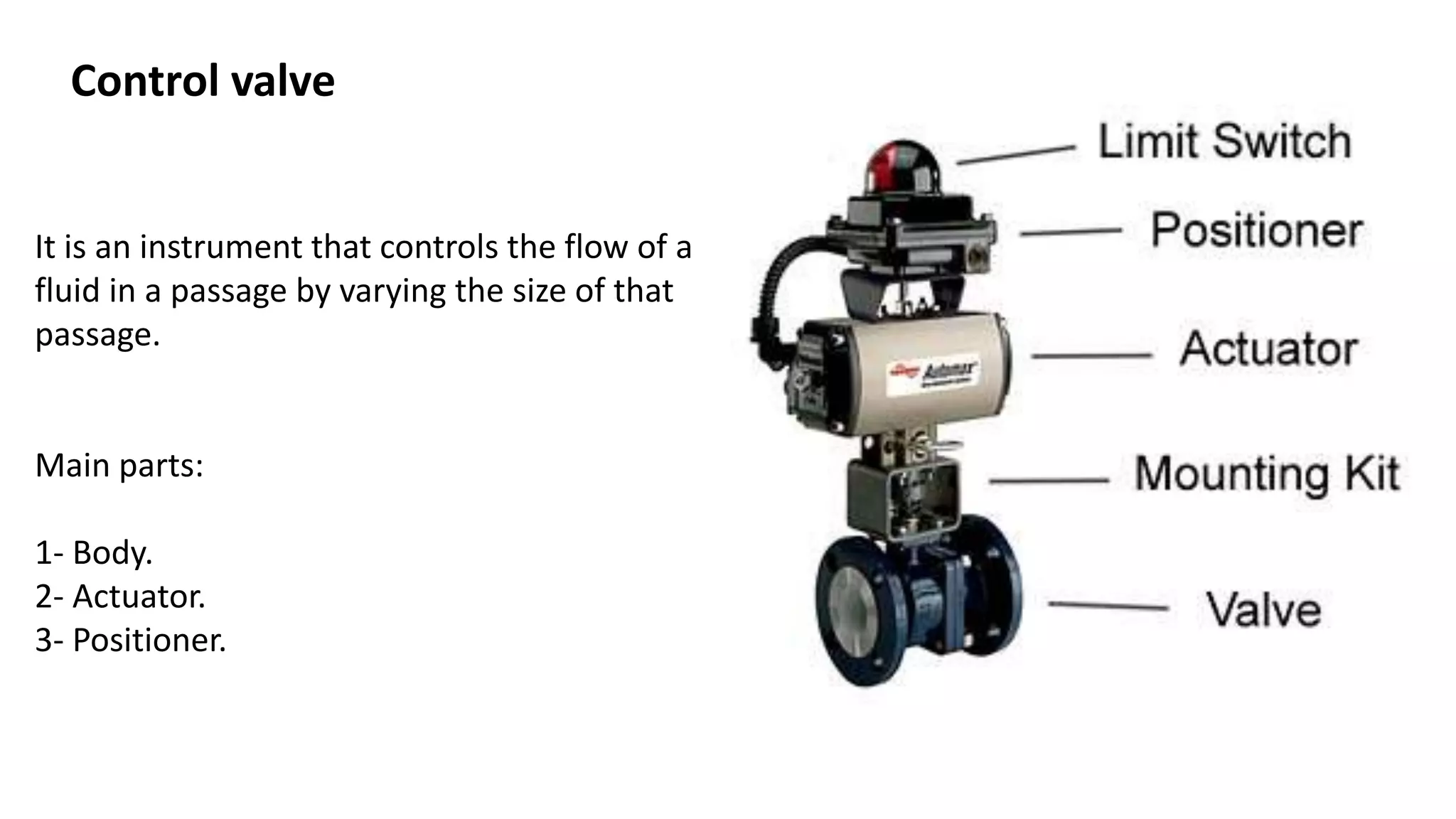
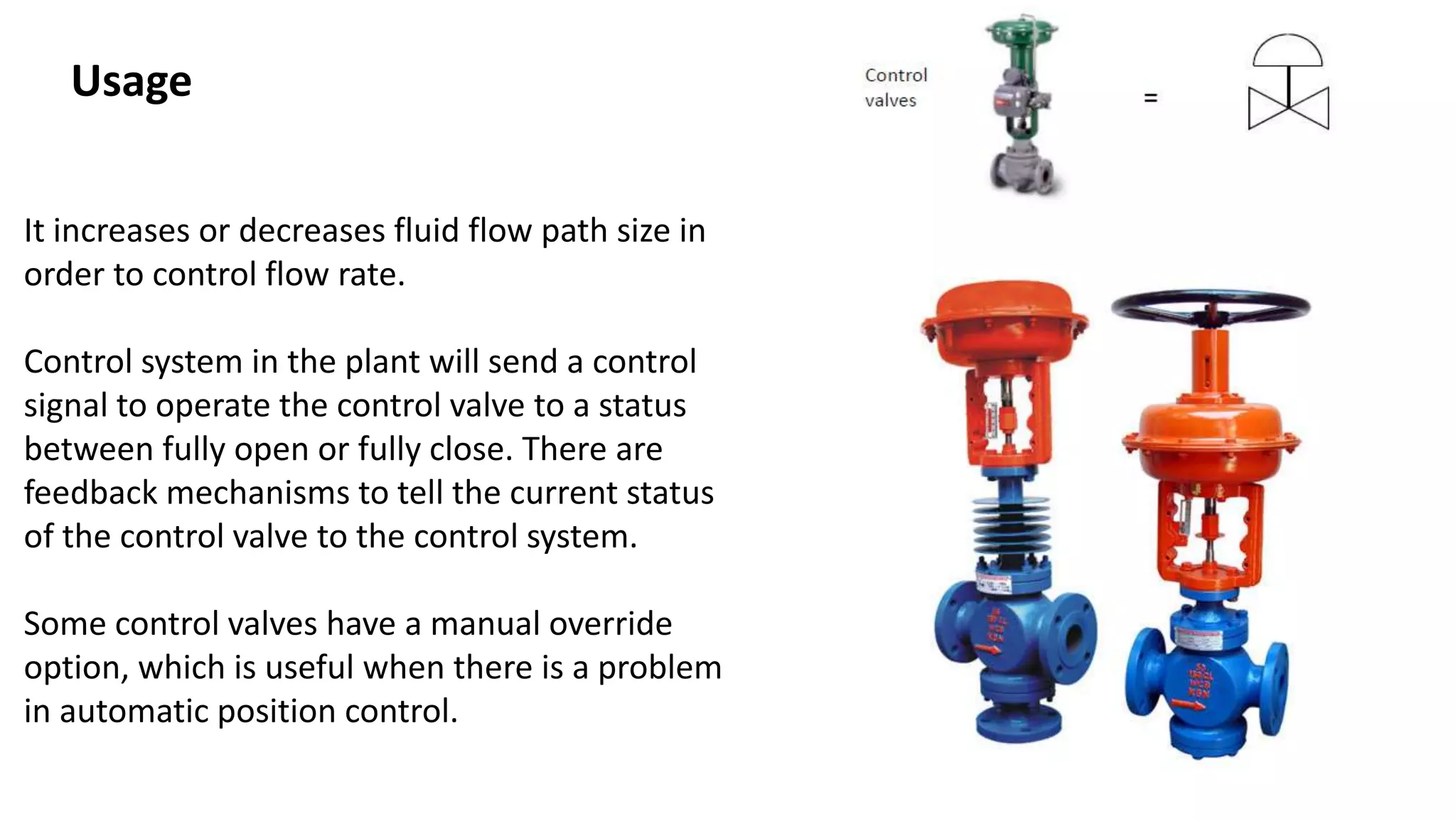
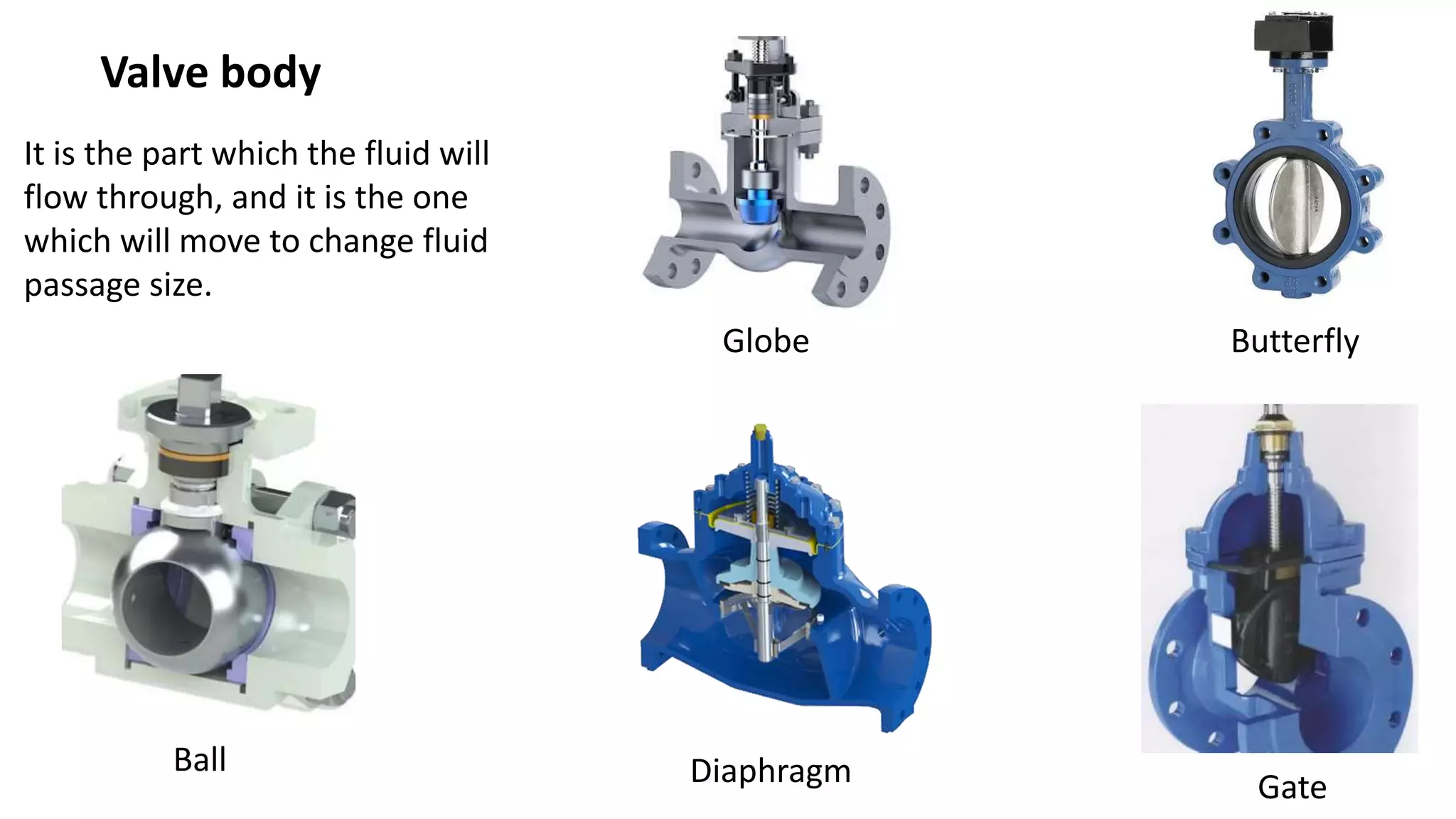
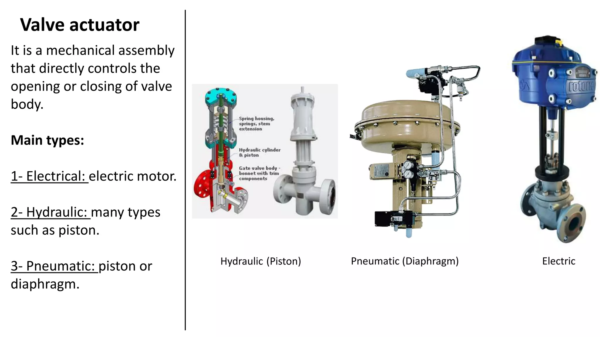
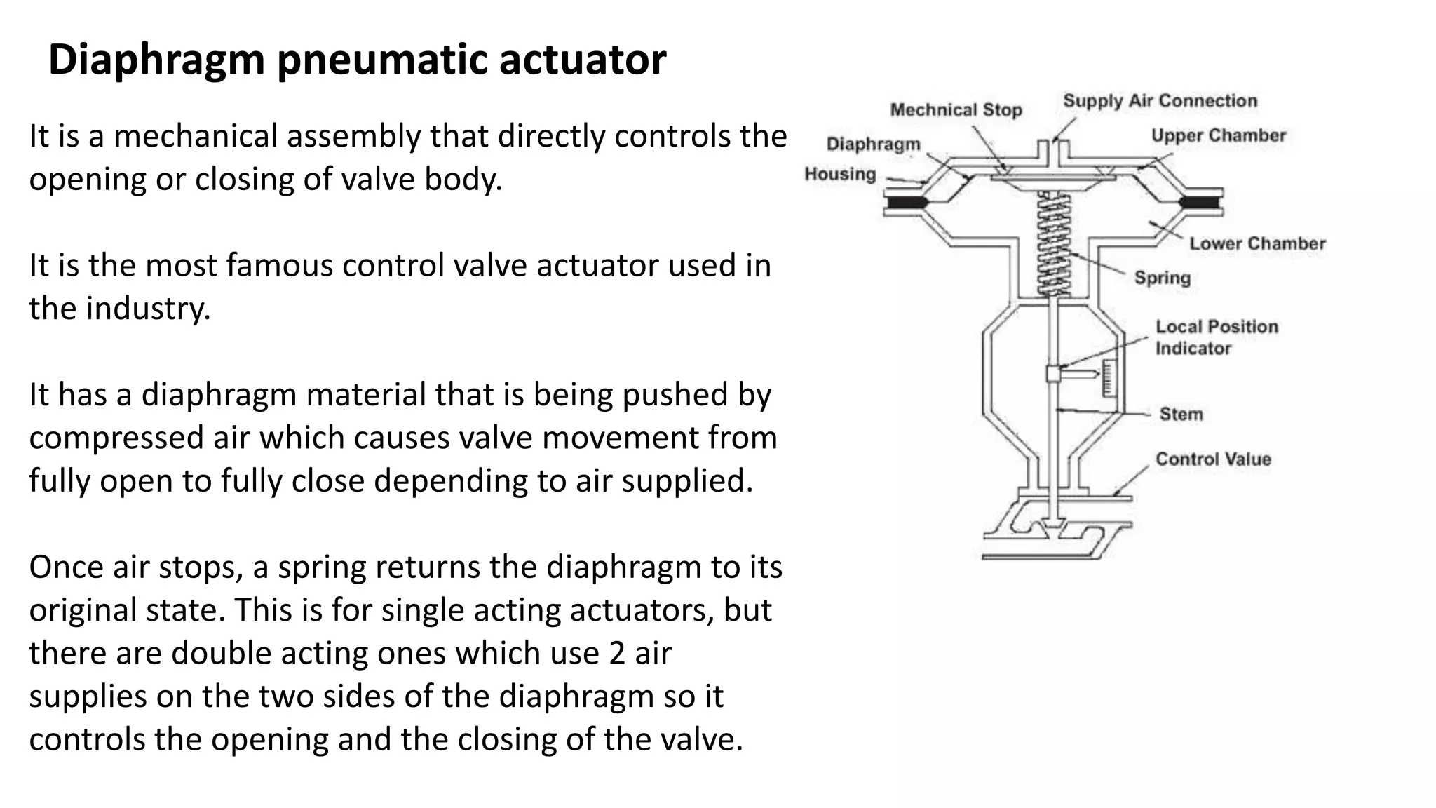
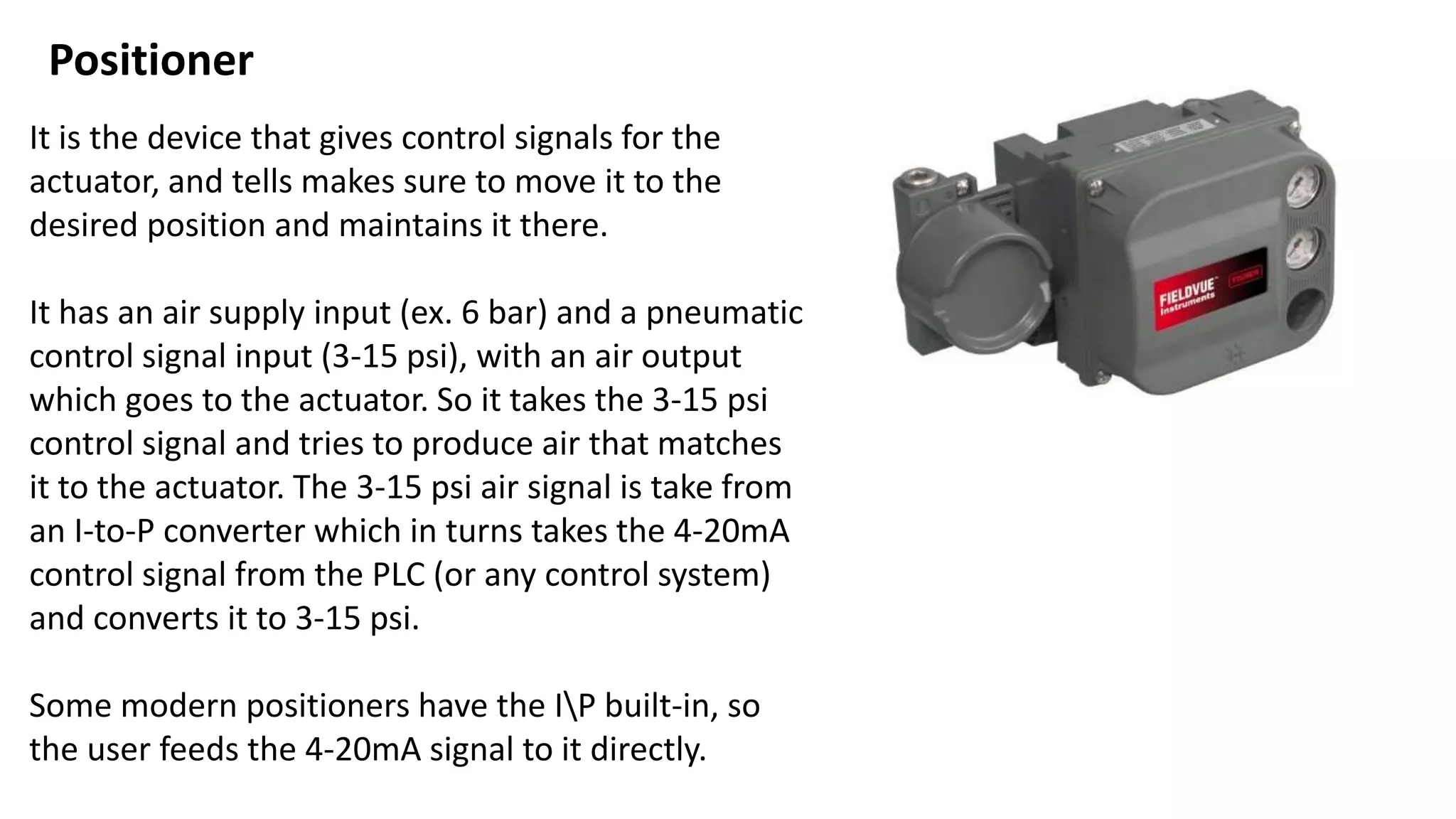
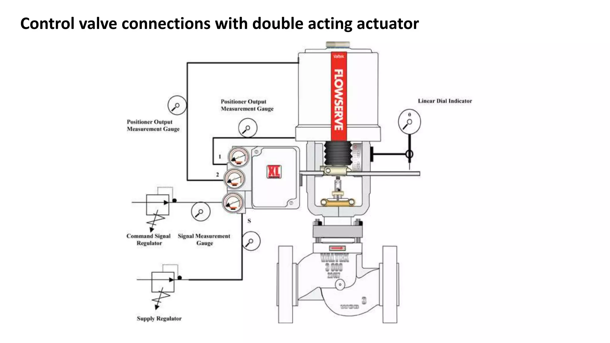
It is an instrument that controls the flow of a
fluid in a passage by varying the size of that
passage.
Main parts:
1- Body.
2- Actuator.
3- Positioner.
Control valve
It increases or decreases fluid flow path size in
order to control flow rate.
Control system in the plant will send a control
signal to operate the control valve to a status
between fully open or fully close. There are
feedback mechanisms to tell the current status
of the control valve to the control system.
Some control valves have a manual override
option, which is useful when there is a problem
in automatic position control.
Usage
It is the part which the fluid will
flow through, and it is the one
which will move to change fluid
passage size.
Valve body
Globe Butterfly
GateDiaphragmBall
It is a mechanical assembly
that directly controls the
opening or closing of valve
body.
Main types:
1- Electrical: electric motor.
2- Hydraulic: many types
such as piston.
3- Pneumatic: piston or
diaphragm.
Valve actuator
Hydraulic (Piston) Pneumatic (Diaphragm) Electric
It is a mechanical assembly that directly controls the
opening or closing of valve body.
It is the most famous control valve actuator used in
the industry.
It has a diaphragm material that is being pushed by
compressed air which causes valve movement from
fully open to fully close depending to air supplied.
Once air stops, a spring returns the diaphragm to its
original state. This is for single acting actuators, but
there are double acting ones which use 2 air
supplies on the two sides of the diaphragm so it
controls the opening and the closing of the valve.
Diaphragm pneumatic actuator
It is the device that gives control signals for the
actuator, and tells makes sure to move it to the
desired position and maintains it there.
It has an air supply input (ex. 6 bar) and a pneumatic
control signal input (3-15 psi), with an air output
which goes to the actuator. So it takes the 3-15 psi
control signal and tries to produce air that matches
it to the actuator. The 3-15 psi air signal is take from
an I-to-P converter which in turns takes the 4-20mA
control signal from the PLC (or any control system)
and converts it to 3-15 psi.
Some modern positioners have the IP built-in, so
the user feeds the 4-20mA signal to it directly.
Positioner
Control valve connections with double acting actuator

What is a control valve?

  • 2.
    It is aninstrument that controls the flow of a fluid in a passage by varying the size of that passage. Main parts: 1- Body. 2- Actuator. 3- Positioner. Control valve
  • 3.
    It increases ordecreases fluid flow path size in order to control flow rate. Control system in the plant will send a control signal to operate the control valve to a status between fully open or fully close. There are feedback mechanisms to tell the current status of the control valve to the control system. Some control valves have a manual override option, which is useful when there is a problem in automatic position control. Usage
  • 4.
    It is thepart which the fluid will flow through, and it is the one which will move to change fluid passage size. Valve body Globe Butterfly GateDiaphragmBall
  • 5.
    It is amechanical assembly that directly controls the opening or closing of valve body. Main types: 1- Electrical: electric motor. 2- Hydraulic: many types such as piston. 3- Pneumatic: piston or diaphragm. Valve actuator Hydraulic (Piston) Pneumatic (Diaphragm) Electric
  • 6.
    It is amechanical assembly that directly controls the opening or closing of valve body. It is the most famous control valve actuator used in the industry. It has a diaphragm material that is being pushed by compressed air which causes valve movement from fully open to fully close depending to air supplied. Once air stops, a spring returns the diaphragm to its original state. This is for single acting actuators, but there are double acting ones which use 2 air supplies on the two sides of the diaphragm so it controls the opening and the closing of the valve. Diaphragm pneumatic actuator
  • 7.
    It is thedevice that gives control signals for the actuator, and tells makes sure to move it to the desired position and maintains it there. It has an air supply input (ex. 6 bar) and a pneumatic control signal input (3-15 psi), with an air output which goes to the actuator. So it takes the 3-15 psi control signal and tries to produce air that matches it to the actuator. The 3-15 psi air signal is take from an I-to-P converter which in turns takes the 4-20mA control signal from the PLC (or any control system) and converts it to 3-15 psi. Some modern positioners have the IP built-in, so the user feeds the 4-20mA signal to it directly. Positioner
  • 8.
    Control valve connectionswith double acting actuator