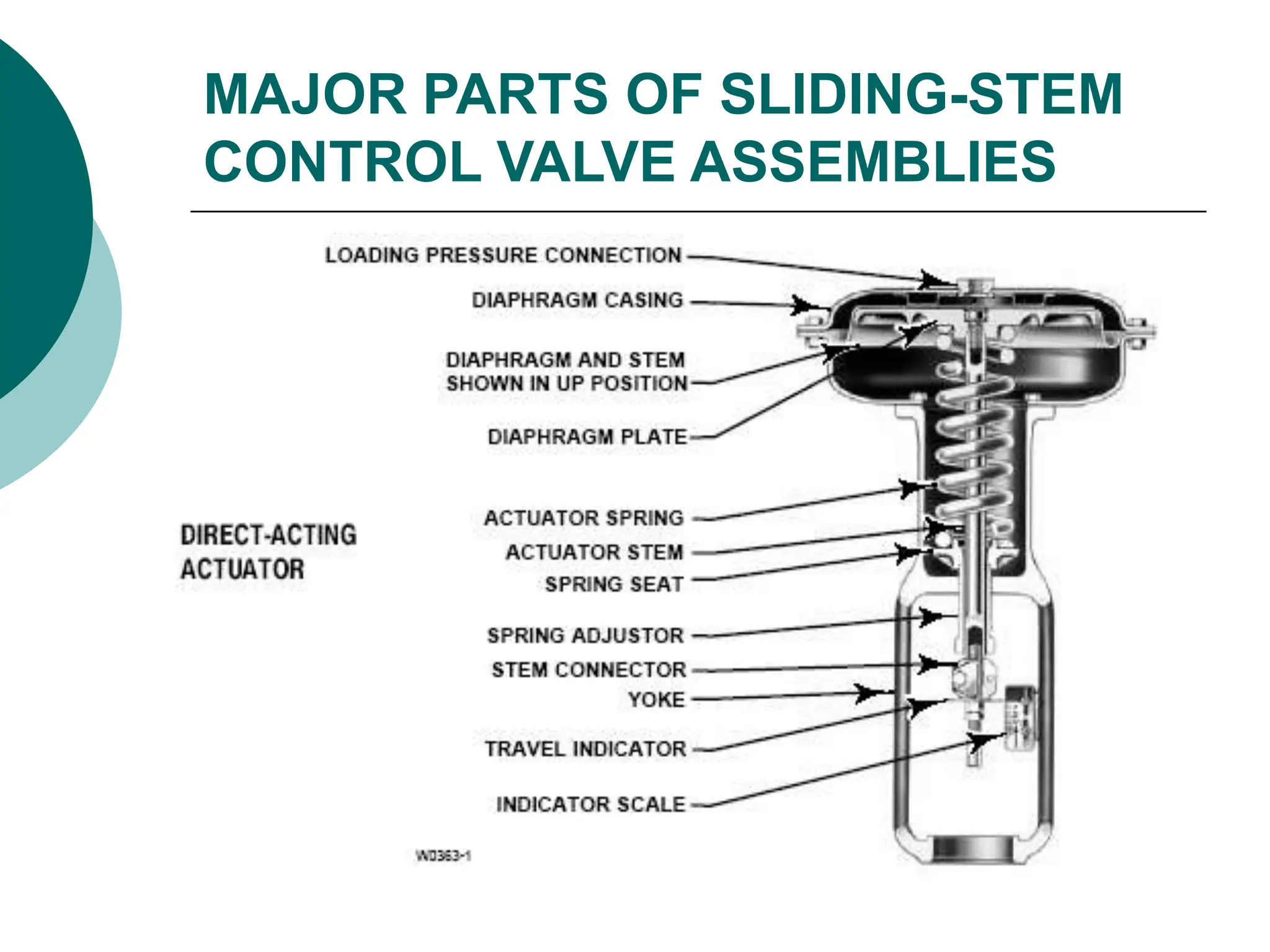
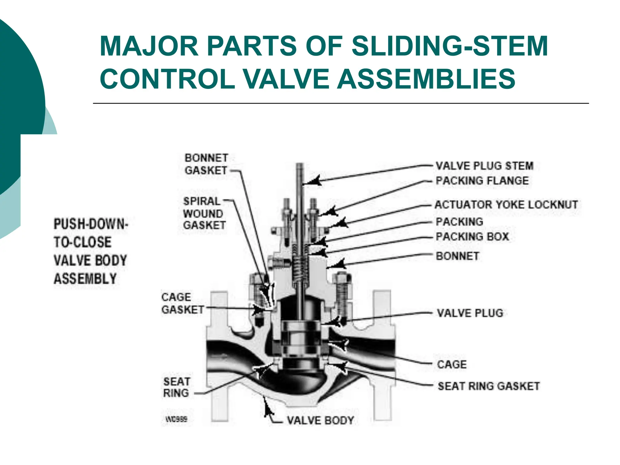
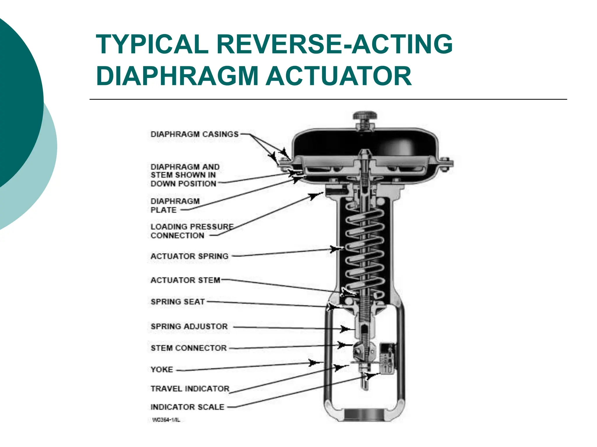
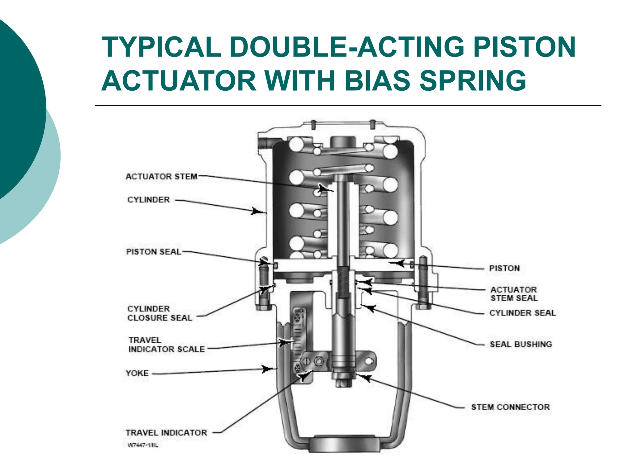
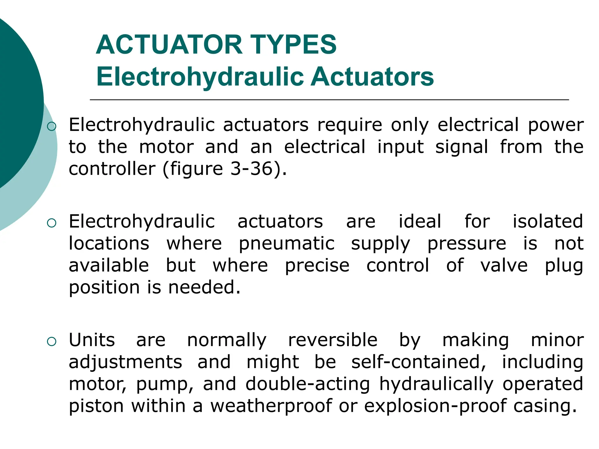
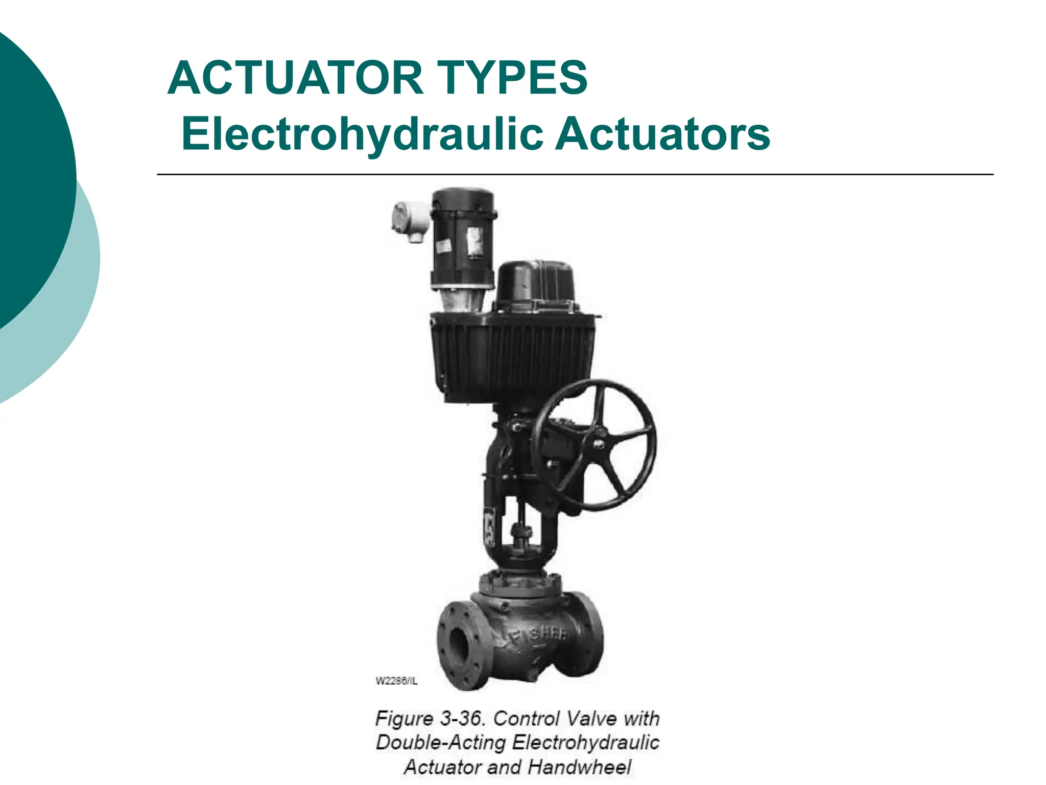
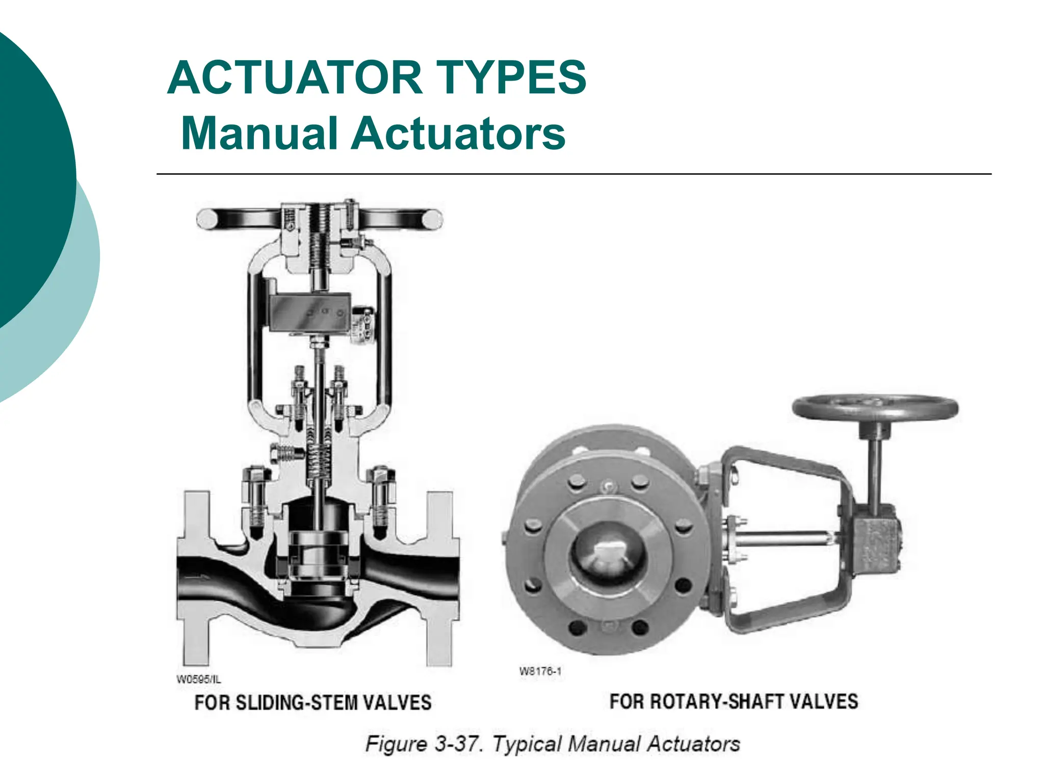
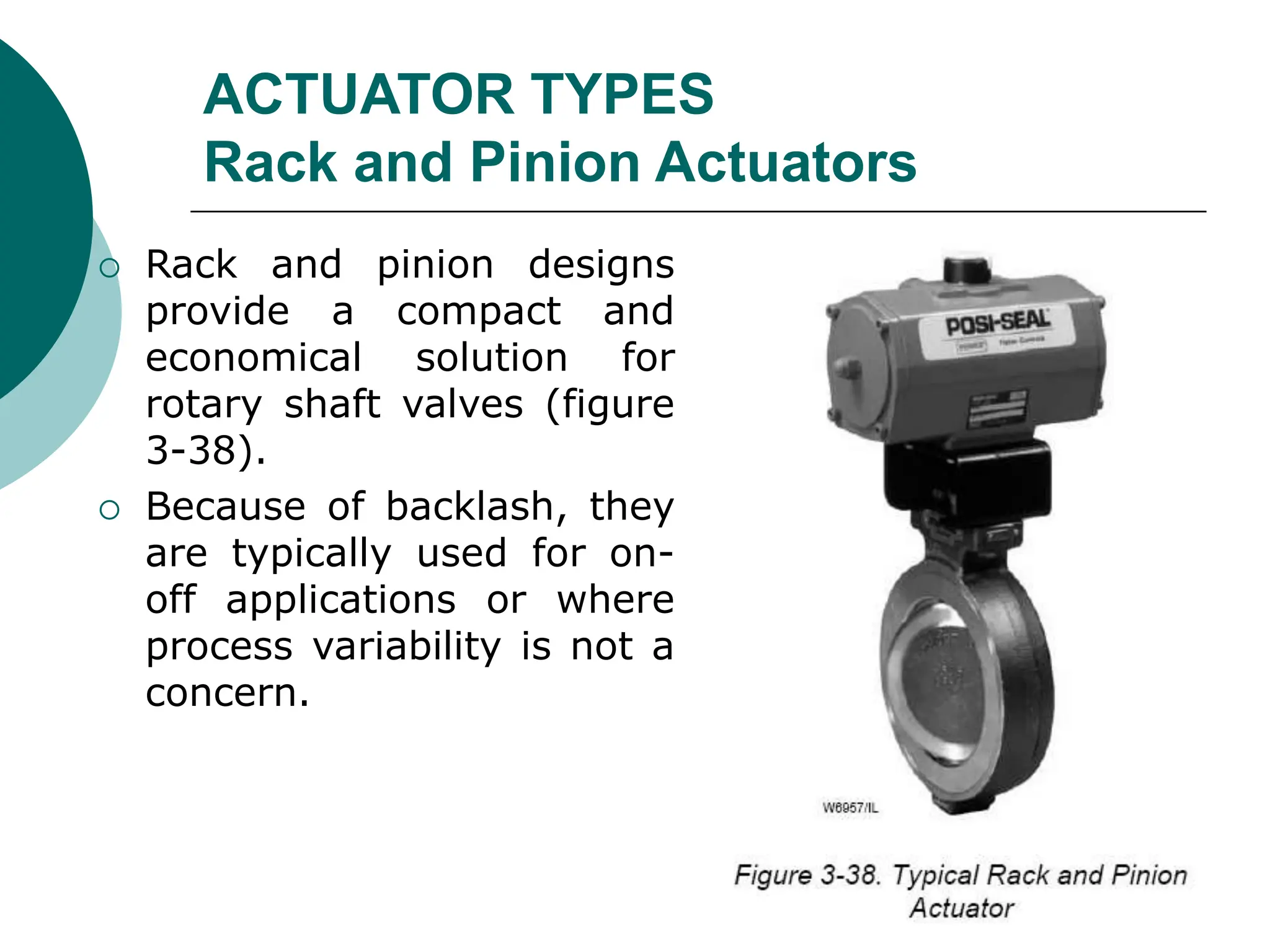
Lecture: 38
PNEUMATIC CONTROL VALVE
What Is A Control Valve?
 Process plants consist of hundreds, or even
thousands, of control loops all networked together
to produce a product to be offered for sale.
 Each of these control loops is designed to keep
some important process variable such as pressure,
flow, level, temperature, etc. within a required
operating range to ensure the quality of the end
product.
 Each of these loops receives and internally creates
disturbances that detrimentally affect the process
variable, and interaction from other loops in the
network provides disturbances that influence the
process variable.
BASICS OF CONTROL VALVE
 To reduce the effect of these load disturbances,
sensors and transmitters collect information about
the process variable and its relationship to some
desired set point.
 A controller then processes this information and
decides what must be done to get the process
variable back to where it should be after a load
disturbance occurs.
 When all the measuring, comparing, and calculating
are done, some type of final control element must
implement the strategy selected by the controller.
BASICS OF CONTROL VALVE
 The most common final control element in the
process control industries is the control valve.
 The control valve manipulates a flowing fluid, such
as gas, steam, water, or chemical compounds, to
compensate for the load disturbance and keep the
regulated process variable as close as possible to
the desired set point.
BASICS OF CONTROL VALVE
 Many people who talk about control valves or valves
are really referring to a control valve assembly.
 The control valve assembly typically consists of
 the valve body,
 the internal trim parts,
 an actuator to provide the motive power to operate
the valve,
 and a variety of additional valve accessories, which
 can include
 positioners, transducers, supply pressure regulators,
manual operators, snubbers, or limit switches.
BASICS OF CONTROL VALVE
 Accessory: A device that is mounted on the actuator to
complement the actuator’s function and make it a
complete operating unit. Examples include positioners,
supply pressure regulators, solenoids, and limit switches.
 Actuator: A pneumatic, hydraulic, or electrically
powered device that supplies force and motion to open or
close a valve.
 Actuator Assembly: An actuator, including all the
pertinent accessories that make it a complete operating
unit.
 Capacity: The rate of flow through a valve under stated
conditions.
 Dead Time: The time interval (Td) in which no response
of the system is detected following a small (usually
0.25% - 5%) step input.
TERMINOLOGY
 Disk: A valve trim element used to modulate the flow
rate with either linear or rotary motion. Can also be
referred to as a valve plug or closure member.
 Hysteresis: The maximum difference in output value for
any single input value during a calibration cycle,
excluding errors due to dead band.
 I/P: Shorthand for current-to-pressure (I-to-P). Typically
applied to input transducer modules.
 Linearity: The closeness to which a curve relating to two
variables approximates a straight line.
 Positioner: A position controller (servomechanism) that
is mechanically connected to a moving part of a final
control element or its actuator and that automatically
adjusts its output to the actuator to maintain a desired
position in proportion to the input signal.
TERMINOLOGY
 Relay: A device that acts as a power amplifier. It takes
an electrical, pneumatic, or mechanical input signal and
produces an output of a large volume flow of air or
hydraulic fluid to the actuator. The relay can be an
internal component of the positioner or a separate valve
accessory.
 Sensor: A device that senses the value of the process
variable and provides a corresponding output signal to a
transmitter. The sensor can be an integral part of the
transmitter, or it may be a separate component.
 Sizing (Valve): A systematic procedure designed to
ensure the correct valve capacity for a set of specified
process conditions.
For further refer
FISHER’S CONTROL VALVE HANDBOOK (4TH ED)
TERMINOLOGY
MAJOR PARTS OF SLIDING-STEM
CONTROL VALVE ASSEMBLIES
MAJOR PARTS OF SLIDING-STEM
CONTROL VALVE ASSEMBLIES
MAJOR PARTS OF SLIDING-STEM
CONTROL VALVE ASSEMBLIES
TYPICAL REVERSE-ACTING
DIAPHRAGM ACTUATOR
TYPICAL DOUBLE-ACTING PISTON
ACTUATOR WITH BIAS SPRING
CHARACTERIZED CAGES FOR
GLOBE-STYLE VALVE BODIES
 Cage: A part of a valve trim that surrounds the
closure member and can provide flow characterization
and/or a seating surface. It also provides stability,
guiding, balance, and alignment, and facilitates
assembly of other parts of the valve trim. The walls of
the cage contain openings that usually determine the
flow characteristic of the control valve.
OTHER STYLE VALVE BODIES
ROTARY-SHAFT CONTROL VALVES
ACTUATOR
 Pneumatically operated control valve actuators are the
most popular type in use, but electric, hydraulic, and
manual actuators are also widely used.
 The spring-and-diaphragm pneumatic actuator is most
commonly specified due to its dependability and
simplicity of design.
 Pneumatically operated piston actuators provide high
stem force output for demanding service conditions.
 Electric and electro-hydraulic actuators are more
complex and more expensive than pneumatic
actuators.
 They offer advantages where no air supply source is
available, where low ambient temperatures could
freeze condensed water in pneumatic supply lines, or
where unusually large stem forces are needed.
ACTUATOR TYPES
Diaphragm Actuator
ACTUATOR TYPES
Diaphragm Actuator
 Pneumatically operated diaphragm actuators use air
supply from controller, positioner, or other source.
 Various styles include:
 directacting (increasing air pressure pushes down
diaphragm and extends actuator stem);
 reverse-acting (increasing air pressure pushes up
diaphragm and retracts actuator stem);
 reversible (actuators that can be assembled for either
direct or reverse action);
 direct-acting unit for rotary valves (increasing air
pressure pushes down on diaphragm, which may
either open or close the valve, depending on
orientation of the actuator lever on the valve shaft,).
ACTUATOR TYPES
Diaphragm Actuator Characteristics
 Net output thrust is the difference between
diaphragm force and opposing spring force.
 Molded diaphragms provide linear
performance and increased travels.
 Output thrust required and supply air
pressure available dictate size.
 Diaphragm actuators are simple,
dependable, and economical.
ACTUATOR TYPES
Piston Actuator
o Piston actuators are pneumatically operated using high-
pressure plant air to 150 psig, often eliminating the
need for supply pressure regulator.
o Piston actuators furnish maximum thrust output and
fast stroking speeds.
o Piston actuators are double acting to give maximum
force in both directions, or spring return to provide fail-
open or fail-closed operation (figure 3-35).
o Various accessories can be incorporated to position a
double-acting piston in the event of supply pressure
failure. These include pneumatic trip valves and lock-up
systems.
o Also available are hydraulic snubbers, handwheels, and
units without yokes, which can be used to operate
butterfly valves, louvers, and similar industrial
ACTUATOR TYPES
Piston Actuator
ACTUATOR TYPES
Electrohydraulic Actuators
 Electrohydraulic actuators require only electrical power
to the motor and an electrical input signal from the
controller (figure 3-36).
 Electrohydraulic actuators are ideal for isolated
locations where pneumatic supply pressure is not
available but where precise control of valve plug
position is needed.
 Units are normally reversible by making minor
adjustments and might be self-contained, including
motor, pump, and double-acting hydraulically operated
piston within a weatherproof or explosion-proof casing.
ACTUATOR TYPES
Electrohydraulic Actuators
ACTUATOR TYPES
Manual Actuators
 Manual actuators are useful where automatic control is
not required, but where ease of operation and good
manual control is still necessary (figure 3-37).
 They are often used to actuate the bypass valve in a
three-valve bypass loop around control valves for
manual control of the process during maintenance or
shutdown of the automatic system.
 Manual actuators are available in various sizes for both
globe-style valves and rotary-shaft valves.
 Dial-indicating devices are available for some models to
permit accurate repositioning of the valve plug or disk.
 Manual actuators are much less expensive than
automatic actuators.
ACTUATOR TYPES
Manual Actuators
ACTUATOR TYPES
Rack and Pinion Actuators
 Rack and pinion designs
provide a compact and
economical solution for
rotary shaft valves (figure
3-38).
 Because of backlash, they
are typically used for on-
off applications or where
process variability is not a
concern.
ACTUATOR TYPES
Electric Actuators
 Traditional electric actuator designs use an electric
motor and some form of gear reduction to move the
valve.
 Through adaptation, these mechanisms have been
used for continuous control with varying degrees of
success.
 To date, electric actuators have been much more
expensive than pneumatic for the same performance
levels.
 This is an area of rapid technological change, and
future designs may cause a shift towards greater use
of electric actuators.
Introduction to Pneumatic Control Valves.ppt

Introduction to Pneumatic Control Valves.ppt

  • 1.
  • 2.
    What Is AControl Valve?  Process plants consist of hundreds, or even thousands, of control loops all networked together to produce a product to be offered for sale.  Each of these control loops is designed to keep some important process variable such as pressure, flow, level, temperature, etc. within a required operating range to ensure the quality of the end product.  Each of these loops receives and internally creates disturbances that detrimentally affect the process variable, and interaction from other loops in the network provides disturbances that influence the process variable. BASICS OF CONTROL VALVE
  • 3.
     To reducethe effect of these load disturbances, sensors and transmitters collect information about the process variable and its relationship to some desired set point.  A controller then processes this information and decides what must be done to get the process variable back to where it should be after a load disturbance occurs.  When all the measuring, comparing, and calculating are done, some type of final control element must implement the strategy selected by the controller. BASICS OF CONTROL VALVE
  • 4.
     The mostcommon final control element in the process control industries is the control valve.  The control valve manipulates a flowing fluid, such as gas, steam, water, or chemical compounds, to compensate for the load disturbance and keep the regulated process variable as close as possible to the desired set point. BASICS OF CONTROL VALVE
  • 5.
     Many peoplewho talk about control valves or valves are really referring to a control valve assembly.  The control valve assembly typically consists of  the valve body,  the internal trim parts,  an actuator to provide the motive power to operate the valve,  and a variety of additional valve accessories, which  can include  positioners, transducers, supply pressure regulators, manual operators, snubbers, or limit switches. BASICS OF CONTROL VALVE
  • 6.
     Accessory: Adevice that is mounted on the actuator to complement the actuator’s function and make it a complete operating unit. Examples include positioners, supply pressure regulators, solenoids, and limit switches.  Actuator: A pneumatic, hydraulic, or electrically powered device that supplies force and motion to open or close a valve.  Actuator Assembly: An actuator, including all the pertinent accessories that make it a complete operating unit.  Capacity: The rate of flow through a valve under stated conditions.  Dead Time: The time interval (Td) in which no response of the system is detected following a small (usually 0.25% - 5%) step input. TERMINOLOGY
  • 7.
     Disk: Avalve trim element used to modulate the flow rate with either linear or rotary motion. Can also be referred to as a valve plug or closure member.  Hysteresis: The maximum difference in output value for any single input value during a calibration cycle, excluding errors due to dead band.  I/P: Shorthand for current-to-pressure (I-to-P). Typically applied to input transducer modules.  Linearity: The closeness to which a curve relating to two variables approximates a straight line.  Positioner: A position controller (servomechanism) that is mechanically connected to a moving part of a final control element or its actuator and that automatically adjusts its output to the actuator to maintain a desired position in proportion to the input signal. TERMINOLOGY
  • 8.
     Relay: Adevice that acts as a power amplifier. It takes an electrical, pneumatic, or mechanical input signal and produces an output of a large volume flow of air or hydraulic fluid to the actuator. The relay can be an internal component of the positioner or a separate valve accessory.  Sensor: A device that senses the value of the process variable and provides a corresponding output signal to a transmitter. The sensor can be an integral part of the transmitter, or it may be a separate component.  Sizing (Valve): A systematic procedure designed to ensure the correct valve capacity for a set of specified process conditions. For further refer FISHER’S CONTROL VALVE HANDBOOK (4TH ED) TERMINOLOGY
  • 9.
    MAJOR PARTS OFSLIDING-STEM CONTROL VALVE ASSEMBLIES
  • 10.
    MAJOR PARTS OFSLIDING-STEM CONTROL VALVE ASSEMBLIES
  • 11.
    MAJOR PARTS OFSLIDING-STEM CONTROL VALVE ASSEMBLIES
  • 12.
  • 13.
  • 14.
    CHARACTERIZED CAGES FOR GLOBE-STYLEVALVE BODIES  Cage: A part of a valve trim that surrounds the closure member and can provide flow characterization and/or a seating surface. It also provides stability, guiding, balance, and alignment, and facilitates assembly of other parts of the valve trim. The walls of the cage contain openings that usually determine the flow characteristic of the control valve.
  • 15.
  • 16.
  • 17.
  • 18.
    ACTUATOR  Pneumatically operatedcontrol valve actuators are the most popular type in use, but electric, hydraulic, and manual actuators are also widely used.  The spring-and-diaphragm pneumatic actuator is most commonly specified due to its dependability and simplicity of design.  Pneumatically operated piston actuators provide high stem force output for demanding service conditions.  Electric and electro-hydraulic actuators are more complex and more expensive than pneumatic actuators.  They offer advantages where no air supply source is available, where low ambient temperatures could freeze condensed water in pneumatic supply lines, or where unusually large stem forces are needed.
  • 19.
  • 20.
    ACTUATOR TYPES Diaphragm Actuator Pneumatically operated diaphragm actuators use air supply from controller, positioner, or other source.  Various styles include:  directacting (increasing air pressure pushes down diaphragm and extends actuator stem);  reverse-acting (increasing air pressure pushes up diaphragm and retracts actuator stem);  reversible (actuators that can be assembled for either direct or reverse action);  direct-acting unit for rotary valves (increasing air pressure pushes down on diaphragm, which may either open or close the valve, depending on orientation of the actuator lever on the valve shaft,).
  • 21.
    ACTUATOR TYPES Diaphragm ActuatorCharacteristics  Net output thrust is the difference between diaphragm force and opposing spring force.  Molded diaphragms provide linear performance and increased travels.  Output thrust required and supply air pressure available dictate size.  Diaphragm actuators are simple, dependable, and economical.
  • 22.
    ACTUATOR TYPES Piston Actuator oPiston actuators are pneumatically operated using high- pressure plant air to 150 psig, often eliminating the need for supply pressure regulator. o Piston actuators furnish maximum thrust output and fast stroking speeds. o Piston actuators are double acting to give maximum force in both directions, or spring return to provide fail- open or fail-closed operation (figure 3-35). o Various accessories can be incorporated to position a double-acting piston in the event of supply pressure failure. These include pneumatic trip valves and lock-up systems. o Also available are hydraulic snubbers, handwheels, and units without yokes, which can be used to operate butterfly valves, louvers, and similar industrial
  • 23.
  • 24.
    ACTUATOR TYPES Electrohydraulic Actuators Electrohydraulic actuators require only electrical power to the motor and an electrical input signal from the controller (figure 3-36).  Electrohydraulic actuators are ideal for isolated locations where pneumatic supply pressure is not available but where precise control of valve plug position is needed.  Units are normally reversible by making minor adjustments and might be self-contained, including motor, pump, and double-acting hydraulically operated piston within a weatherproof or explosion-proof casing.
  • 25.
  • 26.
    ACTUATOR TYPES Manual Actuators Manual actuators are useful where automatic control is not required, but where ease of operation and good manual control is still necessary (figure 3-37).  They are often used to actuate the bypass valve in a three-valve bypass loop around control valves for manual control of the process during maintenance or shutdown of the automatic system.  Manual actuators are available in various sizes for both globe-style valves and rotary-shaft valves.  Dial-indicating devices are available for some models to permit accurate repositioning of the valve plug or disk.  Manual actuators are much less expensive than automatic actuators.
  • 27.
  • 28.
    ACTUATOR TYPES Rack andPinion Actuators  Rack and pinion designs provide a compact and economical solution for rotary shaft valves (figure 3-38).  Because of backlash, they are typically used for on- off applications or where process variability is not a concern.
  • 29.
    ACTUATOR TYPES Electric Actuators Traditional electric actuator designs use an electric motor and some form of gear reduction to move the valve.  Through adaptation, these mechanisms have been used for continuous control with varying degrees of success.  To date, electric actuators have been much more expensive than pneumatic for the same performance levels.  This is an area of rapid technological change, and future designs may cause a shift towards greater use of electric actuators.