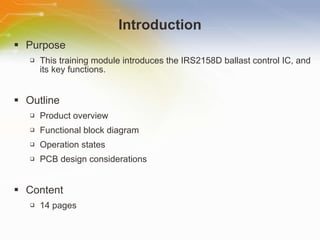
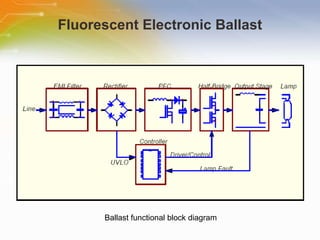
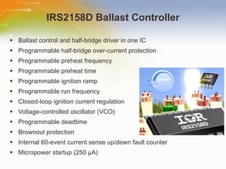
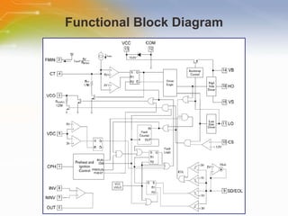
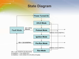
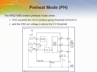
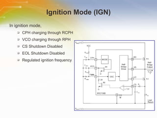
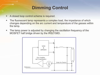
Control ICs for Energy-efficient Fluorescent Ballast Applications  Source: International Rectifier
Introduction Purpose This training module introduces the IRS2158D ballast control IC, and its key functions. Outline Product overview Functional block diagram Operation states PCB design considerations Content 14 pages
Fluorescent Electronic Ballast Ballast functional block diagram
IRS2158D Ballast Controller Ballast control and half-bridge driver in one IC Programmable half-bridge over-current protection Programmable preheat frequency Programmable preheat time Programmable ignition ramp Programmable run frequency Closed-loop ignition current regulation Voltage-controlled oscillator (VCO) Programmable deadtime Brownout protection Internal 60-event current sense up/down fault counter Micropower startup (250 μA)
Functional Block Diagram
State Diagram Power Turned On UVLO Mode Preheat Mode Ignition Mode Pre-Run Mode Run Mode Fault Mode CS > 1.2V for 60events CS > 1.2V (VCSTH+) CS > 1.2V (VCSTH+) for 60 events Or SD/EOL < 1.0V (VEOLTH-) Or SD/EOL > 3.0V (VEOLTH+) For 60 LO Cycles SD/EOL>5.0V (VSDTH+) SD/EOL>5.0V (VSDTH+)
Under-voltage Lock-Out Mode (UVLO) Mode During the UVLO mode, Half-bridge is off IQCCUV: 250 µA CPH = 0V VCO = 0V (Oscillator off) The IC turns on and LO begins to oscillate, when the voltage at VCC exceeds the IC start-up threshold (VCCUV+) and the VDC pin is above 5 V and the SD pin is below 3 V
Preheat Mode (PH) The IRS2158D enters preheat mode when VCC exceeds the UVLO positive-going threshold (VCCUV+) and the VDC pin voltage is above the 5 V threshold
Ignition Mode (IGN) In ignition mode, CPH charging through RCPH VCO charging through RPH CS Shutdown Disabled EOL Shutdown Disabled Regulated ignition frequency
Pre-Run and Run Mode In pre-run mode, CPH charging through RCPH VCO charging through RPH frequency ramps to f RUN CS One Fault Enabled EOL Shutdown Disabled In run mode, VCO= 5V Half-Bridge Oscillating @ f RUN CS Fault Counter Enabled EOL Thresholds Enabled
Dimming Control A closed loop control scheme is required. The fluorescent lamp represents a complex load, the impedance of which changes depending on the arc current and temperature of the gasses within the lamp. The lamp power is adjusted by changing the oscillation frequency of the MOSFET half bridge driven by the IRS2158D.
Protection Functions Lamp removal protection when a lamp is removed the ballast shuts down and when the lamp is replaced with a good one the ballast starts up again. End of Life protection It monitors the lamp voltage through the SD pin. Therefore the ballast will operate as long as the SD pin remains below 5 V. Brown-out If power to the ballast is shut off, the voltage on the VDC pin will drop below the VDC threshold, and shut the oscillator off. Thereby protecting the power transistors from potentially hazardous hard switching.
PCB Layout Considerations The signal ground (pin 12) should only be connected to the power ground at one single point to prevent ground loops from forming. The point described in (1) should be where the grounds of the current sense resistors for both the half bridge MOSFETs and the lamp current feedback both meet. The VCC decoupling capacitor should be placed as close to the IRS2158D VCC (pin 13) and COM (pin 12) as possible with the shortest possible traces. The devices, CPH, RFMIN, CVCO, CT and CCS should all be located as close to the IRS2158D as possible with traces to the relevant pins being as short as possible. The ground connections from the devices listed in (4) should be connected back to the COM pin of the IRS2158D through the shortest possible traces.  The charge pump diode connection to ground should be made to the power ground not the signal ground. The power factor correction section (if used) should be kept apart from the ballast control.
Additional Resource For ordering the IRS2158D, please click the part list or Call our sales hotline For additional inquires contact our technical service hotline For more product information go to https://ec.irf.com/v6/en/US/adirect/ir?cmd=catSearchFrame&domSendTo=byID&domProductQueryName=IRS2158DSPBF Newark Farnell

Control ICs for Energy-efficient Fluorescent Ballast Applications

  • 1.
    Control ICs forEnergy-efficient Fluorescent Ballast Applications Source: International Rectifier
  • 2.
    Introduction Purpose Thistraining module introduces the IRS2158D ballast control IC, and its key functions. Outline Product overview Functional block diagram Operation states PCB design considerations Content 14 pages
  • 3.
    Fluorescent Electronic BallastBallast functional block diagram
  • 4.
    IRS2158D Ballast ControllerBallast control and half-bridge driver in one IC Programmable half-bridge over-current protection Programmable preheat frequency Programmable preheat time Programmable ignition ramp Programmable run frequency Closed-loop ignition current regulation Voltage-controlled oscillator (VCO) Programmable deadtime Brownout protection Internal 60-event current sense up/down fault counter Micropower startup (250 μA)
  • 5.
  • 6.
    State Diagram PowerTurned On UVLO Mode Preheat Mode Ignition Mode Pre-Run Mode Run Mode Fault Mode CS > 1.2V for 60events CS > 1.2V (VCSTH+) CS > 1.2V (VCSTH+) for 60 events Or SD/EOL < 1.0V (VEOLTH-) Or SD/EOL > 3.0V (VEOLTH+) For 60 LO Cycles SD/EOL>5.0V (VSDTH+) SD/EOL>5.0V (VSDTH+)
  • 7.
    Under-voltage Lock-Out Mode(UVLO) Mode During the UVLO mode, Half-bridge is off IQCCUV: 250 µA CPH = 0V VCO = 0V (Oscillator off) The IC turns on and LO begins to oscillate, when the voltage at VCC exceeds the IC start-up threshold (VCCUV+) and the VDC pin is above 5 V and the SD pin is below 3 V
  • 8.
    Preheat Mode (PH)The IRS2158D enters preheat mode when VCC exceeds the UVLO positive-going threshold (VCCUV+) and the VDC pin voltage is above the 5 V threshold
  • 9.
    Ignition Mode (IGN)In ignition mode, CPH charging through RCPH VCO charging through RPH CS Shutdown Disabled EOL Shutdown Disabled Regulated ignition frequency
  • 10.
    Pre-Run and RunMode In pre-run mode, CPH charging through RCPH VCO charging through RPH frequency ramps to f RUN CS One Fault Enabled EOL Shutdown Disabled In run mode, VCO= 5V Half-Bridge Oscillating @ f RUN CS Fault Counter Enabled EOL Thresholds Enabled
  • 11.
    Dimming Control Aclosed loop control scheme is required. The fluorescent lamp represents a complex load, the impedance of which changes depending on the arc current and temperature of the gasses within the lamp. The lamp power is adjusted by changing the oscillation frequency of the MOSFET half bridge driven by the IRS2158D.
  • 12.
    Protection Functions Lampremoval protection when a lamp is removed the ballast shuts down and when the lamp is replaced with a good one the ballast starts up again. End of Life protection It monitors the lamp voltage through the SD pin. Therefore the ballast will operate as long as the SD pin remains below 5 V. Brown-out If power to the ballast is shut off, the voltage on the VDC pin will drop below the VDC threshold, and shut the oscillator off. Thereby protecting the power transistors from potentially hazardous hard switching.
  • 13.
    PCB Layout ConsiderationsThe signal ground (pin 12) should only be connected to the power ground at one single point to prevent ground loops from forming. The point described in (1) should be where the grounds of the current sense resistors for both the half bridge MOSFETs and the lamp current feedback both meet. The VCC decoupling capacitor should be placed as close to the IRS2158D VCC (pin 13) and COM (pin 12) as possible with the shortest possible traces. The devices, CPH, RFMIN, CVCO, CT and CCS should all be located as close to the IRS2158D as possible with traces to the relevant pins being as short as possible. The ground connections from the devices listed in (4) should be connected back to the COM pin of the IRS2158D through the shortest possible traces. The charge pump diode connection to ground should be made to the power ground not the signal ground. The power factor correction section (if used) should be kept apart from the ballast control.
  • 14.
    Additional Resource Forordering the IRS2158D, please click the part list or Call our sales hotline For additional inquires contact our technical service hotline For more product information go to https://ec.irf.com/v6/en/US/adirect/ir?cmd=catSearchFrame&domSendTo=byID&domProductQueryName=IRS2158DSPBF Newark Farnell

Editor's Notes

  • #2 Welcome to this training module on International Rectifier’s Control ICs for Energy-efficient Fluorescent Ballast Applications.
  • #3 This training module introduces the IRS2158D ballast control IC, its key functions and some design considerations.
  • #4 Fluorescent lamps are popular due to their low profile and high lumen/watt output. These lamps require a current for a specified time to preheat the filaments, and a high-voltage for ignition, and running power. The functions performed by present day fluorescent electronic ballasts include electromagnetic interference (EMI) filtering to block ballast generated noise, rectification, power factor correction (PFC) for sinusoidal input current, undervoltage lockout (UVLO) and fault protection, half-bridge switches with driver and timing for high-frequency operation, and final output stage to power the lamp.
  • #5 The IRS2158D is a fully integrated, fully protected 600V ballast control IC designed to drive all types of fluorescent lamps. It is a linear dimming ballast control IC with half-bridge driver in a compact 8-pin form factor. The device provides a competitive solution to replace inefficient incandescent bulbs in multi-level and three-way compact fluorescent lighting (CFL) applications. Requiring only small external components, the IRS2158D significantly simplifies and shrinks circuit design and delivers a dimming system performance of up to 10 percent for compact fluorescent lamps as well as linear ballasts. The device’s features are listed here.
  • #6 Here is the functional block diagram of the IRS2158D.
  • #7 This illustrates the state diagram of the IRS2158D. Under different conditions, the control IC goes to different modes, including under-voltage lock-out (UVLO) mode, preheat mode, ignition mode, pre-run mode, run mode, and fault mode.
  • #8 The under-voltage lock-out mode (UVLO) is defined as the state the IC is in when VCC is below the turn-on threshold of the IC. The IRS2158D undervoltage lock-out is designed to maintain an ultra low supply current of less than 500 μA, and to guarantee the IC is fully functional before the high- and low-side output drivers are activated. When the voltage at VCC exceeds the IC start-up threshold (VCCUV+) and the VDC pin is above 5volts and the Shut Down (SD) pin is below 3 V, the IC turns on and the Low side output (LO) begins to oscillate.
  • #9 The IRS2158D enters preheat mode when VCC exceeds the UVLO positive-going threshold (VCCUV+) and the VDC pin voltage is above the 5 V threshold. The internal MOSFET that connects pin CPH to COM is turned off and an external resistor begins to charge the external preheat timing capacitor (CPH). The low side output and High Side Output begin to oscillate at a higher soft-start frequency and ramp down quickly to the preheat frequency. The VCO pin is connected to COM through an internal MOSFET so the preheat frequency is determined by the equivalent resistance at the pin labeled Fmin, formed by the parallel combination of resistors RMIN and RPH. The frequency remains at the preheat frequency until the voltage on pin CPH exceeds 2/3*VCC (VCPHEOP) and the IC enters Ignition Mode.
  • #10 The IRS2158D ignition mode is defined by the second time CPH charges from 1/3*VCC (VCPHSOI-) to 1/2*VCC (VCHPRUN). When the voltage on pin CPH exceeds 2/3*VCC (VCPHEOP) for the first time, pin CPH is discharged quickly through an internal MOSFET down to 1/3*VCC (VCPHSOI-). The internal MOSFET turns off and the voltage on pin CPH begins to increase again. The operating frequency ramps down smoothly from the preheat frequency through the ignition frequency to the final run frequency. The IRS2158D remains in IGNITION mode until the voltage at CPH reaches 1/2*VCC at which point it will switch into PRE-RUN mode.
  • #11 In PRE-RUN mode the fault counter is disables so that the IRS2158D will enter FAULT mode if a single event occurs where VCS&gt;1.2 V (VCSTH+). This allows the ballast to shut down if the resonant inductor saturates during ignition. When CPH exceeds 2/3*VCC (VCPHRUN+) for the second time, the IC enters run mode and the fault counter becomes enabled. CPH continues to charge up to VCC. The operating frequency is at the minimum frequency and is programmed by the external resistor (RMIN) at the FMIN pin. During run mode, the end-of-life (EOL) window comparator and the DC bus under-voltage reset are both enabled.
  • #12 The design of dimmable ballast for linear lamps requires that the lamp power can be reduced smoothly to a low output level, less than 5% of nominal lumen output. It is necessary that the lamp output is able to be held at any level and that there will be no discernable flicker or instability at any level. The fluorescent lamp represents a complex load, the impedance of which changes depending on the arc current and temperature of the gasses within the lamp. In the dimming control design, the ballast supplies the lamp through a resonant output circuit. The lamp power is adjusted by changing the oscillation frequency of the MOSFET half bridge, which is driven by the IRS2158D. The VCO within the IRS2158D is driven by the output of an error amplifier and compensation network that senses the lamp arc current directly and compares it with a reference.
  • #13 The SD pin of the IRS2158D is used for lamp removal protection. If there is no lamp present the voltage at SD pin will be pulled above the 5 V threshold. When a lamp is removed the ballast shuts down, and when the lamp is replaced with a good one the ballast starts up again. During preheat and ignition modes the end of life protection function, which monitors the lamp voltage through the SD pin is not enabled, therefore the ballast will operate as long as the SD pin remains below 5 V. The devices provides brown out protection for the ballast which works by sensing the rectified AC line voltage at the positive output of BR1. When the VDC voltage falls below 3 V the IRS2158D shuts down. Without the brownout protection provided by the VDC pin, if a brownout did occur the ballast would shut down preventing the event of any hard switching.
  • #14 In order to successfully utilize the IRS2158D in a ballast design, it is necessary to follow the PCB layout guidelines as shown. These guidelines can help avoid possible interference and ground loop issues that can occur in the ballast circuit. These guideline also prevent high current ground loops from interfering with sensitive timing component operation, and allow the entire control circuit to reject common-mode noise due to output switching.
  • #15 Thank you for taking the time to view this presentation on “ Control ICs for Energy-efficient Fluorescent Ballast Applications” . If you would like to learn more or go on to purchase some of these devices, you may either click on the part list link, or simply call our sales hotline. For more technical information you may either visit the International Rectifier site – link shown – or if you would prefer to speak to someone live, please call our hotline number, or you could use our ‘live chat’ online facility.