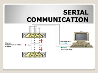
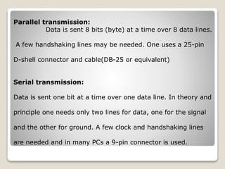
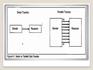
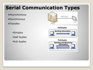
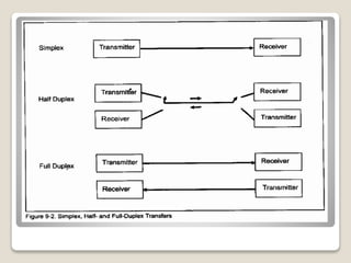
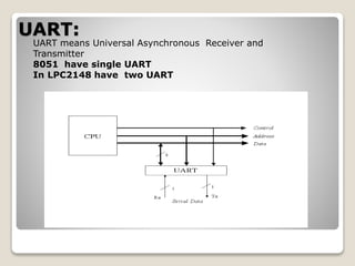
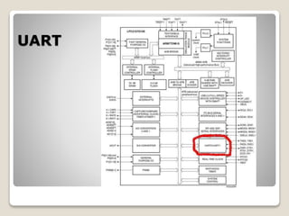
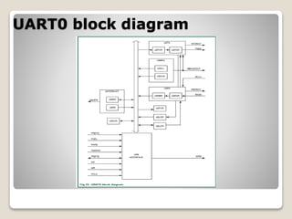
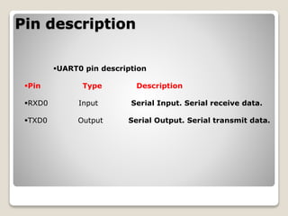
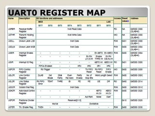
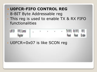
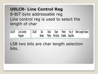
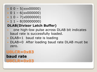
SERIAL
COMMUNICATION
Parallel transmission:
Data is sent 8 bits (byte) at a time over 8 data lines.
A few handshaking lines may be needed. One uses a 25-pin
D-shell connector and cable(DB-25 or equivalent)
Serial transmission:
Data is sent one bit at a time over one data line. In theory and
principle one needs only two lines for data, one for the signal
and the other for ground. A few clock and handshaking lines
are needed and in many PCs a 9-pin connector is used.
Serial Communication Types
Asynchronous
Synchronous
Transfer:
Simplex
Half duplex
Full duplex
Asynchronous Data
Synchronous Data
UART:
UART means Universal Asynchronous Receiver and
Transmitter
8051 have single UART
In LPC2148 have two UART
Serial communication in LPC2148
UART
UART0 block diagram
Pin description
UART0 pin description
Pin Type Description
RXD0 Input Serial Input. Serial receive data.
TXD0 Output Serial Output. Serial transmit data.
UART0 REGISTER MAP
 U0FCR-FIFO CONTROL REG
• 8-BIT Byte Addressable reg
• This reg is used to enable TX & RX FIFO
functionalities
• U0FCR=0x07 is like SCON reg
 U0LCR- Line Control Reg
• 8-BIT byte addressable reg
• Line control reg is used to select the
length of char
• LSB two bits are char length selection
bits.
U0LCR=0x83
baud rate
U0CLR=0x03
 0 0 – 5(xxx00000)
 0 1 – 6(xx000000)
 1 0 – 7(x0000000)
 1 1 – 8(00000000)
DLAB(Divisor Latch Buffer)
 one high-low pulse across DLAB bit indicates
baud rate is successfully loaded.
 DLAB=1 baud rate is loading
 DLAB=0 After loading baud rate DLAB must be
zero.
Baud rate=clk/16*9600
 Divisor Latch Reg
• DLR is 16-bit reg
• Used to load baud rate
• As the baud rate is 8-bit value, divide DLR
into two parts
• DLM & DLL(8-bit each)
• For 9600 baud rate
• U0DLL=0x63(12mhz)
• U0DLM=0x00
 U0THR(Transmit hold reg)
• 8-bit byte addressable reg
• Data can be loading to U0THR, whenever
transmitting data
• U0THR=‘A’----like SBUF
• THR buffer reg is used only for
transmitting
 U0RBR(UART0 Receive buffer reg)
 8-bit byte addressable reg
 Data can be loading into U0RBR,
whenever receiving data.
 a=U0RBR----like SBUF
 U0LSR(UART0 line status reg)
 8-bit byte addressable reg
 Consists of diff flag bits… TI interrupt & RI
interrupt flag bit
 0th bit of LSR is RI flag bit
 6th bit of LSR is TI flag bit
 Monitoring TI bit syntax
 While(!(U0LSR&0x40));
 Monitoring RI bit syntax
 While(!(U0LSR&0x10));
Serial communication in LPC2148

Serial communication in LPC2148

  • 1.
  • 2.
    Parallel transmission: Data issent 8 bits (byte) at a time over 8 data lines. A few handshaking lines may be needed. One uses a 25-pin D-shell connector and cable(DB-25 or equivalent) Serial transmission: Data is sent one bit at a time over one data line. In theory and principle one needs only two lines for data, one for the signal and the other for ground. A few clock and handshaking lines are needed and in many PCs a 9-pin connector is used.
  • 4.
  • 6.
  • 7.
    UART: UART means UniversalAsynchronous Receiver and Transmitter 8051 have single UART In LPC2148 have two UART
  • 8.
  • 9.
  • 10.
  • 11.
    Pin description UART0 pindescription Pin Type Description RXD0 Input Serial Input. Serial receive data. TXD0 Output Serial Output. Serial transmit data.
  • 12.
  • 13.
     U0FCR-FIFO CONTROLREG • 8-BIT Byte Addressable reg • This reg is used to enable TX & RX FIFO functionalities • U0FCR=0x07 is like SCON reg
  • 14.
     U0LCR- LineControl Reg • 8-BIT byte addressable reg • Line control reg is used to select the length of char • LSB two bits are char length selection bits.
  • 15.
    U0LCR=0x83 baud rate U0CLR=0x03  00 – 5(xxx00000)  0 1 – 6(xx000000)  1 0 – 7(x0000000)  1 1 – 8(00000000) DLAB(Divisor Latch Buffer)  one high-low pulse across DLAB bit indicates baud rate is successfully loaded.  DLAB=1 baud rate is loading  DLAB=0 After loading baud rate DLAB must be zero.
  • 16.
    Baud rate=clk/16*9600  DivisorLatch Reg • DLR is 16-bit reg • Used to load baud rate • As the baud rate is 8-bit value, divide DLR into two parts • DLM & DLL(8-bit each) • For 9600 baud rate • U0DLL=0x63(12mhz) • U0DLM=0x00
  • 17.
     U0THR(Transmit holdreg) • 8-bit byte addressable reg • Data can be loading to U0THR, whenever transmitting data • U0THR=‘A’----like SBUF • THR buffer reg is used only for transmitting
  • 18.
     U0RBR(UART0 Receivebuffer reg)  8-bit byte addressable reg  Data can be loading into U0RBR, whenever receiving data.  a=U0RBR----like SBUF
  • 19.
     U0LSR(UART0 linestatus reg)  8-bit byte addressable reg  Consists of diff flag bits… TI interrupt & RI interrupt flag bit  0th bit of LSR is RI flag bit  6th bit of LSR is TI flag bit  Monitoring TI bit syntax  While(!(U0LSR&0x40));  Monitoring RI bit syntax  While(!(U0LSR&0x10));