Downloaded 546 times
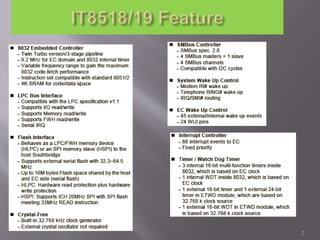
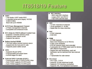
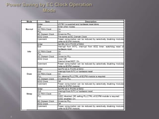
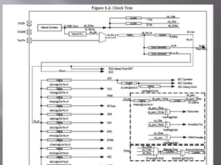
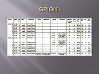
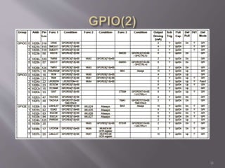


The document serves as a comprehensive training guide on embedded controllers and BIOS interactions in laptop technologies, detailing various system components such as power management, battery functionality, and hardware monitoring. Key topics include power sequences, load management, event notifications, and fan control mechanisms. It emphasizes best practices for pin management and protection from electrical overstress during operational scenarios.