Upper Dolpo trek lies hidden behind the Dhaulagiri Range in Nepal’s mid-western region where snow fed streams run off high mountains but few are perennial.
Mountain Mart Treks best trekking company specialized for wilderness tour, hiking, mountain climbing, Everest Base Camp trek and package trekking in Nepal Himalaya.
LF Energy Webinar: Electrical Grid Modelling and Simulation Through PowSyBl -...DanBrown980551
Do you want to learn how to model and simulate an electrical network from scratch in under an hour?
Then welcome to this PowSyBl workshop, hosted by Rte, the French Transmission System Operator (TSO)!
During the webinar, you will discover the PowSyBl ecosystem as well as handle and study an electrical network through an interactive Python notebook.
PowSyBl is an open source project hosted by LF Energy, which offers a comprehensive set of features for electrical grid modelling and simulation. Among other advanced features, PowSyBl provides:
- A fully editable and extendable library for grid component modelling;
- Visualization tools to display your network;
- Grid simulation tools, such as power flows, security analyses (with or without remedial actions) and sensitivity analyses;
The framework is mostly written in Java, with a Python binding so that Python developers can access PowSyBl functionalities as well.
What you will learn during the webinar:
- For beginners: discover PowSyBl's functionalities through a quick general presentation and the notebook, without needing any expert coding skills;
- For advanced developers: master the skills to efficiently apply PowSyBl functionalities to your real-world scenarios.
"Impact of front-end architecture on development cost", Viktor TurskyiFwdays
I have heard many times that architecture is not important for the front-end. Also, many times I have seen how developers implement features on the front-end just following the standard rules for a framework and think that this is enough to successfully launch the project, and then the project fails. How to prevent this and what approach to choose? I have launched dozens of complex projects and during the talk we will analyze which approaches have worked for me and which have not.
Dev Dives: Train smarter, not harder – active learning and UiPath LLMs for do...UiPathCommunity
💥 Speed, accuracy, and scaling – discover the superpowers of GenAI in action with UiPath Document Understanding and Communications Mining™:
See how to accelerate model training and optimize model performance with active learning
Learn about the latest enhancements to out-of-the-box document processing – with little to no training required
Get an exclusive demo of the new family of UiPath LLMs – GenAI models specialized for processing different types of documents and messages
This is a hands-on session specifically designed for automation developers and AI enthusiasts seeking to enhance their knowledge in leveraging the latest intelligent document processing capabilities offered by UiPath.
Speakers:
👨🏫 Andras Palfi, Senior Product Manager, UiPath
👩🏫 Lenka Dulovicova, Product Program Manager, UiPath
JMeter webinar - integration with InfluxDB and GrafanaRTTS
Watch this recorded webinar about real-time monitoring of application performance. See how to integrate Apache JMeter, the open-source leader in performance testing, with InfluxDB, the open-source time-series database, and Grafana, the open-source analytics and visualization application.
In this webinar, we will review the benefits of leveraging InfluxDB and Grafana when executing load tests and demonstrate how these tools are used to visualize performance metrics.
Length: 30 minutes
Session Overview
-------------------------------------------
During this webinar, we will cover the following topics while demonstrating the integrations of JMeter, InfluxDB and Grafana:
- What out-of-the-box solutions are available for real-time monitoring JMeter tests?
- What are the benefits of integrating InfluxDB and Grafana into the load testing stack?
- Which features are provided by Grafana?
- Demonstration of InfluxDB and Grafana using a practice web application
To view the webinar recording, go to:
https://www.rttsweb.com/jmeter-integration-webinar
Key Trends Shaping the Future of Infrastructure.pdfCheryl Hung
Keynote at DIGIT West Expo, Glasgow on 29 May 2024.
Cheryl Hung, ochery.com
Sr Director, Infrastructure Ecosystem, Arm.
The key trends across hardware, cloud and open-source; exploring how these areas are likely to mature and develop over the short and long-term, and then considering how organisations can position themselves to adapt and thrive.
Let's dive deeper into the world of ODC! Ricardo Alves (OutSystems) will join us to tell all about the new Data Fabric. After that, Sezen de Bruijn (OutSystems) will get into the details on how to best design a sturdy architecture within ODC.
PHP Frameworks: I want to break free (IPC Berlin 2024)Ralf Eggert
In this presentation, we examine the challenges and limitations of relying too heavily on PHP frameworks in web development. We discuss the history of PHP and its frameworks to understand how this dependence has evolved. The focus will be on providing concrete tips and strategies to reduce reliance on these frameworks, based on real-world examples and practical considerations. The goal is to equip developers with the skills and knowledge to create more flexible and future-proof web applications. We'll explore the importance of maintaining autonomy in a rapidly changing tech landscape and how to make informed decisions in PHP development.
This talk is aimed at encouraging a more independent approach to using PHP frameworks, moving towards a more flexible and future-proof approach to PHP development.
Neuro-symbolic is not enough, we need neuro-*semantic*Frank van Harmelen
Neuro-symbolic (NeSy) AI is on the rise. However, simply machine learning on just any symbolic structure is not sufficient to really harvest the gains of NeSy. These will only be gained when the symbolic structures have an actual semantics. I give an operational definition of semantics as “predictable inference”.
All of this illustrated with link prediction over knowledge graphs, but the argument is general.
UiPath Test Automation using UiPath Test Suite series, part 3DianaGray10
Welcome to UiPath Test Automation using UiPath Test Suite series part 3. In this session, we will cover desktop automation along with UI automation.
Topics covered:
UI automation Introduction,
UI automation Sample
Desktop automation flow
Pradeep Chinnala, Senior Consultant Automation Developer @WonderBotz and UiPath MVP
Deepak Rai, Automation Practice Lead, Boundaryless Group and UiPath MVP
Essentials of Automations: Optimizing FME Workflows with ParametersSafe Software
Are you looking to streamline your workflows and boost your projects’ efficiency? Do you find yourself searching for ways to add flexibility and control over your FME workflows? If so, you’re in the right place.
Join us for an insightful dive into the world of FME parameters, a critical element in optimizing workflow efficiency. This webinar marks the beginning of our three-part “Essentials of Automation” series. This first webinar is designed to equip you with the knowledge and skills to utilize parameters effectively: enhancing the flexibility, maintainability, and user control of your FME projects.
Here’s what you’ll gain:
- Essentials of FME Parameters: Understand the pivotal role of parameters, including Reader/Writer, Transformer, User, and FME Flow categories. Discover how they are the key to unlocking automation and optimization within your workflows.
- Practical Applications in FME Form: Delve into key user parameter types including choice, connections, and file URLs. Allow users to control how a workflow runs, making your workflows more reusable. Learn to import values and deliver the best user experience for your workflows while enhancing accuracy.
- Optimization Strategies in FME Flow: Explore the creation and strategic deployment of parameters in FME Flow, including the use of deployment and geometry parameters, to maximize workflow efficiency.
- Pro Tips for Success: Gain insights on parameterizing connections and leveraging new features like Conditional Visibility for clarity and simplicity.
We’ll wrap up with a glimpse into future webinars, followed by a Q&A session to address your specific questions surrounding this topic.
Don’t miss this opportunity to elevate your FME expertise and drive your projects to new heights of efficiency.
Connector Corner: Automate dynamic content and events by pushing a buttonDianaGray10
Here is something new! In our next Connector Corner webinar, we will demonstrate how you can use a single workflow to:
Create a campaign using Mailchimp with merge tags/fields
Send an interactive Slack channel message (using buttons)
Have the message received by managers and peers along with a test email for review
But there’s more:
In a second workflow supporting the same use case, you’ll see:
Your campaign sent to target colleagues for approval
If the “Approve” button is clicked, a Jira/Zendesk ticket is created for the marketing design team
But—if the “Reject” button is pushed, colleagues will be alerted via Slack message
Join us to learn more about this new, human-in-the-loop capability, brought to you by Integration Service connectors.
And...
Speakers:
Akshay Agnihotri, Product Manager
Charlie Greenberg, Host
GenAISummit 2024 May 28 Sri Ambati Keynote: AGI Belongs to The Community in O...
Advanced motion controls azbdc40a8
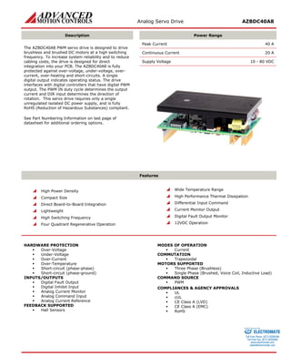
1. Analog Servo Drive AZBDC40A8
Description
Power Range
The AZBDC40A8 PWM servo drive is designed to drive brushless and brushed DC motors at a high switching frequency. To increase system reliability and to reduce cabling costs, the drive is designed for direct integration into your PCB. The AZBDC40A8 is fully protected against over-voltage, under-voltage, over- current, over-heating and short-circuits. A single digital output indicates operating status. The drive interfaces with digital controllers that have digital PWM output. The PWM IN duty cycle determines the output current and DIR input determines the direction of rotation. This servo drive requires only a single unregulated isolated DC power supply, and is fully RoHS (Reduction of Hazardous Substances) compliant.
See Part Numbering Information on last page of datasheet for additional ordering options.
Peak Current 40 A
Continuous Current 20 A
Supply Voltage 10 - 80 VDC
Features
High Power Density
Compact Size
Direct Board-to-Board Integration
Lightweight
High Switching Frequency
Four Quadrant Regenerative Operation
Wide Temperature Range
High Performance Thermal Dissipation
Differential Input Command
Current Monitor Output
Digital Fault Output Monitor
12VDC Operation
HARDWARE PROTECTION
Over-Voltage
Under-Voltage
Over-Current
Over-Temperature
Short-circuit (phase-phase)
Short-circuit (phase-ground)
INPUTS/OUTPUTS
Digital Fault Output
Digital Inhibit Input
Analog Current Monitor
Analog Command Input
Analog Current Reference
FEEDBACK SUPPORTED
Hall Sensors
MODES OF OPERATION
Current
COMMUTATION
Trapezoidal
MOTORS SUPPORTED
Three Phase (Brushless)
Single Phase (Brushed, Voice Coil, Inductive Load)
COMMAND SOURCE
PWM
COMPLIANCES & AGENCY APPROVALS
UL
cUL
CE Class A (LVD)
CE Class A (EMC)
RoHS
ELECTROMATE
Toll Free Phone (877) SERVO98
Toll Free Fax (877) SERV099
www.electromate.com
sales@electromate.com
Sold & Serviced By:
2. Analog Servo Drive AZBDC40A8
BLOCK DIAGRAM
Information on Approvals and Compliances
US and Canadian safety compliance with UL 508c, the industrial standard for power conversion electronics. UL registered under file number E140173. Note that machine components compliant with UL are considered UL registered as opposed to UL listed as would be the case for commercial products.
Compliant with European CE for both the Class A EMC Directive 2004/108/EC on Electromagnetic Compatibility (specifically EN 61000-6-4:2007 and EN 61000-6-2:2005) and LVD requirements of directive 2006/95/EC (specifically EN 60204-1:2006), a low voltage directive to protect users from electrical shock.
RoHS (Reduction of Hazardous Substances) is intended to prevent hazardous substances such as lead from being manufactured in electrical and electronic equipment.
ELECTROMATE
Toll Free Phone (877) SERVO98
Toll Free Fax (877) SERV099
www.electromate.com
sales@electromate.com
Sold & Serviced By:
3. Analog Servo Drive AZBDC40A8
SPECIFICATIONS
Power Specifications
Description
Units
Value
DC Supply Voltage Range
VDC
10 - 80
DC Bus Under Voltage Limit
VDC
9
DC Bus Over Voltage Limit
VDC
88
Maximum Peak Output Current1
A
40
Maximum Continuous Output Current
A
20
Maximum Continuous Output Power
W
1520
Maximum Power Dissipation at Continuous Current
W
80
Minimum Load Inductance (Line-To-Line)2
μH
100
Low Voltage Supply Outputs
-
+6 VDC (30 mA)
Switching Frequency
kHz
31
Control Specifications
Description
Units
Value
Command Sources
-
PWM
PWM Input Frequency Range
kHz
10 - 25
Feedback Supported
-
Halls
Commutation Methods
-
Trapezoidal
Modes of Operation
-
Current
Motors Supported
-
Three Phase (Brushless), Single Phase (Brushed, Voice Coil, Inductive Load)
Hardware Protection
-
Invalid Commutation Feedback, Over Current, Over Temperature, Over Voltage, Under Voltage, Short Circuit (Phase-Phase & Phase-Ground)
Mechanical Specifications
Description
Units
Value
Agency Approvals
-
CE Class A (EMC), CE Class A (LVD), cUL, RoHS, UL
Size (H x W x D)
mm (in)
76.2 x 50.8 x 22.86 (3 x 2 x 0.9)
Weight
g (oz)
119.7 (4.2)
Heatsink (Base) Temperature Range3
°C (°F)
0 - 75 (32 - 167)
Storage Temperature Range
°C (°F)
-40 - 85 (-40 - 185)
P1 Connector
-
16-pin, 2.54 mm spaced header
P2 Connector
-
22-pin, 2.54 mm spaced, dual-row header
P3 Connector
-
22-pin, 2.54 mm spaced, dual-row header
Notes
1. Maximum duration of peak current is ~2 seconds. Peak RMS value must not exceed continuous current rating of the drive.
2. Lower inductance is acceptable for bus voltages well below maximum. Use external inductance to meet requirements.
3. Additional cooling and/or heatsink may be required to achieve rated performance.
ELECTROMATE
Toll Free Phone (877) SERVO98
Toll Free Fax (877) SERV099
www.electromate.com
sales@electromate.com
Sold & Serviced By:
4. Analog Servo Drive AZBDC40A8
PIN FUNCTIONS
P1 - Signal Connector
Pin
Name
Description / Notes
I/O
1
PWM / IN
10 – 25 kHz pulse width modulated digital input command (+5V). Input duty cycle commands the output current.
I
2
SIGNAL GND
Signal Ground
GND
3
DIRECTION
Direction Input (+5 V)
I
4
CURRENT MONITOR
Current Monitor. Analog output signal proportional to the actual current output. Scaling is 13.5 A/V. Measure relative to signal ground.
O
5
INHIBIT IN
TTL level (+5 V) inhibit/enable input. Leave open to enable drive. Pull to ground to inhibit drive. Inhibit turns off all power devices.
I
6
+V HALL OUT
Low Power Supply For Hall Sensors (+6 V @ 30 mA). Referenced to signal ground. Short circuit protected.
O
7
SIGNAL GND
Signal Ground
GND
8
HALL 1
Single-ended Hall/Commutation Sensor Inputs (+5 V logic level)
I
9
HALL 2*
I
10
HALL 3
I
11
CURRENT REFERENCE
Measures the command signal to the internal current-loop. This pin has a maximum output of ±7.3 V when the drive outputs maximum peak current. Measure relative to signal ground.
O
12
FAULT OUT
TTL level (+5 V) output becomes high when power devices are disabled due to at least one of the following conditions: inhibit, invalid Hall state, output short circuit, over voltage, over temperature, power-up reset.
O
13
RESERVED
Reserved
-
14
RESERVED
-
15
RESERVED
-
16
RESERVED
-
P2 and P3 - Power Connector
Pin
Name
Description / Notes
I/O
1b
1a
HIGH VOLTAGE
DC Power Input. 3A Continuous Current Rating Per Pin. Requires at least 470 μF / 100 V external electrolytic capacitor connected as close as possible to pins between High Voltage and Power Ground.
I
2b
2a
HIGH VOLTAGE
I
3b
NC
Not Connected (Reserved)
-
3a
NC (KEY)
Key: No Connection (pin removed) for P2. Not Connected (Reserved) for P3.
-
4b
4b
PWR GND
Power Ground (Common With Signal Ground). 3A Continuous Current Rating Per Pin.
GND
5b
5a
PWR GND
GND
6b
6a
MOTOR C
Motor Phase Outputs. Current output distributed equally across both P2 and P3 connectors – 8 pins per motor phase, 3A continuous current carrying capacity per pin.
O
7b
7a
MOTOR C
O
8b
8a
MOTOR B
O
9b
9a
MOTOR B
O
10b
10a
MOTOR A
O
11b
11a
MOTOR A
O
*For use with Single Phase (Brushed) motors, ground Hall 2 and only connect motor leads to Motor A and Motor B.
HARDWARE SETTINGS
Jumper Settings
Jumpers are SMT, 0 ohm resistors located on the underside of the drive PCB. By default, the drive is configured with the jumpers installed. Typical drive operation will not require the jumpers to be removed. Please contact the factory before jumper removal.
Jumper
Description
Configuration
SMT Jumper (0Ω Resistor)
Not Installed
Installed
JE1
Inhibit logic. Sets the logic level of inhibit pins. Labeled JE1 on the PCB of the drive.
Low Enable
Low Inhibit
JE2
Hall sensor phasing. Selects 120 or 60 degree commutation phasing. Labeled JE2 on the PCB of the drive.
60 degree
120 degree
ELECTROMATE
Toll Free Phone (877) SERVO98
Toll Free Fax (877) SERV099
www.electromate.com
sales@electromate.com
Sold & Serviced By:
5. Analog Servo Drive AZBDC40A8
MECHANICAL INFORMATION
P1 - Signal Connector
Connector Information
16-pin, 2.54 mm spaced header
Mating Connector
Details
Samtec: BCS-116-L-S-PE
Included with Drive
No
PWM / IN1SIGNAL GND2DIRECTION3CURRENT MONITOR4INHIBIT IN5+V HALL OUT6SIGNAL GND7HALL 18HALL 29HALL 310CURRENT REFERENCE11FAULT OUT12
P2 - Power Connector
Connector Information
22-pin, 2.54 mm spaced, dual-row header
Mating Connector
Details
Samtec: SSM-111-L-DV
Included with Drive
No
MOTOR A11aMOTOR A11bMOTOR A10aMOTOR A10bMOTOR B9aMOTOR B9bMOTOR B8aMOTOR B8bMOTOR C7aMOTOR C7bMOTOR C6aMOTOR C6bPWR GND5aPWR GND4aPWR GND5bNC3bPWR GND4bHIGH VOLTAGE2bHIGH VOLTAGE1bHIGH VOLTAGE1aHIGH VOLTAGE2aNC (KEY)3a
P3 - Power Connector
Connector Information
22-pin, 2.54 mm spaced, dual-row header
Mating Connector
Details
Samtec: SSM-111-L-DV
Included with Drive
No
MOTOR A11aMOTOR A11bMOTOR A10aMOTOR A10bMOTOR B9aMOTOR B9bMOTOR B8aMOTOR B8bMOTOR C7aMOTOR C7bMOTOR C6aMOTOR C6bPWR GND5aPWR GND4aPWR GND5bNC3bPWR GND4bHIGH VOLTAGE2bHIGH VOLTAGE1bHIGH VOLTAGE1aHIGH VOLTAGE2aNC3a
ELECTROMATE
Toll Free Phone (877) SERVO98
Toll Free Fax (877) SERV099
www.electromate.com
sales@electromate.com
Sold & Serviced By:
7. Analog Servo Drive AZBDC40A8
PART NUMBERING INFORMATION
A840- Blank:Current Mode onlyE:Encoder Velocity Mode AvailableH:Hall Velocity Mode AvailableBDCAZ Analog Drive SeriesAZDrive TypeB:Brushless/BrushedBDC:Brushless/Brushed, PWM CommandFeedback Supported6:6 Peak, 3 Continuous8:80Inverted Inhibit LogicINV: *Options available for orders with sufficient volume. Contact ADVANCED Motion Controls for more information. 10:10 Peak, 6 Continuous20:175Peak Current (Amps) 12:12 Peak, 6 ContinuousMax DC Bus Voltage (~1:10 in Volts) Additional Options* 25:25 Peak, 12.5 Continuous25:25 Peak, 12.5 Continuous40:40 Peak, 20 Continuous80V Models175V Models60:60 Peak, 30 Continuous10:10 Peak, 5 Continuous40V Models4:40
ADVANCED Motion Controls AZ series of servo drives are available in many configurations. Note that not all possible part number combinations are offered as standard drives. All models listed in the selection tables of the website are readily available, standard product offerings.
ADVANCED Motion Controls also has the capability to promptly develop and deliver specified products for OEMs with volume requests. Our Applications and Engineering Departments will work closely with your design team through all stages of development in order to provide the best servo drive solution for your system. Equipped with on-site manufacturing for quick- turn customs capabilities, ADVANCED Motion Controls utilizes our years of engineering and manufacturing expertise to decrease your costs and time-to-market while increasing system quality and reliability.
Examples of Modifications and Customized Products
Integration of Drive into Motor Housing
Integrate OEM Circuitry onto Drive PCB
Mount OEM PCB onto Drive Without Cables
Custom Control Loop Tuned to Motor Characteristics
Multi-axis Configuration for Compact System
Custom I/O Interface for System Compatibility
Custom PCB and Baseplate for Optimized Footprint
Preset Switches and Pots to Reduce User Setup
RTV/Epoxy Components for High Vibration
Optimized Switching Frequency
OEM Specified Connectors for Instant Compatibility
Ramped Velocity Command for Smooth Acceleration
OEM Specified Silkscreen for Custom Appearance
Remove Unused Features to Reduce OEM Cost
Increased Thermal Limits for High Temp. Operation
Application Specific Current and Voltage Limits
Feel free to contact Applications Engineering for further information and details.
Available Accessories
ADVANCED Motion Controls offers a variety of accessories designed to facilitate drive integration into a servo system.
Visit www.a-m-c.com to see which accessories will assist with your application design and implementation.
Power Supplies
Shunt Regulators
Mounting Card
MC1XAZ01-HR
Filter Cards
To Motor
Drive(s)
All specifications in this document are subject to change without written notice. Actual product may differ from pictures provided in this document.
ELECTROMATE
Toll Free Phone (877) SERVO98
Toll Free Fax (877) SERV099
www.electromate.com
sales@electromate.com
Sold & Serviced By: