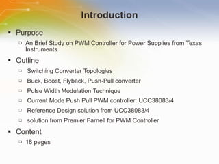
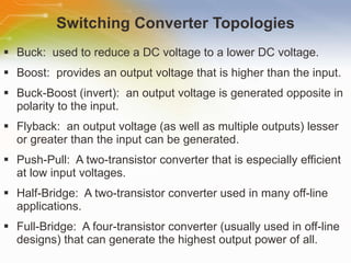
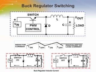
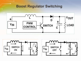
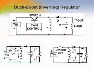
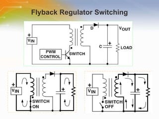
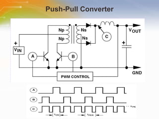
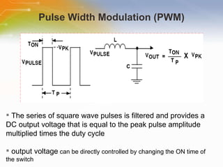
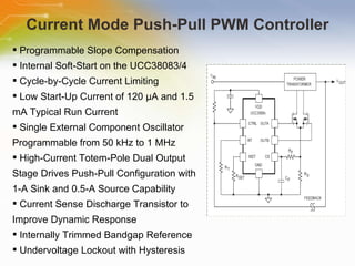
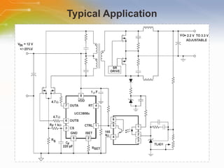
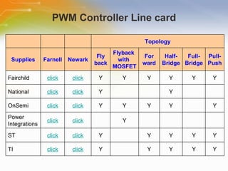
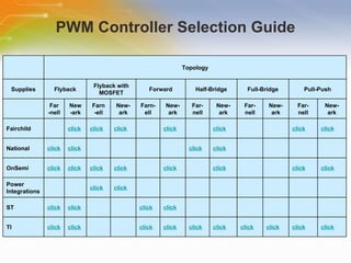
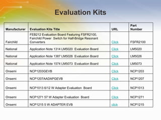
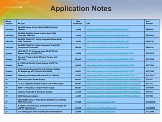
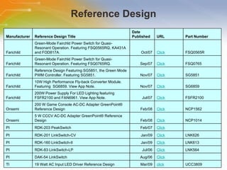
PWM Controller for Power Supplies
Introduction Purpose An   Brief   Study   on   PWM   Controller   for   Power   Supplies   from   Texas   Instruments Outline Switching   Converter   Topologies Buck,   Boost,   Flyback,   Push-Pull   converter Pulse   Width   Modulation   Technique Current   Mode   Push   Pull   PWM   controller:   UCC38083/4 Reference   Design   solution   from   UCC38083/4 solution   from   Premier   Farnell   for   PWM   Controller Content 18   pages
Switching Converter Topologies Buck:  used to reduce a DC voltage to a lower DC voltage. Boost:  provides an output voltage that is higher than the input. Buck-Boost (invert):  an output voltage is generated opposite in polarity to the input. Flyback:  an output voltage (as well as multiple outputs) lesser or greater than the input can be generated.  Push-Pull:  A two-transistor converter that is especially efficient at low input voltages. Half-Bridge:  A two-transistor converter used in many off-line applications. Full-Bridge:  A four-transistor converter (usually used in off-line designs) that can generate the highest output power of all.
Buck Regulator Switching Buck Regulator Inductor Current
Boost Regulator Switching
Buck-Boost (Inverting) Regulator
Flyback Regulator Switching
Push-Pull Converter
Pulse Width Modulation (PWM) The   series   of   square   wave   pulses   is   filtered   and   provides   a   DC   output   voltage   that   is   equal   to   the   peak   pulse   amplitude   multiplied   times   the   duty   cycle output   voltage   can   be   directly   controlled   by   changing   the   ON   time   of   the   switch
Current Mode Push-Pull PWM Controller Programmable Slope Compensation Internal Soft-Start on the UCC38083/4 Cycle-by-Cycle Current Limiting Low Start-Up Current of 120 μA and 1.5 mA Typical Run Current Single External Component Oscillator Programmable from 50 kHz to 1 MHz High-Current Totem-Pole Dual Output Stage Drives Push-Pull Configuration with 1-A Sink and 0.5-A Source Capability  Current Sense Discharge Transistor to Improve Dynamic Response Internally Trimmed Bandgap Reference Undervoltage Lockout with Hysteresis
Typical Application
Operational Waveforms Typical Slope Compensation Waveforms at 80% Duty Cycle
PWM Controller Line card       Topology Supplies Farnell Newark Fly back Flyback  with  MOSFET For ward Half- Bridge Full- Bridge Pull- Push Fairchild click click Y Y Y Y Y Y National click click Y     Y     OnSemi click click Y Y Y Y   Y Power  Integrations  click click   Y         ST click click Y   Y Y Y Y TI click click Y   Y Y Y Y
PWM Controller Selection Guide   Topology Supplies Flyback Flyback with MOSFET Forward Half-Bridge Full-Bridge Pull-Push   Far -nell New -ark Farn -ell New- ark Farn- ell New- ark Far- nell New- ark Far- nell New- ark Far- nell New- ark Fairchild   click click click   click   click   click click National click click       click click       OnSemi click click click click click click   click click Power  Integrations      click click               ST click click   click click           TI click click   click click click click click click click click
Evaluation Kits Manufacturer Evaluation Kits Title URL Part  Number Fairchild FEB212 Evaluation Board Featuring FSFR2100,  Fairchild Power  Switch for Half-Bridge Resonant  Converters  Click FSFR2100 National Application Note 1314 LM5020  Evaluation Board Click LM5020 National Application Note 1387 LM5026  Evaluation Board Click LM5026 National Application Note 1574 LM5073  Evaluation Board Click LM5073 Onsemi NCP1203GEVB Click NCP1203 Onsemi NCP1207AADAPGEVB Click NCP1207 Onsemi NCP1013 6/12 W Adapter Evaluation  Board Click NCP1013 Onsemi NCP1271 57 W Adapter Evaluation  Board Click NCP1271 Onsemi NCP1215 5 W ADAPTER EVB click NCP1215
Application Notes Manuf -acturer AN Title Date  Published URL Part  Number Farichild AN-4129: Green Current Mode PWM Controller  FAN7601  Jul/09 http://www.fairchildsemi.com/an/AN/AN-4129.pdf FAN7601 Farichild AN-6014: AN-6014 Green Current Mode PWM  Controller FAN7602 Jul/09 http://www.fairchildsemi.com/an/AN/AN-6014.pdf FAN7602 Farichild AN-6753: FAN6753 ? Highly Integrated Green-Mode  PWM Controller  Jul/09 http://www.fairchildsemi.com/an/AN/AN-6753.pdf FAN6753 Farichild AN-6083: FAN6791- Highly Integrated, Dual-PWM  Combination Controller Mar/09 http://www.fairchildsemi.com/an/AN/AN-6083.pdf FAN6791 Onsemi 48 W, 24 V/7.5 V Universal Input AC-DC Printer  Adapter Using the NCP1219 Jul/09 http://www.onsemi.com/pub/Collateral/AND8393-D.PDF NCP1219 Onsemi Tips and Tricks to Build Efficient Circuits with  NCP1200 May/03 http://www.onsemi.com/pub/Collateral/AND8069-D.PDF NCP1200 Onsemi A 70 W Low Standby Power Supply w/NCP120x  Series Apr/03 http://www.onsemi.com/pub/Collateral/AND8076-D.PDF NCP120x Onsemi Implementing Constant Current Constant Voltage  AC Adapter by NCP1200 and NCP4300A Feb/01 http://www.onsemi.com/pub/Collateral/AND8042-D.PDF NCP1200 Onsemi Designing Converters with the NCP101X Family Oct/03 http://www.onsemi.com/pub/Collateral/AND8134-D.PDF NCP101x PI 30 W Set-top Box Power Supply Nov/07 http://www.powerint.com/sites/default/files/PDFFiles/di162.pdf TOP257 PI 7.5 W (13 W peak) Multiple Output STB Power Supply Nov/07 http://www.powerint.com/sites/default/files/PDFFiles/di115.pdf TNY376 PI 43 W / 57 W (peak), 5 Output Power Supply May/01 http://www.powerint.com/sites/default/files/PDFFiles/epr13.pdf TOP246Y PI Ultra-low Profile 65 W Notebook Adapter Jun/09 http://www.powerint.com/sites/default/files/PDFFiles/di196.pdf TOP261 PI 65 W Notebook Adapter Jul/08 http://www.powerint.com/sites/default/files/PDFFiles/di182.pdf TOP259 TI UCC38C42 Family of High-Speed BiCMOS Current-Mode  PWM Controllers Feb/02 http://www.ti.com/litv/pdf/slua257 UCC38C42 TI A 300-W, Universal Input, Isolated PFC Power Supply for LCD TV Applications Dec/08 http://www.ti.com/litv/pdf/sluu341b UCC25600 TI UCC2895 Layout and Grounding Recommendations Apr/09 http://www.ti.com/litv/pdf/slua501 UCC2895
Reference Design Manufacturer Reference Design Title Date  Published URL Part Number Farichild Green-Mode Fairchld Power Switch for Quasi- Resonant Operation. Featuring FSQ0565RQ, KA431A  and FOD817A.  Oct/07 Click FSQ0565R Farichild Green-Mode Fairchld Power Switch for Quasi- Resonant Operation. Featuring FSQ0765RQ. Sep/07 Click FSQ0765 Farichild Reference Design Featuring SG5851, the Green Mode  PWM Controller. Featuring SG5851. Nov/07 Click SG5851 Farichild 10W High Performance Fly-back Converter Module.  Featuring  SG6859. View App Note.  Nov/07 Click SG6859 Farichild 200W Power Supply For LED Lighting featuring  FSFR2100 and FAN6961. View App Note.  Jul/07 Click FSFR2100 Onsemi 200 W Game Console AC-DC Adapter GreenPoint®  Reference Design Feb/08 Click NCP1562 Onsemi 5 W CCCV AC-DC Adapter GreenPoint® Reference  Design Feb/08 Click NCP1014 PI RDK-203 PeakSwitch Feb/07 Click   PI RDK-201 LinkSwitch-CV Jan/09 Click LNK626 PI RDK-160 LinkSwitch-II Jan/09 Click LNK613 PI RDK-83 LinkSwitch-LP Jul/06 Click LNK564 PI DAK-54 LinkSwitch Aug/06 Click   TI 19 Watt AC Input LED Driver Reference Design Mar/09 click UCC3809
Additional Resource For ordering  PWM Controller , please click the part list or Call our sales hotline For more product information go to Click Here Visit element14 to post your question   www.element-14.com For additional inquires contact our technical service hotline or even use our “Live Technical Chat” online facility Newark Farnell

PWM Controller for Power Supplies

  • 1.
    PWM Controller forPower Supplies
  • 2.
    Introduction Purpose An Brief Study on PWM Controller for Power Supplies from Texas Instruments Outline Switching Converter Topologies Buck, Boost, Flyback, Push-Pull converter Pulse Width Modulation Technique Current Mode Push Pull PWM controller: UCC38083/4 Reference Design solution from UCC38083/4 solution from Premier Farnell for PWM Controller Content 18 pages
  • 3.
    Switching Converter TopologiesBuck: used to reduce a DC voltage to a lower DC voltage. Boost: provides an output voltage that is higher than the input. Buck-Boost (invert): an output voltage is generated opposite in polarity to the input. Flyback: an output voltage (as well as multiple outputs) lesser or greater than the input can be generated. Push-Pull: A two-transistor converter that is especially efficient at low input voltages. Half-Bridge: A two-transistor converter used in many off-line applications. Full-Bridge: A four-transistor converter (usually used in off-line designs) that can generate the highest output power of all.
  • 4.
    Buck Regulator SwitchingBuck Regulator Inductor Current
  • 5.
  • 6.
  • 7.
  • 8.
  • 9.
    Pulse Width Modulation(PWM) The series of square wave pulses is filtered and provides a DC output voltage that is equal to the peak pulse amplitude multiplied times the duty cycle output voltage can be directly controlled by changing the ON time of the switch
  • 10.
    Current Mode Push-PullPWM Controller Programmable Slope Compensation Internal Soft-Start on the UCC38083/4 Cycle-by-Cycle Current Limiting Low Start-Up Current of 120 μA and 1.5 mA Typical Run Current Single External Component Oscillator Programmable from 50 kHz to 1 MHz High-Current Totem-Pole Dual Output Stage Drives Push-Pull Configuration with 1-A Sink and 0.5-A Source Capability Current Sense Discharge Transistor to Improve Dynamic Response Internally Trimmed Bandgap Reference Undervoltage Lockout with Hysteresis
  • 11.
  • 12.
    Operational Waveforms TypicalSlope Compensation Waveforms at 80% Duty Cycle
  • 13.
    PWM Controller Linecard       Topology Supplies Farnell Newark Fly back Flyback with MOSFET For ward Half- Bridge Full- Bridge Pull- Push Fairchild click click Y Y Y Y Y Y National click click Y     Y     OnSemi click click Y Y Y Y   Y Power Integrations click click   Y         ST click click Y   Y Y Y Y TI click click Y   Y Y Y Y
  • 14.
    PWM Controller SelectionGuide   Topology Supplies Flyback Flyback with MOSFET Forward Half-Bridge Full-Bridge Pull-Push   Far -nell New -ark Farn -ell New- ark Farn- ell New- ark Far- nell New- ark Far- nell New- ark Far- nell New- ark Fairchild   click click click   click   click   click click National click click       click click       OnSemi click click click click click click   click click Power Integrations     click click               ST click click   click click           TI click click   click click click click click click click click
  • 15.
    Evaluation Kits ManufacturerEvaluation Kits Title URL Part Number Fairchild FEB212 Evaluation Board Featuring FSFR2100, Fairchild Power Switch for Half-Bridge Resonant Converters Click FSFR2100 National Application Note 1314 LM5020 Evaluation Board Click LM5020 National Application Note 1387 LM5026 Evaluation Board Click LM5026 National Application Note 1574 LM5073 Evaluation Board Click LM5073 Onsemi NCP1203GEVB Click NCP1203 Onsemi NCP1207AADAPGEVB Click NCP1207 Onsemi NCP1013 6/12 W Adapter Evaluation Board Click NCP1013 Onsemi NCP1271 57 W Adapter Evaluation Board Click NCP1271 Onsemi NCP1215 5 W ADAPTER EVB click NCP1215
  • 16.
    Application Notes Manuf-acturer AN Title Date Published URL Part Number Farichild AN-4129: Green Current Mode PWM Controller FAN7601 Jul/09 http://www.fairchildsemi.com/an/AN/AN-4129.pdf FAN7601 Farichild AN-6014: AN-6014 Green Current Mode PWM Controller FAN7602 Jul/09 http://www.fairchildsemi.com/an/AN/AN-6014.pdf FAN7602 Farichild AN-6753: FAN6753 ? Highly Integrated Green-Mode PWM Controller Jul/09 http://www.fairchildsemi.com/an/AN/AN-6753.pdf FAN6753 Farichild AN-6083: FAN6791- Highly Integrated, Dual-PWM Combination Controller Mar/09 http://www.fairchildsemi.com/an/AN/AN-6083.pdf FAN6791 Onsemi 48 W, 24 V/7.5 V Universal Input AC-DC Printer Adapter Using the NCP1219 Jul/09 http://www.onsemi.com/pub/Collateral/AND8393-D.PDF NCP1219 Onsemi Tips and Tricks to Build Efficient Circuits with NCP1200 May/03 http://www.onsemi.com/pub/Collateral/AND8069-D.PDF NCP1200 Onsemi A 70 W Low Standby Power Supply w/NCP120x Series Apr/03 http://www.onsemi.com/pub/Collateral/AND8076-D.PDF NCP120x Onsemi Implementing Constant Current Constant Voltage AC Adapter by NCP1200 and NCP4300A Feb/01 http://www.onsemi.com/pub/Collateral/AND8042-D.PDF NCP1200 Onsemi Designing Converters with the NCP101X Family Oct/03 http://www.onsemi.com/pub/Collateral/AND8134-D.PDF NCP101x PI 30 W Set-top Box Power Supply Nov/07 http://www.powerint.com/sites/default/files/PDFFiles/di162.pdf TOP257 PI 7.5 W (13 W peak) Multiple Output STB Power Supply Nov/07 http://www.powerint.com/sites/default/files/PDFFiles/di115.pdf TNY376 PI 43 W / 57 W (peak), 5 Output Power Supply May/01 http://www.powerint.com/sites/default/files/PDFFiles/epr13.pdf TOP246Y PI Ultra-low Profile 65 W Notebook Adapter Jun/09 http://www.powerint.com/sites/default/files/PDFFiles/di196.pdf TOP261 PI 65 W Notebook Adapter Jul/08 http://www.powerint.com/sites/default/files/PDFFiles/di182.pdf TOP259 TI UCC38C42 Family of High-Speed BiCMOS Current-Mode PWM Controllers Feb/02 http://www.ti.com/litv/pdf/slua257 UCC38C42 TI A 300-W, Universal Input, Isolated PFC Power Supply for LCD TV Applications Dec/08 http://www.ti.com/litv/pdf/sluu341b UCC25600 TI UCC2895 Layout and Grounding Recommendations Apr/09 http://www.ti.com/litv/pdf/slua501 UCC2895
  • 17.
    Reference Design ManufacturerReference Design Title Date Published URL Part Number Farichild Green-Mode Fairchld Power Switch for Quasi- Resonant Operation. Featuring FSQ0565RQ, KA431A and FOD817A. Oct/07 Click FSQ0565R Farichild Green-Mode Fairchld Power Switch for Quasi- Resonant Operation. Featuring FSQ0765RQ. Sep/07 Click FSQ0765 Farichild Reference Design Featuring SG5851, the Green Mode PWM Controller. Featuring SG5851. Nov/07 Click SG5851 Farichild 10W High Performance Fly-back Converter Module. Featuring SG6859. View App Note. Nov/07 Click SG6859 Farichild 200W Power Supply For LED Lighting featuring FSFR2100 and FAN6961. View App Note. Jul/07 Click FSFR2100 Onsemi 200 W Game Console AC-DC Adapter GreenPoint® Reference Design Feb/08 Click NCP1562 Onsemi 5 W CCCV AC-DC Adapter GreenPoint® Reference Design Feb/08 Click NCP1014 PI RDK-203 PeakSwitch Feb/07 Click   PI RDK-201 LinkSwitch-CV Jan/09 Click LNK626 PI RDK-160 LinkSwitch-II Jan/09 Click LNK613 PI RDK-83 LinkSwitch-LP Jul/06 Click LNK564 PI DAK-54 LinkSwitch Aug/06 Click   TI 19 Watt AC Input LED Driver Reference Design Mar/09 click UCC3809
  • 18.
    Additional Resource Forordering PWM Controller , please click the part list or Call our sales hotline For more product information go to Click Here Visit element14 to post your question www.element-14.com For additional inquires contact our technical service hotline or even use our “Live Technical Chat” online facility Newark Farnell

Editor's Notes

  • #2 Welcome to the training module on [PWM Controllers for Power Supplies]
  • #3 This training module will Introduce you to PWM controller and its’ different Topologies.
  • #4 The switching regulator is increasing in popularity because it offers the advantages of higher power conversion efficiency and increased design flexibility multiple output voltages of different polarities can be generated from a single input voltage.
  • #5 The most commonly used switching converter is the Buck, which is used to down-convert a DC voltage to a lower DC voltage of the same polarity. This is essential in systems that use distributed power rails (like 24V to 48V), which must be locally converted to 15V, 12V or 5V with very little power loss. The Buck converter uses a transistor as a switch that alternately connects and disconnects the input voltage to an inductor. When the switch turns on, the input voltage is connected to the inductor. The difference between the input and output voltages is then forced across the inductor, causing current through the inductor to increase.
  • #6 The Boost regulator takes a DC input voltage and produces a DC output voltage that is higher in value than the input (but of the same polarity). Whenever the switch is on, the input voltage is forced across the inductor which causes the current through it to increase (ramp up). When the switch is off, the decreasing inductor current forces the "switch" end of the inductor to swing positive. This forward biases the diode, allowing the capacitor to charge up to a voltage that is higher than the input voltage. During steady-state operation, the inductor current flows into both the output capacitor and the load during the switch off time. When the switch is on, the load current is supplied only by the capacitor.
  • #7 The Buck-Boost or Inverting regulator takes a DC input voltage and produces a DC output voltage that is opposite in polarity to the input. The negative output voltage can be either larger or smaller in magnitude than the input voltage. When the switch is on, the input voltage is forced across the inductor, causing an increasing current flow through it. During the on time, the discharge of the output capacitor is the only source of load current. When the switch turns off, the decreasing current flow in the inductor causes the voltage at the diode end to swing negative. This action turns on the diode, allowing the current in the inductor to supply both the output capacitor and the load.
  • #8 The Flyback is the most versatile of all the topologies, allowing the designer to create one or more output voltages, some of which may be opposite in polarity. Flyback converters have gained popularity in battery-powered systems, where a single voltage must be converted into the required system voltages for example, +5V, +12V and -12V, with very high power conversion efficiency. The most important feature of the Flyback regulator is the transformer phasing, as shown by the dots on the primary and secondary windings. When the switch is on, the input voltage is forced across the transformer primary which causes an increasing flow of current through it.
  • #9 The Push-Pull converter uses two to transistors perform DC-DC conversion, The converter operates by turning on each transistor on alternate cycles (the two transistors are never on at the same time). Transformer secondary current flows at the same time as primary current. An important characteristic of a Push-Pull converter is that the switch transistors have to be able the stand off more than twice the input voltage
  • #10 All of the switching converters use a form of output voltage regulation known as Pulse Width Modulation (PWM). Put simply, the feedback loop adjusts (corrects) the output voltage by changing the ON time of the switching element in the converter.
  • #11 The UCC38083/4/5/6 is a family of BiCMOS pulse width modulation (PWM) controllers for dc-to-dc or off-line fixed-frequency current-mode switching power supplies. The dual output stages are configured for the push-pull topology. Both outputs switch at half the oscillator frequency using a toggle flip-flop. The dead time between the two outputs is typically 110 ns, limiting each output’s duty cycle to less than 50%.
  • #12 The application circuit shows an isolated 12-VIN to 2.5 VOUT push-pull converter with scalable output power (20 W to 200 W). Note that the pinout shown is for SOIC-8 and PDIP-8 packages
  • #13 OUTA and OUTB are shown at a duty cycle of 80%, with the associated voltage VRS across the current sense resistor of the primary push-pull power MOSFETs. The current flowing out of CS generates the ramp voltage across the filter resistor RF that is positioned between the power current sense resistor and the CS pin. This voltage is effectively added to VRS to provide slope compensation at VCS, pin 3. A capacitor CF is also recommended to filter the waveform at CS.
  • #14 This page gives PWM Controller Line card from different suppliers with different topologies from Premier Farnell.
  • #15 This page gives PWM Controller Selection Guide from different suppliers with different topologies from Premier Farnell.
  • #16 This page gives Evaluation Kits details from different suppliers from Premier Farnell.
  • #17 This page gives Application Notes details from different suppliers from Premier farnell.
  • #18 This page gives Reference Design details from different suppliers from Premier Farnell.
  • #19 Thank you for taking the time to view this presentation on “ [PWM Controller for Power Supplies]” . If you would like to learn more or go on to purchase some of these devices, you may either click on the part list link right beside the play button on the TechCast portal, or simply call our sales hotline. For more technical information you may either visit the [Texas Instruments] site, or if you would prefer to speak to someone live, please call our hotline number, or even use our ‘live chat’ online facility. You may visit element14 e-community to post your questions.