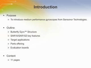
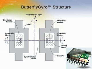
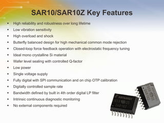
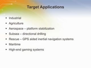
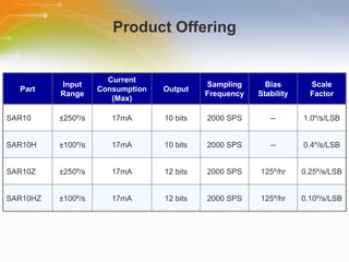
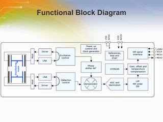
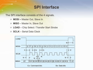
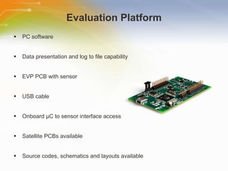
Medium Performance Gyroscopes Source: Sensonor Technologies AS
Introduction Purpose To introduce medium performance gyroscopes from Sensonor Technologies. Outline Butterfly Gyro ™ Structure SAR10/SAR10Z key features Target applications Parts offering Evaluation boards Content 11 pages
ButterflyGyro ™ Structure
SAR10/SAR10Z Key Features High reliability and robustness over long lifetime  Low vibration sensitivity  High overload and shock  Butterfly balanced design for high mechanical common mode rejection  Closed-loop force feedback operation with electrostatic frequency tuning  Ideal mono crystalline Si material  Wafer level sealing with controlled Q-factor  Low power  Single voltage supply  Fully digital with SPI communication and on chip OTP calibration  Digitally controlled sample rate  Bandwidth defined by built in 4th order digital LP filter  Intrinsic continuous diagnostic monitoring  No external components required
Target Applications Industrial  Agriculture  Aerospace – platform stabilization Subsea – directional drilling Rescue – GPS aided inertial navigation systems Maritime High-end gaming systems
Product Offering Part Input Range Current Consumption (Max) Output Sampling Frequency Bias Stability Scale Factor SAR10 ± 250 º /s 17mA 10 bits 2000 SPS -- 1.0 º/s/LSB SAR10H ± 100 º /s 17mA 10 bits 2000 SPS -- 0.4 º/s/LSB SAR10Z ± 250 º /s 17mA 12 bits 2000 SPS 125 º/hr 0.25 º/s/LSB SAR10HZ ± 100 º /s 17mA 12 bits 2000 SPS 125 º/hr 0.10 º/s/LSB
Functional Block Diagram
SPI Interface The SPI interface consists of the 4 signals. MOSI –  Master Out, Slave In MISO  – Master In, Slave Out LOAD  – Chip Select / Transfer Start Strobe SCLK  – Serial Data Clock
Internal Diagnostic Monitoring An 8-bit Error Code is the SPI response during device startup. Bit 0 : not used Bit 1 : the excitation control loop fails to lock on resonance frequency Bit 2 : a sensor die detection electrode connection is open or if a leakage current is present on one or both electrodes  Bit 3 : the AVDD voltage is out of range Bit 4 : an analog test mode is active  Bit 5 : OTP parity check fails Bit 6 : an arithmetic overflow or underflow occurs in the digital signal processing Bit 7 : an ADC overflow occurs After start-up, if any of the flags go to ‘0’, the internal monitoring functions indicate that the output is irregular.
Evaluation Platform PC software  Data presentation and log to file capability  EVP PCB with sensor  USB cable  Onboard μC to sensor interface access  Satellite PCBs available  Source codes, schematics and layouts available  User manual
Additional Resource For ordering SAR10(H)/SAR10(H)Z Gyroscopes and evaluation boards, please click the  part list  or Call our sales hotline For more product information go to http://www.sensonor.com/gyro-products/gyro-sensors.aspx Visit element14 to post your question   www.element-14.com For additional inquires contact our technical service hotline or even use our “Live Technical Chat” online facility

Medium Performance Gyroscopes

  • 1.
    Medium Performance GyroscopesSource: Sensonor Technologies AS
  • 2.
    Introduction Purpose Tointroduce medium performance gyroscopes from Sensonor Technologies. Outline Butterfly Gyro ™ Structure SAR10/SAR10Z key features Target applications Parts offering Evaluation boards Content 11 pages
  • 3.
  • 4.
    SAR10/SAR10Z Key FeaturesHigh reliability and robustness over long lifetime Low vibration sensitivity High overload and shock Butterfly balanced design for high mechanical common mode rejection Closed-loop force feedback operation with electrostatic frequency tuning Ideal mono crystalline Si material Wafer level sealing with controlled Q-factor Low power Single voltage supply Fully digital with SPI communication and on chip OTP calibration Digitally controlled sample rate Bandwidth defined by built in 4th order digital LP filter Intrinsic continuous diagnostic monitoring No external components required
  • 5.
    Target Applications Industrial Agriculture Aerospace – platform stabilization Subsea – directional drilling Rescue – GPS aided inertial navigation systems Maritime High-end gaming systems
  • 6.
    Product Offering PartInput Range Current Consumption (Max) Output Sampling Frequency Bias Stability Scale Factor SAR10 ± 250 º /s 17mA 10 bits 2000 SPS -- 1.0 º/s/LSB SAR10H ± 100 º /s 17mA 10 bits 2000 SPS -- 0.4 º/s/LSB SAR10Z ± 250 º /s 17mA 12 bits 2000 SPS 125 º/hr 0.25 º/s/LSB SAR10HZ ± 100 º /s 17mA 12 bits 2000 SPS 125 º/hr 0.10 º/s/LSB
  • 7.
  • 8.
    SPI Interface TheSPI interface consists of the 4 signals. MOSI – Master Out, Slave In MISO – Master In, Slave Out LOAD – Chip Select / Transfer Start Strobe SCLK – Serial Data Clock
  • 9.
    Internal Diagnostic MonitoringAn 8-bit Error Code is the SPI response during device startup. Bit 0 : not used Bit 1 : the excitation control loop fails to lock on resonance frequency Bit 2 : a sensor die detection electrode connection is open or if a leakage current is present on one or both electrodes Bit 3 : the AVDD voltage is out of range Bit 4 : an analog test mode is active Bit 5 : OTP parity check fails Bit 6 : an arithmetic overflow or underflow occurs in the digital signal processing Bit 7 : an ADC overflow occurs After start-up, if any of the flags go to ‘0’, the internal monitoring functions indicate that the output is irregular.
  • 10.
    Evaluation Platform PCsoftware Data presentation and log to file capability EVP PCB with sensor USB cable Onboard μC to sensor interface access Satellite PCBs available Source codes, schematics and layouts available User manual
  • 11.
    Additional Resource Forordering SAR10(H)/SAR10(H)Z Gyroscopes and evaluation boards, please click the part list or Call our sales hotline For more product information go to http://www.sensonor.com/gyro-products/gyro-sensors.aspx Visit element14 to post your question www.element-14.com For additional inquires contact our technical service hotline or even use our “Live Technical Chat” online facility

Editor's Notes

  • #2 Welcome to the training module on Medium Performance Gyro Sensors.
  • #3 This training module will introduce medium performance gyroscopes from Sensonor Technologies.
  • #4 The medium performance gyroscopes contain a ButterflyGyro ™ MEMS die. The sensing element, manufactured entirely in a single crystal silicon substrate, consists of two identical seismic masses suspended by means of asymmetric driving beams to pedestals designed to minimize the mechanical and thermal stress. The two masses are connected to each other by means of a centrally located synchronizing beam. The seismic masses and the beams are arranged to provide a first degree of rotational freedom about the excitation axes, which are perpendicular to the plane of the substrate, and a second degree of rotational freedom about the detection axis, which is coincident with the longitudinal axis of the beams, as illustrated in the figure.
  • #5 The SAR10 gyro contains a ButterflyGyro™ MEMS die and a BiCMOS mixed mode ASIC housed in a custom SOIC package. The gyro sensor is factory-calibrated and compensated for temperature effects to provide high-accuracy digital output data over a broad temperature range. By utilizing a unique sealed cavity technology, the sensors have high reliability and robustness over long lifetime. A closed-loop force feedback operation with electrostatic tuning of excitation and detection frequencies, as well as perfect mechanical and electrical balancing of the vibrating masses, results in exceptionally low shock and vibration sensitivity. An SPI interface implemented in the device enables easy and effective communication with the device. A number of functions are available through the digital SPI interface of the device, including advanced self diagnostics. Digital high-pass (0.01Hz) and low-pass filters (50Hz) are included for SAR10.
  • #6 The robustness and low vibration sensitivity of this gyro makes it ideal for use in many hostile and tough applications. Typical applications are found within robotics, industry, platform stabilization, directional drilling, short time GPS aided inertial navigation systems (INS), high-end gaming systems and in any other rate detection system where the response below the high pass filter frequency is not applicable.
  • #7 4 products in this medium performance category are available depending on demands in the target application. The lower range model has a lower scale factor (higher resolution) and better performance in regards to noise. The SAR10Z includes the bias signal and offers better noise and a higher resolution compared with SAR10. All parts have DC response, with low bias drift, and incorporate a temperature sensor. A SPI interface enables easy and effective communication between customer application and sensor. A number of functions are available through the digital SPI interface including advanced self diagnostics.
  • #8 SAR10 is a fully calibrated and compensated digital angular rate sensor with SPI interface in a robust miniaturized surface mountable SOIC-package. Functions like temperature sensor and diagnostics are included. Digital high-pass and low-pass filters are included. The high-pass filter blocks the bias (zero-point) signal and makes the device non-sensitive for bias drift effects.
  • #9 An SPI interface implemented in the sensor enables easy and effective communication with the device. Serial data bus frequencies up to 8.5MHz are supported, and the angular rate data output format is 10-bit or 12-bit 2’s complement at a maximum sampling rate of 2000SPS. After a negative edge on LOAD, 8-bit command is shifted in on MOSI, clocked by SCLK (MSB first). Output from previous command is stored in a Data Register. At a negative edge on LOAD, the content of the Data Register is loaded to the Data Output Register. While command byte is shifted into the Command Register, Data Output is shifted out on MISO (MSB first). As long as LOAD=1, the MISO output is in a high-Z mode (tri-stated). A negative edge on LOAD initiates an SPI transfer. The new command is executed after a positive edge on LOAD. If a positive edge occurs on LOAD before at least 8 bits are shifted in on MOSI, the command will be ignored. MOSI is read on the positive edge of SCLK, and MISO is shifted out on the negative edge of SCLK.
  • #10 A number of functions are available through the digital SPI interface of the device, including advanced self diagnostics. 6 error monitoring functions are employed to make sure an irregular output angular rate is detected. A status register contains rate overflow information (recoverable error), excitation and detection loop diagnosis bits, a supply voltage information bit etc. In case of any irregularities detected, a specific error code is reported. This error code cannot be misinterpreted as valid sensor data. If any of the monitoring functions detects an irregular condition the corresponding flag becomes a ‘0’, otherwise a ‘1’. The Status Register flags are available to the application via the RSR SPI command. It is assumed that a flag can signal an “error” for any length of time. To make sure short error (‘0’) pulses are visible to the application, the ‘0’ pulses are "stretched" in time to between 1.5 and 2.0 ms.
  • #11 Gyro sensors evaluation platform (EVP) provides rapid measurement and evaluation access to gyro sensors. Measurement results are presented in PC software and written to a file (optional). Power supply and communication is provided by USB. A number of signals are made available on header pin rows for the purpose of monitoring and test, such as for confirming SPI timing between the micro controller and sensor.
  • #12 Thank you for taking the time to view this presentation on “ Medium Performance Gyroscopes” . If you would like to learn more or go on to purchase some of these devices, you may either click on the part list link right beside the play button on the TechCast portal, or simply call our sales hotline. For more technical information you may either visit the Sensonor Technologies AS site, or if you would prefer to speak to someone live, please call our hotline number, or even use our ‘live chat’ online facility. You may visit element14 e-community to post your questions.