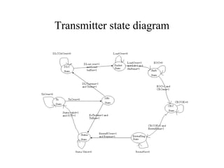
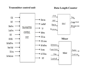
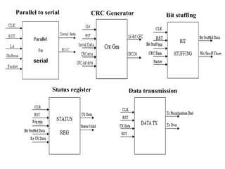
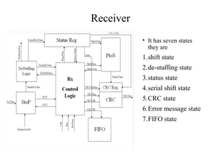
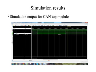
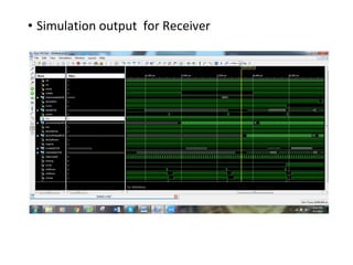
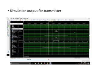
DESIGN AND
IMPLIMENTATION
OF CONTROLLER
AREA NETWORK
PROTOCOL
Contents
• Introduction
• Aim
• History
• CAN Principle
• Block diagram
• Transmitter
• Receiver
• Buffer
• Software and hardware required
• Results
• Advantages
• Applications
• Conclusion
Introduction
• The Controller Area Network (CAN) is a serial communication protocol,
which efficiently supports distributed real time control with high level of
security.
• The CAN protocol is an ISO standard (ISO 11898), which includes a
physical layer and a data-link layer of the OSI model.
• Of these two layers, Data link layer is the only layer, which can be
designed and implemented using VLSI technology.
• It can transmit from 0 to 8 bytes of information.
• The maximum data rate is 1 Mbs
Aim
• To understand and develop the architecture of Controller Area Network
which is used in data link layer of the OSI model and to simulate and
synthesize it at its functional level.
History
• In February of 1986, Robeggrt Bosch GmbH introduced the serial bus
system Controller Area Network (CAN) at the Society of Automotive
Engineers (SAE) congress.
• It was introduced as ‘Automotive Serial Controller Area Network’.
• Later Uwe Kiencke, Siegfried Dais and Martin Litschel introduced the
multi-master network protocol.
CAN Principle
• Data messages transmitted from any node on a CAN bus do not contain
addresses of either the transmitting node, or of any intended receiving
node. Instead, an identifier that is unique throughout the network labels
the content of the message.
• All other nodes on the network receive the message and each performs
an acceptance test on the identifier to determine if the message, and thus
its content, is relevant to that particular node.
• If the message is relevant, it will be processed; otherwise it is ignored
Block diagram
Transmitter
• It has 7 states they are:
1.DLC state
2.Packet state
3.Shift state
4.CRC state
5.Bit stuffing state
6.Status state
7.Transmission state
Transmitter state diagram
Transmitter control unit Data Length Counter
Mixer
serial
Parallel to serial CRC Generator Bit stuffing
Status register Data transmission
Receiver
• It has seven states
they are
1.shift state
2.de-stuffing state
3.status state
4.serial shift state
5.CRC state
6.Error message state
7.FIFO state
Receiver state diagram
Reciever control unit Serial to parallel
Destuffing
Status register
Parallel to serial
CRC Checker Error management logic
Buffer
• Transmit buffer and Receive buffers acts as interface to the micro
controller and the respective blocks (transmitter and receiver
respectively).
• Transmit buffer consists of two types of data namely arbitration of the
channel and user information, it takes the input from the micro
controller.
• Receive buffer consists of the user information and its output will be
taken by micro controller.
Software and Hardware required
• Software:
Xilinx ISE 14.7
• Hardware:
FPGA(SPARTAN-6)
Simulation results
• Simulation output for CAN top module
• Simulation output for Receiver
• Simulation output for transmitter
FPGA output
• FPGA output for receiver
• FPGA output for transmiter
Advantages
• Low-cost, lightweight network
• Broadcast communication
• Priority
• Error capabilities
Applications
• Can was first created for automotive use, so its most common
application is in-vehicle electronic networking.
• Railway applications such as streetcars, trams, undergrounds and long-
distance trains incorporate can.
• You can find can on different levels of the multiple networks.
• Can also has applications in aircraft with flight-state sensors, navigation
systems, and research pcs in the cockpit.
Conclusion
• All architectures are developed using Behavioral modeling in VHDL and
the functionality check for each block is performed successfully.
• The entire module in the architecture has been synthesized and
implemented using XILINX ISE 14.7 software.
• The required bitmap file used for JTAG programming of the device is
obtained successfully.

Controller area network protocol

  • 1.
  • 2.
    Contents • Introduction • Aim •History • CAN Principle • Block diagram • Transmitter • Receiver • Buffer • Software and hardware required • Results • Advantages • Applications • Conclusion
  • 3.
    Introduction • The ControllerArea Network (CAN) is a serial communication protocol, which efficiently supports distributed real time control with high level of security. • The CAN protocol is an ISO standard (ISO 11898), which includes a physical layer and a data-link layer of the OSI model. • Of these two layers, Data link layer is the only layer, which can be designed and implemented using VLSI technology. • It can transmit from 0 to 8 bytes of information. • The maximum data rate is 1 Mbs
  • 4.
    Aim • To understandand develop the architecture of Controller Area Network which is used in data link layer of the OSI model and to simulate and synthesize it at its functional level.
  • 5.
    History • In Februaryof 1986, Robeggrt Bosch GmbH introduced the serial bus system Controller Area Network (CAN) at the Society of Automotive Engineers (SAE) congress. • It was introduced as ‘Automotive Serial Controller Area Network’. • Later Uwe Kiencke, Siegfried Dais and Martin Litschel introduced the multi-master network protocol.
  • 6.
    CAN Principle • Datamessages transmitted from any node on a CAN bus do not contain addresses of either the transmitting node, or of any intended receiving node. Instead, an identifier that is unique throughout the network labels the content of the message. • All other nodes on the network receive the message and each performs an acceptance test on the identifier to determine if the message, and thus its content, is relevant to that particular node. • If the message is relevant, it will be processed; otherwise it is ignored
  • 7.
  • 8.
    Transmitter • It has7 states they are: 1.DLC state 2.Packet state 3.Shift state 4.CRC state 5.Bit stuffing state 6.Status state 7.Transmission state
  • 9.
  • 10.
    Transmitter control unitData Length Counter Mixer
  • 11.
    serial Parallel to serialCRC Generator Bit stuffing Status register Data transmission
  • 12.
    Receiver • It hasseven states they are 1.shift state 2.de-stuffing state 3.status state 4.serial shift state 5.CRC state 6.Error message state 7.FIFO state
  • 13.
  • 14.
    Reciever control unitSerial to parallel Destuffing
  • 15.
    Status register Parallel toserial CRC Checker Error management logic
  • 16.
    Buffer • Transmit bufferand Receive buffers acts as interface to the micro controller and the respective blocks (transmitter and receiver respectively). • Transmit buffer consists of two types of data namely arbitration of the channel and user information, it takes the input from the micro controller. • Receive buffer consists of the user information and its output will be taken by micro controller.
  • 17.
    Software and Hardwarerequired • Software: Xilinx ISE 14.7 • Hardware: FPGA(SPARTAN-6)
  • 18.
    Simulation results • Simulationoutput for CAN top module
  • 19.
  • 20.
    • Simulation outputfor transmitter
  • 21.
    FPGA output • FPGAoutput for receiver
  • 22.
    • FPGA outputfor transmiter
  • 23.
    Advantages • Low-cost, lightweightnetwork • Broadcast communication • Priority • Error capabilities
  • 24.
    Applications • Can wasfirst created for automotive use, so its most common application is in-vehicle electronic networking. • Railway applications such as streetcars, trams, undergrounds and long- distance trains incorporate can. • You can find can on different levels of the multiple networks. • Can also has applications in aircraft with flight-state sensors, navigation systems, and research pcs in the cockpit.
  • 25.
    Conclusion • All architecturesare developed using Behavioral modeling in VHDL and the functionality check for each block is performed successfully. • The entire module in the architecture has been synthesized and implemented using XILINX ISE 14.7 software. • The required bitmap file used for JTAG programming of the device is obtained successfully.