Ck35487490
•
0 likes•285 views

International Journal of Engineering Research and Applications (IJERA) is an open access online peer reviewed international journal that publishes research and review articles in the fields of Computer Science, Neural Networks, Electrical Engineering, Software Engineering, Information Technology, Mechanical Engineering, Chemical Engineering, Plastic Engineering, Food Technology, Textile Engineering, Nano Technology & science, Power Electronics, Electronics & Communication Engineering, Computational mathematics, Image processing, Civil Engineering, Structural Engineering, Environmental Engineering, VLSI Testing & Low Power VLSI Design etc.

Recommended
Recommended
More Related Content
What's hot
What's hot (20)
Viewers also liked
Viewers also liked (20)
Similar to Ck35487490
Similar to Ck35487490 (20)
Recently uploaded
Recently uploaded (20)
Ck35487490
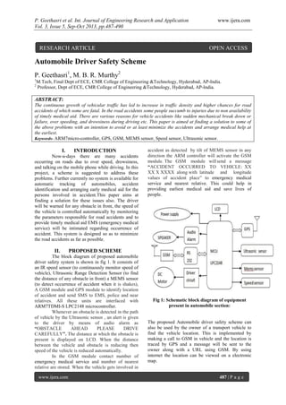
- 1. P. Geethasri et al. Int. Journal of Engineering Research and Application www.ijera.com Vol. 3, Issue 5, Sep-Oct 2013, pp.487-490 www.ijera.com 487 | P a g e Automobile Driver Safety Scheme P. Geethasri1 , M. B. R. Murthy2 1 M.Tech, Final Dept of ECE, CMR College of Engineering &Technology, Hyderabad, AP-India. 2 Professor, Dept of ECE, CMR College of Engineering &Technology, Hyderabad, AP-India. ABSTRACT: The continuous growth of vehicular traffic has led to increase in traffic density and higher chances for road accidents of which some are fatal. In the road accidents some people succumb to injuries due to non availability of timely medical aid. There are various reasons for vehicle accidents like sudden mechanical break down or failure, over speeding, and drowsiness during driving etc. This paper is aimed at finding a solution to some of the above problems with an intention to avoid or at least minimize the accidents and arrange medical help at the earliest. Keywords- ARM7micro-controller, GPS, GSM, MEMS sensor, Speed sensor, Ultrasonic sensor. I. INTRODUCTION Now-a-days there are many accidents occurring on roads due to over speed, drowsiness, and talking on the mobile phone while driving. In this project, a scheme is suggested to address these problems. Further currently no system is available for automatic tracking of automobiles, accident identification and arranging early medical aid for the persons involved in accident.This paper aims at finding a solution for these issues also. The driver will be warned for any obstacle in front, the speed of the vehicle is controlled automatically by monitoring the parameters responsible for road accidents and to provide timely medical aid EMS (emergency medical service) will be intimated regarding occurrence of accident. This system is designed so as to minimize the road accidents as far as possible. II. PROPOSED SCHEME The block diagram of proposed automobile driver safety system is shown in fig 1. It consists of an IR speed sensor (to continuously monitor speed of vehicle), Ultrasonic Range Detection Sensor (to find the distance of any obstacle in front) a MEMS sensor (to detect occurrence of accident when it is shakes), A GSM module and GPS module to identify location of accident and send SMS to EMS, police and near relatives. All these units are interfaced with ARM7TDMI-S LPC2148 microcontroller. Whenever an obstacle is detected in the path of vehicle by the Ultrasonic sensor , an alert is given to the driver by means of audio alarm as “OBSTACLE AHEAD PLEASE DRIVE CAREFULLY”. The distance at which the obstacle is present is displayed on LCD. When the distance between the vehicle and obstacle is reducing then speed of the vehicle is reduced automatically. In the GSM module contact number of emergency medical service and number of nearest relative are stored. When the vehicle gets involved in accident as detected by tilt of MEMS sensor in any direction the ARM controller will activate the GSM module. The GSM module willsend a message “ACCIDENT OCCURRED TO VEHICLE: XX XX X XXXX along with latitude and longitude values of accident place” to emergency medical service and nearest relative. This could help in providing earliest medical aid and save lives of people. Fig 1: Schematic block diagram of equipment present in automobile section: The proposed Automobile driver safety scheme can also be used by the owner of a transport vehicle to find the vehicle location. This is implemented by making a call to GSM in vehicle and the location is traced by GPS and a message will be sent to the owner along with a URL using GSM. By using internet the location can be viewed on a electronic map. RESEARCH ARTICLE OPEN ACCESS
- 2. P. Geethasri et al. Int. Journal of Engineering Research and Application www.ijera.com Vol. 3, Issue 5, Sep-Oct 2013, pp.487-490 www.ijera.com 488 | P a g e III. HARDWARE DESCRIPTION 3.1. ARM7 The LPC2148 microcontrollers are based on a 32/16 bit ARM7TDMI-S CPU with real-time emulation and embedded trace support, that combines the microcontroller with embedded high speed flash memory ranging from 32 kB to 512 kB. The entire design is controlled with a written program stored into its ROM. The on chip features of this controller reduce the system cost and better solution for network applications. Fig 2: LPC2148 Microcontroller 3.2. SPEED SENSOR This circuit is designed to monitor the speed of the motor. The holes type pulley is attached in the motor shaft. The pulley is rotated across the USLOT. The USLOT consists of IR transmitter and receiver. Infrared transmitter is one type of LED which emits infrared rays generally called as IR transmitter. Similarly IR Receiver is used to receive the IR rays transmitted by the IR transmitter. Both IR Transmitter and receiver should be placed straight line to each other. When supply is ON, the IR transmitter LED is conducting. It passes the IR rays to the receiver. When motor is rotating, the pulley attached in the shaft also rotating so, it interprets the IR rays between transmitter and receiver. Hence depending on the motor speed zero to 5v square pulse is generating at the output which is given to microcontroller in order to count the pulse. This pulse rate is equal to the speed of the motor. Fig 3: Speed sensor 3.3.ULTRASONIC SENSOR Ultrasonic Range Detection Sensor, it's an IC that works by sending an ultrasound pulse at around 40Khz. We need to supply a short 10ús pulse to the trigger input to start the ranging. The module will send out an 8 cycle burst of ultrasound at 40khz and raise its echo line high. It then listens for an echo and as soon as it detects one it lowers the echo line again. The echo line is therefore a pulse whose width is proportional to the distance to the object. By timing the pulse it is possible to calculate the range in inches/centimeters or anything else. Fig 3: Ultrasonic Sensor 3.4ACCIDENT DETECTION MODULE(MEMS) An MEMS accelerometer measures acceleration (change in speed) of anything that it's mounted on. Single axis accelerometers measure acceleration in only one direction. Dual-axis accelerometers, which are the most common, measure acceleration in two directions, perpendicular to each other. Three-axis accelerometers measure acceleration in three directions. Accelerometers are very handy for measuring the orientation of an object relative to the earth, because gravity causes all objects to accelerate towards the earth. A two-axis accelerometer can be used to measure how level an object is with a three-axis accelerometer, you can measure an object's acceleration in every direction. In my paper when the MEMS sensor is shaken it assumes that the accident occurred. 3.5.GPS MODULE The Global Positioning System (GPS) is a satellite based navigation system that sends and receives radio signals. The basis of the GPS technology is a set of 24 satellites that are continuously orbiting the earth. These satellites are equipped with atomic clocks and send out radio signals as to the exact time and their location. These radio signals from the satellites are picked up by the GPS receiver. Once the GPS receiver locks on to four or more of these satellites, it can triangulate its location from the known positions of the satellites. In my paper when accident occurs the GPS receiver finds the latitude and longitude values so that the accident location is find out and the victims can be rescued. Fig 4: Global Positioning System 3.6.GSM MODULE GSM (Global System for Mobile communications) is an open, digital cellular
- 3. P. Geethasri et al. Int. Journal of Engineering Research and Application www.ijera.com Vol. 3, Issue 5, Sep-Oct 2013, pp.487-490 www.ijera.com 489 | P a g e technology used for transmitting mobile voice and data services. GSM uses a variation of Time Division Multiple Access (TDMA) and is the most widely used of the three digital wireless telephone technologies (TDMA, GSM, and CDMA. It operates at either the 900 MHz or 1,800 MHz frequency band. It supports voice calls and data transfer speeds of up to 9.6 kbit/s, together with the transmission of SMS (Short Message Service). In my paper GSM modem is used at two points. One is when the driver exceeds speed limits at speed limit zone, the vehicle and the speed limit zone details are sent to the traffic police system using GSM modem. Other is when accident occurs location values are taken from GPS receiver and sent through GSM modem. 3.7.DC MOTOR A DC motor consists of a rotor and a permanent magnetic field stator. Who’s maintained by using either permanent magnets or electromagnetic windings. DC motors are most commonly used in variable speed and torque applications. IV. SOFTWARE DESIGN The different software’s used to develop the system are 4.1. Embedded C Source code is written in C .Programming in C makes the embedded systems more reliable hence code written for a specific microcontroller can easily be transferred to systems using different micro controllers. It can be reused, easy to maintain and easy to debug and extend. Also writing in C simplifies code development for large projects. It is easier to modify and update. 4.2. Flash Magic Flash Magic is a tool which is used to program hex code in EEPROM of micro-controller. It is a freeware tool. This supports the micro-controller of Philips and NXP. To burn a hex code into those controllers flash magic is used, which supports ISP (in system programming) feature. 4.3. Keil µVision IDE The µVision IDE from Keil combines project management, source code editing, program debugging, and complete simulation in one powerful environment. The µVision development platform is easy-to-use and helps to quickly create embedded programs that work. The µVision editor and debugger are integrated in a single application that provides a seamless embedded project development environment. V. RESULTS AND DISCUSSION The proposed system was tested and performance was satisfactory and the results are presented below: The ultrasonic sensor detects the obstacle ahead and gives the distance at which the obstacle is present and the speed sensor gives the speed at which the vehicle is moving . This is shown in Fig 5(a) When there is a tilt in MEMS it is recognized as accident has occurred and message is sent with latitude and longitude values. Fig 5(b) gives position information. The received message will be as shown in Fig 6 Accident has occurred to vehicle xxxx and a URL is sent. By clicking on the URL the location can be traced. Fig:5(a) Fig:5(b) Fig 5: (a) Display of speed and distance of obstacle (b) message about accident with Latitude & longitude values
- 4. P. Geethasri et al. Int. Journal of Engineering Research and Application www.ijera.com Vol. 3, Issue 5, Sep-Oct 2013, pp.487-490 www.ijera.com 490 | P a g e . Fig 6: received Message with URL and by clicking URL location can be traced VI. CONCLUSIONS An Automobile Driver Safety Scheme is developed that helps in preventing accidents to a large extent. Further in case of any accident medical care is provided very fast. The scheme can also be used by the owner of the transport vehicles for tracking his vehicles REFERENCE [1].2009 FARS/NASS GES Standardization Fatality Analysis Reporting System PARS). National Highway Traffic Safety Administration, NHTSA- US department of transportation report- 2010 [2].Hong hong Wang and Shuhua Xu, “An Automatic Supervisory Control System Based Real-Time Technology and GSM or GPRS Network- WiCOM '08. 4th International Conference on Wireless Communications, Networking and Mobile Computing, 2008. [3].Design of Intelligent Transport Related Issue System Based on ARM7, V.Dhanaraj, et al, International Journal of research in Computer & Communication Technology, IJRCCT,ISSN 2278- 5841, Vol 1, Issue 4, September 2012 [4]. Vehicle Speed Limit Alerting and Crash Detection System at Various Zones, International Journal of Latest Trends in Engineering and Technology (IJLTET) ISSN: 2278-621X Vol. 2 Issue 1 January 2013 [5] Book: “ARM System On-Chip Architecture”,-second edition by Steve Furber. .