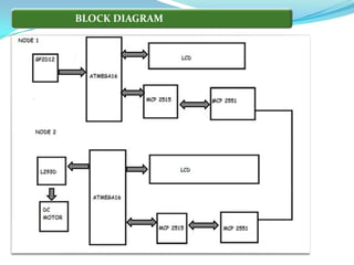
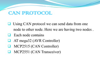
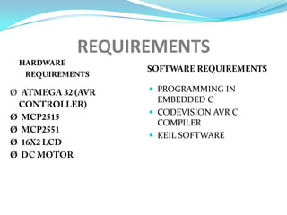
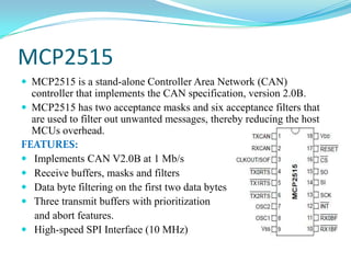
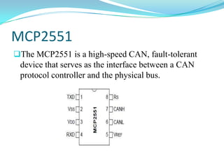
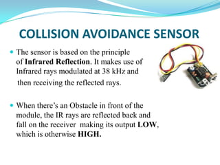
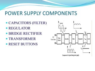
This project CAN BASED COLLISION
AVOIDANCE SYSTEM(CAN) is intended for
secure and smooth journey.
 If the driver himself is not concentrating on
driving or any other parameters, which may cause
damage to vehicle as well a life, this intelligent car/
vehicle warn the driver regarding the danger ahead.
 Due to the driver’s distraction, a serious collision accident
may occur if the driver can not react in time to brake.
 For the front-end collision avoidance subsystem, Collision
avoidance sensor is adopted to measure the distance with
respect to the previous car.
 For rear-end collision avoidance subsystem, the currently
available collision avoidance sensors for vehicles are
adopted for approaching cars with relatively low speed.
power train management system
 antilock braking system (ABS)
 acceleration skid control (ASC) system, etc,
 the functionality and wiring of these electric
control units (ECU) are getting more
complicated. Therefore, it is of great concern to
upgrade the traditional wire harness to a smart
car network.
The Controller Area Network (CAN) is a
Serial, Asynchronous, Multi-master
communication protocol for connecting
electronic control modules.
The CAN Network is a Peer to Peer Network
consisting of different nodes.
FEATURES
OF CAN
 Low cost
 Easy to implement
 peer to peer Network
 powerful Error Checking
 Higher Transmission Rates 1MBitps
 high immunity to external noise signals
 Today the CAN bus is also used as a field bus in general
automation environments
BLOCK DIAGRAM
CAN PROTOCOL
 Using CAN protocol we can send data from one
node to other node. Here we are having two nodes .
 Each node contains
 AT mega32 (AVR Controller)
 MCP2515 (CAN Controller)
 MCP2551 (CAN Transceiver)
CAN PROTOCOL
 In first node we are interfacing Collision avoidance
sensor to find the object.
 Second node contains DC motor
 If any object is found in front of Collision avoidance
sensor in node1, DC motor in node2 stops running by
using CAN protocol.
 For this two different application programs in AVR
studio are to be developed.
 An Embedded system is defined as, the
software code to interact directly with that
particular hardware what we built for a
particular/specific application.
 Software is used for providing features and
flexibility, Hardware
(Processors, ASICs, Memory) is used for
Performance & sometimes security.
Based on functionality and performance
embedded systems categorized as 4 types:
 1. Stand alone embedded systems
 2. Real time embedded systems
 3. Networked information appliances
 4. Mobile devices
REQUIREMENTS
HARDWARE
REQUIREMENTS
SOFTWARE REQUIREMENTS
Ø  PROGRAMMING IN
EMBEDDED C
 CODEVISION AVR C
COMPILER
 KEIL SOFTWARE
AVR CONTROLLER
 The ATmega32 is a low-power CMOS 8-bit
microcontroller based on the AVR enhanced RISC
architecture. Its features are:
 High-performance, Low-power AVR 8-bit
Microcontroller
 Advanced RISC Architecture
 131 Powerful Instructions – Most Single-clock Cycle
Execution
32 x 8 General Purpose Working Registers
 High Endurance Non-volatile Memory segments
On-chip Analog Comparator
 Power-on Reset and Programmable Brown-out Detection
 Internal Calibrated RC Oscillator
 Six Sleep Modes: Idle, ADC Noise Reduction, Power-save,
Power-down, Standby and Extended Standby
SPEED GRADES:
0 - 8 MHz for ATmega32L
0 - 16 MHz for ATmega32
PIN DESCRIPTION OF AVR
 Port A (PA7-PA0) :Port A serves as the analog
inputs to the A/D Converter.
 Port B (PB7-PB0): Port B is an 8-bit bi-directional
I/O port with internal pull-up resistors (selected for
each bit).
 Port C (PC7-PC0): Port C is an 8-bit bi-directional
I/O port with internal pull-up resistors.
 XTAL1: Input to the inverting Oscillator amplifier
and input to the internal clock operating circuit.
 XTAL2: Output from the inverting Oscillator
amplifier.
MCP2515
 MCP2515 is a stand-alone Controller Area Network (CAN)
controller that implements the CAN specification, version 2.0B.
 MCP2515 has two acceptance masks and six acceptance filters that
are used to filter out unwanted messages, thereby reducing the host
MCUs overhead.
FEATURES:
 Implements CAN V2.0B at 1 Mb/s
 Receive buffers, masks and filters
 Data byte filtering on the first two data bytes
 Three transmit buffers with prioritization
and abort features.
 High-speed SPI Interface (10 MHz)
MCP2551
The MCP2551 is a high-speed CAN, fault-tolerant
device that serves as the interface between a CAN
protocol controller and the physical bus.
FEATURES OF MCP2551
 Protection against damage due to short-circuit
conditions (positive or negative battery voltage)
 Protection against high-voltage transients
 Automatic thermal shutdown protection
 Up to 112 nodes can be connected
 High noise immunity due to differential bus
Implementation
 Liquid crystal displays (LCDs)
have materials which combine
the properties of both liquids
and crystals.
 They have a temperature range within which the
molecules are almost as mobile as they would be in a
liquid, but are grouped together in an ordered form
similar to a crystal.
 Since the LCD’s consume less power, they are compatible
with low power electronic circuits and can be powered
for long durations.
 The sensor is based on the principle
of Infrared Reflection. It makes use of
Infrared rays modulated at 38 kHz and
then receiving the reflected rays.
 When there’s an Obstacle in front of the
module, the IR rays are reflected back and
fall on the receiver making its output LOW,
which is otherwise HIGH.
COLLISION AVOIDANCE SENSOR
POWER SUPPLY COMPONENTS
 CAPACITORS (FILTER)
 REGULATOR
 BRIDGE RECTIFIER
 TRANSFORMER
 RESET BUTTONS
THANK Q
CAN BASED COLLISION AVOIDANCE SYSTEM FOR AUTOMOBILES

CAN BASED COLLISION AVOIDANCE SYSTEM FOR AUTOMOBILES

  • 2.
    This project CANBASED COLLISION AVOIDANCE SYSTEM(CAN) is intended for secure and smooth journey.  If the driver himself is not concentrating on driving or any other parameters, which may cause damage to vehicle as well a life, this intelligent car/ vehicle warn the driver regarding the danger ahead.
  • 3.
     Due tothe driver’s distraction, a serious collision accident may occur if the driver can not react in time to brake.  For the front-end collision avoidance subsystem, Collision avoidance sensor is adopted to measure the distance with respect to the previous car.  For rear-end collision avoidance subsystem, the currently available collision avoidance sensors for vehicles are adopted for approaching cars with relatively low speed.
  • 4.
    power train managementsystem  antilock braking system (ABS)  acceleration skid control (ASC) system, etc,  the functionality and wiring of these electric control units (ECU) are getting more complicated. Therefore, it is of great concern to upgrade the traditional wire harness to a smart car network.
  • 5.
    The Controller AreaNetwork (CAN) is a Serial, Asynchronous, Multi-master communication protocol for connecting electronic control modules. The CAN Network is a Peer to Peer Network consisting of different nodes.
  • 6.
    FEATURES OF CAN  Lowcost  Easy to implement  peer to peer Network  powerful Error Checking  Higher Transmission Rates 1MBitps  high immunity to external noise signals  Today the CAN bus is also used as a field bus in general automation environments
  • 7.
  • 8.
    CAN PROTOCOL  UsingCAN protocol we can send data from one node to other node. Here we are having two nodes .  Each node contains  AT mega32 (AVR Controller)  MCP2515 (CAN Controller)  MCP2551 (CAN Transceiver)
  • 9.
    CAN PROTOCOL  Infirst node we are interfacing Collision avoidance sensor to find the object.  Second node contains DC motor  If any object is found in front of Collision avoidance sensor in node1, DC motor in node2 stops running by using CAN protocol.  For this two different application programs in AVR studio are to be developed.
  • 10.
     An Embeddedsystem is defined as, the software code to interact directly with that particular hardware what we built for a particular/specific application.  Software is used for providing features and flexibility, Hardware (Processors, ASICs, Memory) is used for Performance & sometimes security.
  • 11.
    Based on functionalityand performance embedded systems categorized as 4 types:  1. Stand alone embedded systems  2. Real time embedded systems  3. Networked information appliances  4. Mobile devices
  • 12.
    REQUIREMENTS HARDWARE REQUIREMENTS SOFTWARE REQUIREMENTS Ø PROGRAMMING IN EMBEDDED C  CODEVISION AVR C COMPILER  KEIL SOFTWARE
  • 13.
    AVR CONTROLLER  TheATmega32 is a low-power CMOS 8-bit microcontroller based on the AVR enhanced RISC architecture. Its features are:  High-performance, Low-power AVR 8-bit Microcontroller  Advanced RISC Architecture  131 Powerful Instructions – Most Single-clock Cycle Execution 32 x 8 General Purpose Working Registers
  • 14.
     High EnduranceNon-volatile Memory segments On-chip Analog Comparator  Power-on Reset and Programmable Brown-out Detection  Internal Calibrated RC Oscillator  Six Sleep Modes: Idle, ADC Noise Reduction, Power-save, Power-down, Standby and Extended Standby SPEED GRADES: 0 - 8 MHz for ATmega32L 0 - 16 MHz for ATmega32
  • 15.
  • 16.
     Port A(PA7-PA0) :Port A serves as the analog inputs to the A/D Converter.  Port B (PB7-PB0): Port B is an 8-bit bi-directional I/O port with internal pull-up resistors (selected for each bit).  Port C (PC7-PC0): Port C is an 8-bit bi-directional I/O port with internal pull-up resistors.  XTAL1: Input to the inverting Oscillator amplifier and input to the internal clock operating circuit.  XTAL2: Output from the inverting Oscillator amplifier.
  • 17.
    MCP2515  MCP2515 isa stand-alone Controller Area Network (CAN) controller that implements the CAN specification, version 2.0B.  MCP2515 has two acceptance masks and six acceptance filters that are used to filter out unwanted messages, thereby reducing the host MCUs overhead. FEATURES:  Implements CAN V2.0B at 1 Mb/s  Receive buffers, masks and filters  Data byte filtering on the first two data bytes  Three transmit buffers with prioritization and abort features.  High-speed SPI Interface (10 MHz)
  • 18.
    MCP2551 The MCP2551 isa high-speed CAN, fault-tolerant device that serves as the interface between a CAN protocol controller and the physical bus.
  • 19.
    FEATURES OF MCP2551 Protection against damage due to short-circuit conditions (positive or negative battery voltage)  Protection against high-voltage transients  Automatic thermal shutdown protection  Up to 112 nodes can be connected  High noise immunity due to differential bus Implementation
  • 20.
     Liquid crystaldisplays (LCDs) have materials which combine the properties of both liquids and crystals.  They have a temperature range within which the molecules are almost as mobile as they would be in a liquid, but are grouped together in an ordered form similar to a crystal.  Since the LCD’s consume less power, they are compatible with low power electronic circuits and can be powered for long durations.
  • 21.
     The sensoris based on the principle of Infrared Reflection. It makes use of Infrared rays modulated at 38 kHz and then receiving the reflected rays.  When there’s an Obstacle in front of the module, the IR rays are reflected back and fall on the receiver making its output LOW, which is otherwise HIGH. COLLISION AVOIDANCE SENSOR
  • 22.
    POWER SUPPLY COMPONENTS CAPACITORS (FILTER)  REGULATOR  BRIDGE RECTIFIER  TRANSFORMER  RESET BUTTONS
  • 23.