
Downloaded 39 times
![International Journal of Engineering Inventions
ISSN: 2278-7461, www.ijeijournal.com
Volume 1, Issue 7(October2012) PP: 06-12
BLACK BOX FOR VEHICLES
P. Ajay Kumar Reddy 1, P.Dileep Kumar 2, K. Bhaskar reddy3, E.Venkataramana 4,
M.Chandra sekhar Reddy 5
1,2,3,4,5
(Assistant Professor, Department of ECE, Kuppam Engineering College/JNTUA/INDIA)
Abstract:––The main purpose of the paper is to develop a prototype of Black Box For vehicle diagnosis that can be installed
into any vehicle. This prototype can be designed with minimum number of circuits. This can contribute to construct safer
vehicles, improving the treatment for crash victims, helping insurance companies with their vehicle crash investigations, and
enhancing road status in order to decrease the death rate.
Keywords:––Vehicle, Black Box, Microcontroller, Computer Interface
I. INTRODUCTION
According to the World Health Organization, more than a million people in the world die each year because of
transportation-related accidents [1]. In order to react to this situation, the black box system draws the first step to solve
problem. Like flight data recorders in aircraft, "Black Box” technology can now play a key role in motor vehicle crash
investigations [4]. A significant number of vehicles currently on the roads contain electronic systems that record in the event
of a crash. That is why it is so important to have recorders that objectively track what goes on in vehicles before, during and
after a crash as a complement to the was used. Subjective input that is taken usually from victims, eye witnesses and police
reports. This system is mainly committed to two sections. The first one is how to detect and collect the information from the
vehicle. The second is how to present the data to the user in a simplified way. To implement the first section many
components and various types of sensors are used. While the second section was implementing by using the Embedded C
programming. This programming helps in not only recording the data but also retrieving the data from microcontroller
memory to an LCD to display it. In order to know which type of sensors to be installed into the vehicle various types of
research are done and following ones are considered as the most important data that is needed after the accident: Belt status,
Break status, Lane detection and CAN Failures. In this section we describe in section II the hard ware resources and in
section III the software resources followed by the conclusion in section IV.
II. HARDWARE RESOURCES
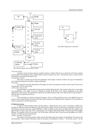
The hardware part consists of the components and the sensors used in the black box system. This part mainly
collects the status of the sensors and stores it into the micro controller‘s EEPROM.
A. Sensors.
1) Proximity Sensor
A proximity sensor is used to detect the lanes in which the vehicle is travelling. A proximity sensor is a sensor able
to detect the presence of nearby objects without any physical contact. A proximity sensor often emits an electromagnetic or
electrostatic field, or a beam of electromagnetic radiation (infrared, for instance), and looks for changes in the field or return
signal.
2) Ultrasonic sensor
The ultrasonic sensor is to measure the minimum distance in front of the vehicle Ultrasonic sensors work on a
principle similar to radar or sonar which evaluate attributes of a target by interpreting the echoes from radio or sound waves
respectively. Ultrasonic sensors generate high frequency sound waves and evaluate the echo which is received back by the
sensor.
ISSN: 2278-7461 www.ijeijournal.com P a g e |6](https://image.slidesharecdn.com/b0170612-121107055328-phpapp01/85/International-Journal-of-Engineering-Inventions-IJEI-1-320.jpg)
![International Journal of Engineering Inventions
ISSN: 2278-7461, www.ijeijournal.com
Volume 1, Issue 7(October2012) PP: 06-12
BLACK BOX FOR VEHICLES
P. Ajay Kumar Reddy 1, P.Dileep Kumar 2, K. Bhaskar reddy3, E.Venkataramana 4,
M.Chandra sekhar Reddy 5
1,2,3,4,5
(Assistant Professor, Department of ECE, Kuppam Engineering College/JNTUA/INDIA)
Abstract:––The main purpose of the paper is to develop a prototype of Black Box For vehicle diagnosis that can be installed
into any vehicle. This prototype can be designed with minimum number of circuits. This can contribute to construct safer
vehicles, improving the treatment for crash victims, helping insurance companies with their vehicle crash investigations, and
enhancing road status in order to decrease the death rate.
Keywords:––Vehicle, Black Box, Microcontroller, Computer Interface
I. INTRODUCTION
According to the World Health Organization, more than a million people in the world die each year because of
transportation-related accidents [1]. In order to react to this situation, the black box system draws the first step to solve
problem. Like flight data recorders in aircraft, "Black Box” technology can now play a key role in motor vehicle crash
investigations [4]. A significant number of vehicles currently on the roads contain electronic systems that record in the event
of a crash. That is why it is so important to have recorders that objectively track what goes on in vehicles before, during and
after a crash as a complement to the was used. Subjective input that is taken usually from victims, eye witnesses and police
reports. This system is mainly committed to two sections. The first one is how to detect and collect the information from the
vehicle. The second is how to present the data to the user in a simplified way. To implement the first section many
components and various types of sensors are used. While the second section was implementing by using the Embedded C
programming. This programming helps in not only recording the data but also retrieving the data from microcontroller
memory to an LCD to display it. In order to know which type of sensors to be installed into the vehicle various types of
research are done and following ones are considered as the most important data that is needed after the accident: Belt status,
Break status, Lane detection and CAN Failures. In this section we describe in section II the hard ware resources and in
section III the software resources followed by the conclusion in section IV.
II. HARDWARE RESOURCES
The hardware part consists of the components and the sensors used in the black box system. This part mainly
collects the status of the sensors and stores it into the micro controller‘s EEPROM.
A. Sensors.
1) Proximity Sensor
A proximity sensor is used to detect the lanes in which the vehicle is travelling. A proximity sensor is a sensor able
to detect the presence of nearby objects without any physical contact. A proximity sensor often emits an electromagnetic or
electrostatic field, or a beam of electromagnetic radiation (infrared, for instance), and looks for changes in the field or return
signal.
2) Ultrasonic sensor
The ultrasonic sensor is to measure the minimum distance in front of the vehicle Ultrasonic sensors work on a
principle similar to radar or sonar which evaluate attributes of a target by interpreting the echoes from radio or sound waves
respectively. Ultrasonic sensors generate high frequency sound waves and evaluate the echo which is received back by the
sensor.
ISSN: 2278-7461 www.ijeijournal.com P a g e |6](https://image.slidesharecdn.com/b0170612-121107055328-phpapp01/75/International-Journal-of-Engineering-Inventions-IJEI-1-2048.jpg)
![Black Box for Vehicles
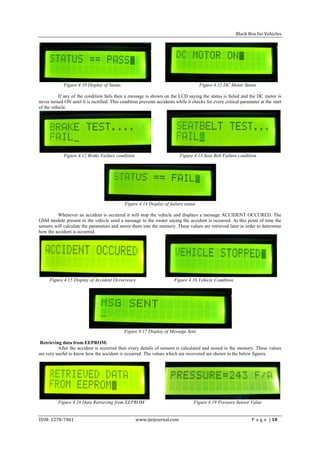
Figure 4.20 Temperature Sensor Value Figure 4.21 Ultrasonic sensors Value
Figure 4.22 Proximity Sensor Value Figure 4.23 Seat Belt statuses
Figure 4.24 Messages from Black Box
The message is displayed in the phone after the accident is occurred to the vehicle. This is sent to the emergency
numbers by the GSM module which is fixed in the vehicle.
VI. FUTURE ENHANCEMENTS
Use of GPS module with this system will be helpful in finding the accident location and take quick rescue
operations. We can enhance the present system to check other parameters like fuel level, tyre pressure and working of
headlights before starting the vehicle .Many other critical parameters can be read and stored in the memory.
Another useful add-on to the present system could be cameras on front and backsides which keep recording live images and
storing them in memory. This video data would be much useful for accident investigation.
ACKNOWLEDGMENT
This work is supported by Kuppam Engineering College and thanks for valuable references provided by the
authors. Any opinions, findings, and conclusions or recommendations expressed in this material are those of the authors and
do not necessarily reflect their views
I would also like to express my gratitude to all other members of the faculty of Electronics and Communication Engineering
department for their cooperation.
I also express my gratitude to my parents for the support they have given me so far. I would like to thank my dear friends,
for their kind-hearted cooperation and encouragement
REFERENCES
1. G. Hayes, F. Blosser, "Motor Vehicle Crashes Claim More than a Million Accident Position Lives Worldwide",
CDC Injury Center Media Relations, Press Release, At The Ajkident April, 2004.
2. http://www.airbagcrash.com (General Motor Event Data Recorders)
3. Thomas K. Kowalick, "Black Boxes: Event Data Recorders", MICAH,summer 2005.
4. K. Kowalick, "Black Boxes: Event Data Recorder Rulemaking for Automobiles", MICAH, summer 2006.
5. Thomas K. Kowalick, "Fatal Exit: The Automotive Black Box Debate", Wiley, IEEE Press, Feb. 2005.
6. Available [online]: www.alldatasheet.com
7. M. A. Mazidi, J. C. Mazidi, R. D. Mckinaly, the 8051 Microcontroller and Embedded Systems, Pearson Education,
2006.
8. http://www.keil.com
9. http://www.microcontroller.com/EmbeddedSystems.asp?c=11
10. http://www.scienceprog.com/arm7-lpc2129-mini-board/
ISSN: 2278-7461 www.ijeijournal.com P a g e | 11](https://image.slidesharecdn.com/b0170612-121107055328-phpapp01/85/International-Journal-of-Engineering-Inventions-IJEI-6-320.jpg)
The document proposes designing a black box device for vehicles that can record critical safety data like seatbelt use, braking, and lane position during accidents to help investigate crashes. It describes the hardware components like sensors and microcontrollers used to collect and store data, and the software used to program the microcontroller and interface with a computer. Experimental results demonstrate the black box system's ability to monitor vehicle operations and record sensor values during simulated accidents.


![[IJET-V1I4P10] Authers :EiEi Thwe, Theingi](https://cdn.slidesharecdn.com/ss_thumbnails/ijet-v1i4p10-150810164804-lva1-app6892-thumbnail.jpg?width=640&height=640&fit=bounds)


