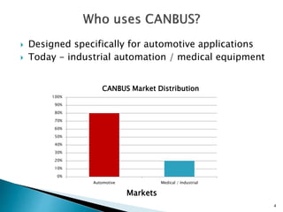
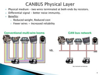
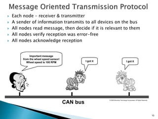
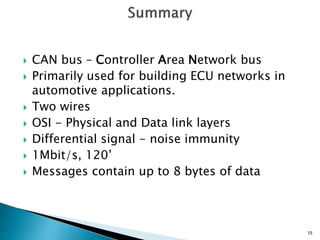
Introduction to
CANBUS
Presented by: Marek Hajek
1
1. CANBUS Introduction
 What is CANBUS?
 Who uses CANBUS?
 CANBUS history
 CANBUS timeline
2. CANBUS Characteristics
 OSI Model
 Physical Layer
 Transmission Characteristics
3. Message Oriented Communication
4. Message Format
5. Bus Arbitration
2
CANBUS or CAN bus – Controller Area Network bus
An automotive serial bus system developed to satisfy
the following requirements:
 Network multiple microcontrollers with 1 pair of wires.
 Allow microcontrollers communicate with each other.
 High speed, real-time communication.
 Provide noise immunity in an electrically noisy environment.
 Low cost
3
 Designed specifically for automotive applications
 Today - industrial automation / medical equipment
4
0%
10%
20%
30%
40%
50%
60%
70%
80%
90%
100%
Automotive Medical / Industrial
Markets
CANBUS Market Distribution
5
 First idea - The idea of CAN was first conceived by
engineers at Robert Bosch Gmbh in Germany in the
early 1980s.
 Early focus - develop a communication system
between a number of ECUs (electronic control
units).
 New standard - none of the communication
protocols at that time met the specific
requirements for speed and reliability so the
engineers developed their own standard.
6
 1983 : First CANBUS project at Bosch
 1986 : CAN protocol introduced
 1987 : First CAN controller chips sold
 1991 : CAN 2.0A specification published
 1992 : Mercedes-Benz used CAN network
 1993 : ISO 11898 standard
 1995 : ISO 11898 amendment
 Present : The majority of vehicles use CAN bus.
 CAN is a closed network
◦ – no need for security, sessions or logins.
◦ - no user interface requirements.
 Physical and Data Link layers in silicon.
7
8
Conventional multi-wire looms CAN bus network
 Physical medium – two wires terminated at both ends by resistors.
 Differential signal - better noise immunity.
 Benefits:
 Reduced weight, Reduced cost
 Fewer wires = Increased reliability
vs.
http://canbuskit.com/what.php
9
 Up to 1 Mbit/sec.
 Common baud rates: 1 MHz, 500 KHz and 125 KHz
 All nodes – same baud rate
 Max length:120’ to 15000’ (rate dependent)
© esd electronics, Inc. • 525 Bernardston Road • Greenfield, MA 01301
10
 Each node – receiver & transmitter
 A sender of information transmits to all devices on the bus
 All nodes read message, then decide if it is relevant to them
 All nodes verify reception was error-free
 All nodes acknowledge reception
CAN bus
© 2005 Microchip Technology Incorporated. All Rights Reserved.
11
 Each message has an ID, Data and overhead.
 Data –8 bytes max
 Overhead – start, end, CRC, ACK
12
13
 Arbitration – needed when multiple nodes try to transmit at the
same time
 Only one transmitter is allowed to transmit at a time.
 A node waits for bus to become idle
 Nodes with more important messages continue transmitting
CAN bus
© 2005 Microchip Technology Incorporated. All Rights Reserved.
14
 Message importance is encoded in message ID.
Lower value = More important
 As a node transmits each bit, it verifies that it sees
the same bit value on the bus that it transmitted.
 A “0” on the bus wins over a “1” on the bus.
 Losing node stops transmitting, winner continues.
 CAN bus – Controller Area Network bus
 Primarily used for building ECU networks in
automotive applications.
 Two wires
 OSI - Physical and Data link layers
 Differential signal - noise immunity
 1Mbit/s, 120’
 Messages contain up to 8 bytes of data
15
 Marek Hajek
16
A “0” (low voltage) on the bus by 1 node
wins over a “1” (high voltage) on the bus.
17
18

Canbus

  • 1.
  • 2.
    1. CANBUS Introduction What is CANBUS?  Who uses CANBUS?  CANBUS history  CANBUS timeline 2. CANBUS Characteristics  OSI Model  Physical Layer  Transmission Characteristics 3. Message Oriented Communication 4. Message Format 5. Bus Arbitration 2
  • 3.
    CANBUS or CANbus – Controller Area Network bus An automotive serial bus system developed to satisfy the following requirements:  Network multiple microcontrollers with 1 pair of wires.  Allow microcontrollers communicate with each other.  High speed, real-time communication.  Provide noise immunity in an electrically noisy environment.  Low cost 3
  • 4.
     Designed specificallyfor automotive applications  Today - industrial automation / medical equipment 4 0% 10% 20% 30% 40% 50% 60% 70% 80% 90% 100% Automotive Medical / Industrial Markets CANBUS Market Distribution
  • 5.
    5  First idea- The idea of CAN was first conceived by engineers at Robert Bosch Gmbh in Germany in the early 1980s.  Early focus - develop a communication system between a number of ECUs (electronic control units).  New standard - none of the communication protocols at that time met the specific requirements for speed and reliability so the engineers developed their own standard.
  • 6.
    6  1983 :First CANBUS project at Bosch  1986 : CAN protocol introduced  1987 : First CAN controller chips sold  1991 : CAN 2.0A specification published  1992 : Mercedes-Benz used CAN network  1993 : ISO 11898 standard  1995 : ISO 11898 amendment  Present : The majority of vehicles use CAN bus.
  • 7.
     CAN isa closed network ◦ – no need for security, sessions or logins. ◦ - no user interface requirements.  Physical and Data Link layers in silicon. 7
  • 8.
    8 Conventional multi-wire loomsCAN bus network  Physical medium – two wires terminated at both ends by resistors.  Differential signal - better noise immunity.  Benefits:  Reduced weight, Reduced cost  Fewer wires = Increased reliability vs. http://canbuskit.com/what.php
  • 9.
    9  Up to1 Mbit/sec.  Common baud rates: 1 MHz, 500 KHz and 125 KHz  All nodes – same baud rate  Max length:120’ to 15000’ (rate dependent) © esd electronics, Inc. • 525 Bernardston Road • Greenfield, MA 01301
  • 10.
    10  Each node– receiver & transmitter  A sender of information transmits to all devices on the bus  All nodes read message, then decide if it is relevant to them  All nodes verify reception was error-free  All nodes acknowledge reception CAN bus © 2005 Microchip Technology Incorporated. All Rights Reserved.
  • 11.
    11  Each messagehas an ID, Data and overhead.  Data –8 bytes max  Overhead – start, end, CRC, ACK
  • 12.
  • 13.
    13  Arbitration –needed when multiple nodes try to transmit at the same time  Only one transmitter is allowed to transmit at a time.  A node waits for bus to become idle  Nodes with more important messages continue transmitting CAN bus © 2005 Microchip Technology Incorporated. All Rights Reserved.
  • 14.
    14  Message importanceis encoded in message ID. Lower value = More important  As a node transmits each bit, it verifies that it sees the same bit value on the bus that it transmitted.  A “0” on the bus wins over a “1” on the bus.  Losing node stops transmitting, winner continues.
  • 15.
     CAN bus– Controller Area Network bus  Primarily used for building ECU networks in automotive applications.  Two wires  OSI - Physical and Data link layers  Differential signal - noise immunity  1Mbit/s, 120’  Messages contain up to 8 bytes of data 15
  • 16.
  • 17.
    A “0” (lowvoltage) on the bus by 1 node wins over a “1” (high voltage) on the bus. 17
  • 18.