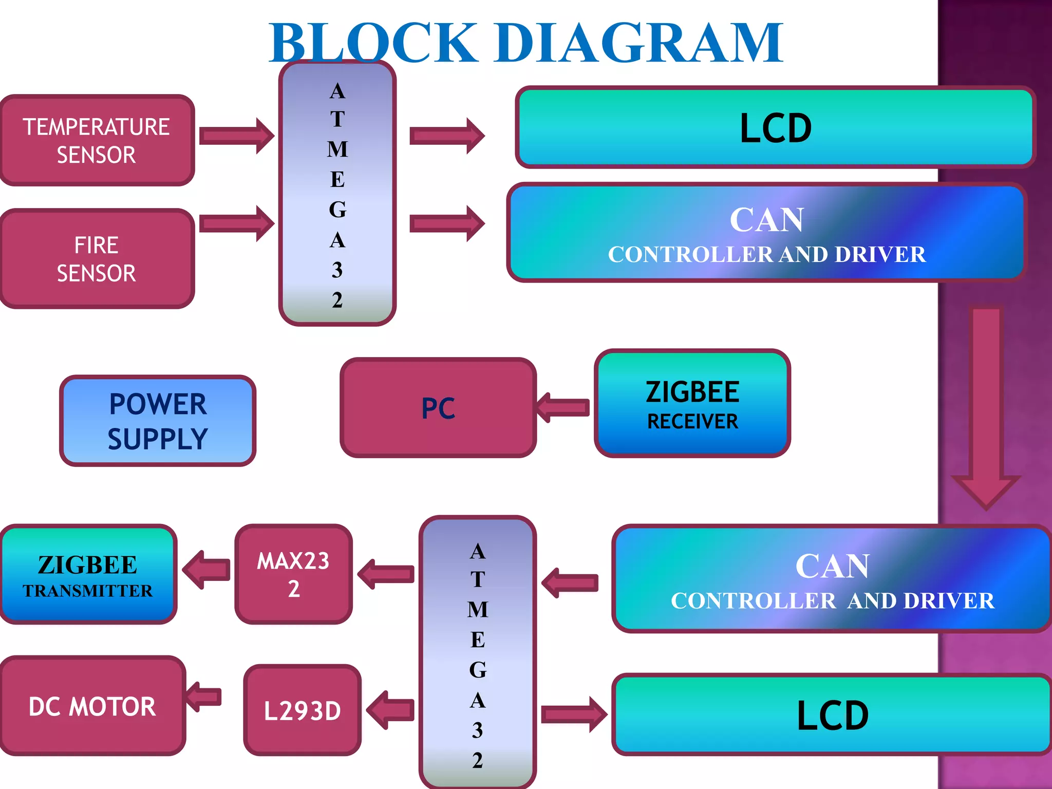
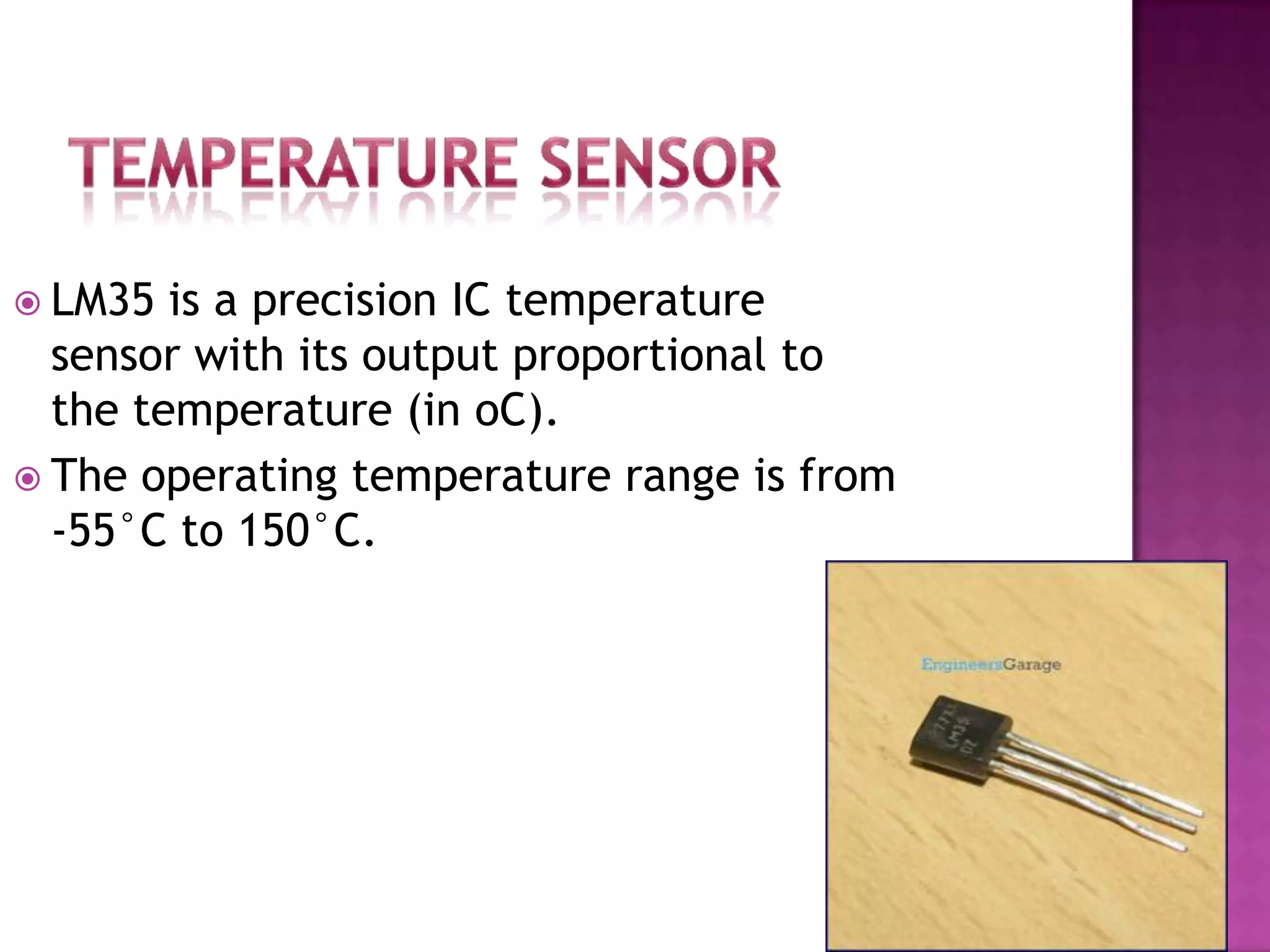
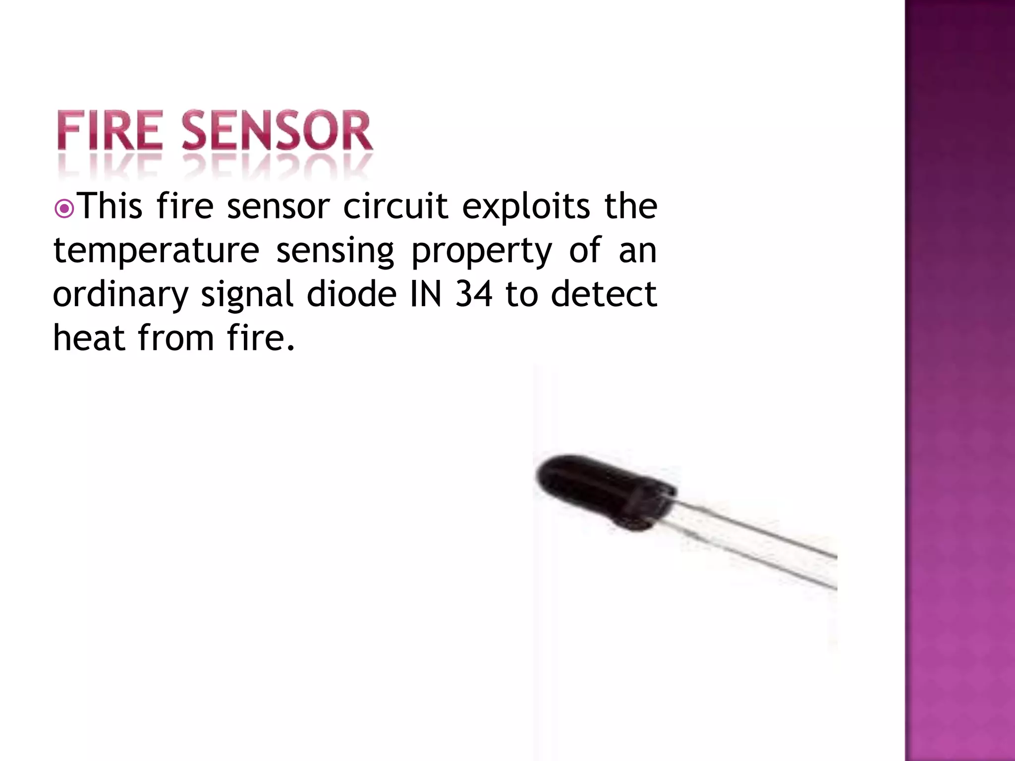
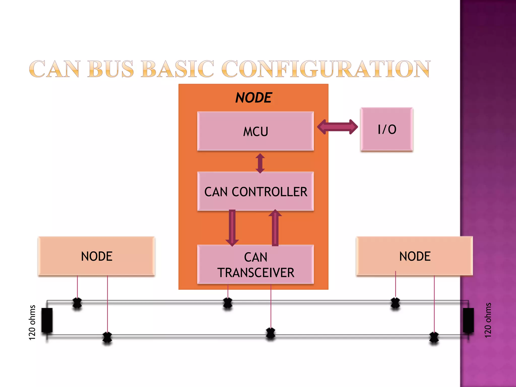
This document describes a system to transmit data from sensors to a receiver using both CAN and Zigbee communication protocols. It includes a temperature sensor, fire sensor, CAN controller and driver, Zigbee transmitter, and receiver connected to a PC. The system allows data from the sensors to be transmitted simultaneously over CAN and Zigbee to the receiver and PC. A block diagram shows the connections between components.
Zigbee is a technological standard designed for control and sensor networks based on IEEE 802.15.4. The standard is developed and promoted by the Zigbee Alliance.
ZigBee is the name of a specification for a suite of high level communication protocols using small, low-power digital radios based on the IEEE 802.15.4-2006 standard for wireless personal area networks (WPANs), such as wireless headphones connecting with cell phones via short-range radio. The technology is intended to be simpler and less expensive than other WPANs, such as Bluetooth. ZigBee is targeted at radio-frequency (RF) applications that require a low data rate, long battery life, and secure networking.
This presentation is based on the IETF draft draft-farrell-lpwan-lora-overview-01 and provides a brief overview of the LoRaWAN architecture. It was presented at the LPWAN WG meeting in IETF 98.
Wireless communication is rapidly growing, making it possible to design wireless network systems that can constantly collect, analyse, evaluate and validate our environment to get more control of the factors that influence it. With over a decade of intensive research and development, wireless sensor network technology has been emerging as viable solution to many innovative applications. In this project, we have developed a wireless TV audio transceiver (transmitter to multiple receivers) using microcontroller atmega 328 and nRF24L01 module. The nRF24L01 transceiver module uses the 2.4 GHz band and it can operate with band rates from 250 kbps up to 2 Mbps. If used in closed space and with lower band rate its range can reach up to 100 meters.
Intel IPSO/6LoWPAN solution for general wireless sensor network usman sarwar
The 6LoWPAN NBR is enabled on the Intel Baytrail platform with Linux. This solution can provide an open source gateway implementation of IPSO 6LoWPAN based solution. Kindly refer here to get details.
If you need more information or need to get more features please contact me thru LinkedIn or email
www.linkedin.com/hp/update/6178842682400567296
Usman Sarwar
IoT Connectivity Architect
usman.sarwar@intel.com
The objective of project is to improve end-users’ Healthcare experience through its IoT-based Healthcare services and to support business incubation scheme with better
regulatory support
IoT is a combination of hardware and software technology that produces trillions of data through connecting multiple devices and sensors with the cloud and making sense of data with intelligent tools
IoT in Healthcare is a heterogeneous computing, wirelessly communicating system of apps and devices that connects patients and health providers to diagnose, monitor, track and store vital statistics and medical information.
From The Guardian to Cisco, big business to small, it seems that everybody is talking about the Internet of Things — but what exactly is IoT and why does it matter?
Taking a deep dive, we explore the many faces of IoT in Healthcare. Technology research and advisory company, Gartner, currently place the Internet of Things at the peak of inflated expectations and there are certainly challenges. But IoT also holds real promise for healthcare and it is already making an impact today.
We demonstrate why the Internet of Things has a far reaching impact across all determinants of health and how it could lead to a broader model of healthcare. We look at some of the technologies that are available to buy or that are already in development today, whilst also exploring some of the very real challenges that integrating such technologies into healthcare presents. Finally, we offer some ideas about how you can get involved, whether you are a healthcare professional or not.
The objective of this project is to provide an enhancement in the current railway system. This project is basically divided into two modules depending on its working.
The 1st module will provide an automatic railway gate at a level crossing replacing the gates operated by the gatekeeper. It deals with two things: Firstly, it deals with the reduction of time for which the gate is being kept closed and secondly, to provide safety to the road users by reducing railway accidents and also gives a prior intimation to the driver if any vehicle is stuck on the track during the train arrival so that the driver can take necessary precautions.
The 2nd module will deal with a container which will be placed below the entire lavatories which will automatically detect the platform and get closed to maintain the cleanliness of the platform. Next as soon the train will pass the station the container will get open to propel the slurry contains somewhere outside the station.
International Journal of Engineering Research and Applications (IJERA) is an open access online peer reviewed international journal that publishes research and review articles in the fields of Computer Science, Neural Networks, Electrical Engineering, Software Engineering, Information Technology, Mechanical Engineering, Chemical Engineering, Plastic Engineering, Food Technology, Textile Engineering, Nano Technology & science, Power Electronics, Electronics & Communication Engineering, Computational mathematics, Image processing, Civil Engineering, Structural Engineering, Environmental Engineering, VLSI Testing & Low Power VLSI Design etc.
The Indian economy is classified into different sectors to simplify the analysis and understanding of economic activities. For Class 10, it's essential to grasp the sectors of the Indian economy, understand their characteristics, and recognize their importance. This guide will provide detailed notes on the Sectors of the Indian Economy Class 10, using specific long-tail keywords to enhance comprehension.
For more information, visit-www.vavaclasses.com
Students, digital devices and success - Andreas Schleicher - 27 May 2024..pptxEduSkills OECD
Andreas Schleicher presents at the OECD webinar ‘Digital devices in schools: detrimental distraction or secret to success?’ on 27 May 2024. The presentation was based on findings from PISA 2022 results and the webinar helped launch the PISA in Focus ‘Managing screen time: How to protect and equip students against distraction’ https://www.oecd-ilibrary.org/education/managing-screen-time_7c225af4-en and the OECD Education Policy Perspective ‘Students, digital devices and success’ can be found here - https://oe.cd/il/5yV
Unit 8 - Information and Communication Technology (Paper I).pdfThiyagu K
This slides describes the basic concepts of ICT, basics of Email, Emerging Technology and Digital Initiatives in Education. This presentations aligns with the UGC Paper I syllabus.
The Roman Empire A Historical Colossus.pdfkaushalkr1407
The Roman Empire, a vast and enduring power, stands as one of history's most remarkable civilizations, leaving an indelible imprint on the world. It emerged from the Roman Republic, transitioning into an imperial powerhouse under the leadership of Augustus Caesar in 27 BCE. This transformation marked the beginning of an era defined by unprecedented territorial expansion, architectural marvels, and profound cultural influence.
The empire's roots lie in the city of Rome, founded, according to legend, by Romulus in 753 BCE. Over centuries, Rome evolved from a small settlement to a formidable republic, characterized by a complex political system with elected officials and checks on power. However, internal strife, class conflicts, and military ambitions paved the way for the end of the Republic. Julius Caesar’s dictatorship and subsequent assassination in 44 BCE created a power vacuum, leading to a civil war. Octavian, later Augustus, emerged victorious, heralding the Roman Empire’s birth.
Under Augustus, the empire experienced the Pax Romana, a 200-year period of relative peace and stability. Augustus reformed the military, established efficient administrative systems, and initiated grand construction projects. The empire's borders expanded, encompassing territories from Britain to Egypt and from Spain to the Euphrates. Roman legions, renowned for their discipline and engineering prowess, secured and maintained these vast territories, building roads, fortifications, and cities that facilitated control and integration.
The Roman Empire’s society was hierarchical, with a rigid class system. At the top were the patricians, wealthy elites who held significant political power. Below them were the plebeians, free citizens with limited political influence, and the vast numbers of slaves who formed the backbone of the economy. The family unit was central, governed by the paterfamilias, the male head who held absolute authority.
Culturally, the Romans were eclectic, absorbing and adapting elements from the civilizations they encountered, particularly the Greeks. Roman art, literature, and philosophy reflected this synthesis, creating a rich cultural tapestry. Latin, the Roman language, became the lingua franca of the Western world, influencing numerous modern languages.
Roman architecture and engineering achievements were monumental. They perfected the arch, vault, and dome, constructing enduring structures like the Colosseum, Pantheon, and aqueducts. These engineering marvels not only showcased Roman ingenuity but also served practical purposes, from public entertainment to water supply.
This is a presentation by Dada Robert in a Your Skill Boost masterclass organised by the Excellence Foundation for South Sudan (EFSS) on Saturday, the 25th and Sunday, the 26th of May 2024.
He discussed the concept of quality improvement, emphasizing its applicability to various aspects of life, including personal, project, and program improvements. He defined quality as doing the right thing at the right time in the right way to achieve the best possible results and discussed the concept of the "gap" between what we know and what we do, and how this gap represents the areas we need to improve. He explained the scientific approach to quality improvement, which involves systematic performance analysis, testing and learning, and implementing change ideas. He also highlighted the importance of client focus and a team approach to quality improvement.
The Art Pastor's Guide to Sabbath | Steve ThomasonSteve Thomason
What is the purpose of the Sabbath Law in the Torah. It is interesting to compare how the context of the law shifts from Exodus to Deuteronomy. Who gets to rest, and why?
Synthetic Fiber Construction in lab .pptxPavel ( NSTU)
Synthetic fiber production is a fascinating and complex field that blends chemistry, engineering, and environmental science. By understanding these aspects, students can gain a comprehensive view of synthetic fiber production, its impact on society and the environment, and the potential for future innovations. Synthetic fibers play a crucial role in modern society, impacting various aspects of daily life, industry, and the environment. ynthetic fibers are integral to modern life, offering a range of benefits from cost-effectiveness and versatility to innovative applications and performance characteristics. While they pose environmental challenges, ongoing research and development aim to create more sustainable and eco-friendly alternatives. Understanding the importance of synthetic fibers helps in appreciating their role in the economy, industry, and daily life, while also emphasizing the need for sustainable practices and innovation.
Palestine last event orientationfvgnh .pptxRaedMohamed3
An EFL lesson about the current events in Palestine. It is intended to be for intermediate students who wish to increase their listening skills through a short lesson in power point.
How to Split Bills in the Odoo 17 POS ModuleCeline George
Bills have a main role in point of sale procedure. It will help to track sales, handling payments and giving receipts to customers. Bill splitting also has an important role in POS. For example, If some friends come together for dinner and if they want to divide the bill then it is possible by POS bill splitting. This slide will show how to split bills in odoo 17 POS.
Instructions for Submissions thorugh G- Classroom.pptxJheel Barad
This presentation provides a briefing on how to upload submissions and documents in Google Classroom. It was prepared as part of an orientation for new Sainik School in-service teacher trainees. As a training officer, my goal is to ensure that you are comfortable and proficient with this essential tool for managing assignments and fostering student engagement.
The French Revolution, which began in 1789, was a period of radical social and political upheaval in France. It marked the decline of absolute monarchies, the rise of secular and democratic republics, and the eventual rise of Napoleon Bonaparte. This revolutionary period is crucial in understanding the transition from feudalism to modernity in Europe.
For more information, visit-www.vavaclasses.com
2. To transmit the data from CAN transmitter to
CAN receiver and simultaneously from
Zigbee transmitter to receiver.
3. BLOCK DIAGRAM
A
TEMPERATURE T
M
LCD
SENSOR
E
G
CAN
FIRE A
CONTROLLER AND DRIVER
SENSOR 3
2
POWER ZIGBEE
PC RECEIVER
SUPPLY
MAX23 A
ZIGBEE
T CAN
TRANSMITTER 2 CONTROLLER AND DRIVER
M
E
G
DC MOTOR
LCD
A
L293D
3
2
4. LM35 is a precision IC temperature
sensor with its output proportional to
the temperature (in oC).
The operating temperature range is from
-55°C to 150°C.
5. This fire sensor circuit exploits the
temperature sensing property of an
ordinary signal diode IN 34 to detect
heat from fire.
6. Mini-Computer
Microprocessor
The Brains
Arithmetic Logic Unit (ALU)
Control Unit
Program/ Data Storage
Peripherals (Input/Output)
Low-Cost
7.
8. High-performance, Low-power AVR 8 bit
microcontroller
RISC architecture
The ATmega32 has 32 GPIO
32K Bytes of In-System Self-Programmable Flash
memory
2 KB RAM.
1024 Bytes EEPROM
Programmable Serial USART
9.
10. Bit 1 – Z: Zero Flag
Bit 0 – C: Carry Flag
Bit 7 – I: Global Interrupt Enable
Bit 5 – H: Half Carry Flag
Bit 6 – T: Bit Copy Storage
Bit 4 – S: Sign Bit, S = N ⊕V
Bit 2 – N: Negative Flag
Bit 3 – V: Two’s Complemenr
Overflow Flag
Bit 1 – Z: Zero Flag
Bit 0 – C: Carry Flag
16. APPLICATION
LAYER
PRESENTATION
LAYER
SESSION LAYER
TRANSPORT
LAYER
NETWORK
LAYER
DATA LINK LOGICAL LINK CONTROL
LAYER MEDIUM ACCESS CONTROL
PHYSI
PHYSICAL SIGNALING
CAL PHYSICAL MEDIUM ATTACHMENT
LAYER MEDIUM DEPENDENT INTERFACE
17. • The CAN protocol controller outputs a
serial data stream to the logic TXD input
of the MCP2551. The corresponding
TRANSMIT recessive or dominant state is output on
the CANH and CANL pins.
• The MCP2551 receives dominant or
recessive states on the same CANH and
CANL pins as the transmit occurs. These
states are output as logic levels on the
RECEIVE RXD pin for the CAN protocol controller to
receive CAN frames.
• A logic „1‟ on the TXD input turns off the
drivers to the CANH and CANL pins and the
RECESSIVE pins “float” to a nominal 2.5V via biasing
resistors.
STATE
• A logic „0‟ on the TXD input turns on the
CANH and CANL pin drivers.
DOMINANT
18. CONFIGURATION MODE
NORMAL MODE
SLEEP MODE
LISTEN –ONLY MODE
LOOP BACK MODE
19. CAN 2.0A (“standard CAN” 11-bit ID) Data Frame.
CAN 2.0B (“extended CAN” 29-bit ID) Data Frame.
19
20. CSMA/CD NDA – Carrier Sense Multiple Access/Collision avoidance by Non
Destructive arbitration
20
22. What is ZigBee?
Technological Standard Created for Control and
Sensor Networks
Based on the IEEE 802.15.4 Standard
Created by the ZigBee Alliance
Wireless personal area networks (WPANs)
High level communication
Frequency band up to 2.5 GHz
23. Data rates of 20 kbps and up to 250 kbps
Support for Low Latency Devices
CSMA-CA Channel Access
Handshaking
Low Power Usage consumption
3 Frequencies bands with 27 channels
Extremely low duty-cycle (<0.1%)
Supports large number of nodes
Easy to deploy
Very long battery life
Secure
Low cost
Can be used globally
24.
25. IEEE 802.15.4
Physical layer
•Activation and deactivation of the radio
transceiver
•Energy detection
•Link quality indicator
•Channel frequency selection
•Data transmission and reception
•CSMA-CA
MAC layer
•Generating network beacons
•Synchronizing
•PAN association and disassociation
•Device security
•GTS mechanism
•Reliability
26. IEEE Zigbee
802.15.4 device roles
device roles
FFD RFD
Coordinator Router End device
PAN
Coordinator device
coordinator
28. Functional Overview
• Superframe structure
• Data transfer model
• Frame structure
• Improving probability of successful delivery
• Power consumption considerations
• Security
32. Discard route
request
B
req. C
route
a
req.
route route reply T
S
req.
rou
te r route
eq. D
rou
te r
eq.
Unicast
Broadcast
Without routing capacity
34. CONCLUSION AND FUTURE SCOPE
In this application CAN uses multiple transmitter nodes to
acquire data from sensors and transmit the data in packets over a
CAN bus. Each transmitter consists of an AT Mega32 micro
controller. The CAN packets are received by a single receiver node
and stored to a secure digital card (SD Card) by using SPI protocol.
Editor's Notes
The main objective of this project is to transmit the data from can transmitter to can receiver and simultaneously to Zigbee transmitter to receiver. Whenever the temperature is increased /obstacle is detected the dc motor will automatically starts and vice-versa
The Status Register contains information about the result of the most recently executed arithmetic instruction. This information can be used for altering program flow in order to perform conditional operations.
CAN is an important embedded protocol-Primarily automotive, but used in many other places. With the use of CAN, point-to-point wiring is replaced by one serial bus connecting all control systems. This is accomplished by adding some CAN-specific hardware to each control unit that provides the "rules" or the protocol for transmitting and receiving information via the bus. Invented by Robert Bosch GmbH Asynchronous Serial Bus Absence of node addressing Message identifier specifies contents and priority Lowest message identifier has highest priority Non-destructive arbitration system by CSMA with collision detection Multi-master / Broadcasting concept Sophisticated error detection & handling system Industrial and Automotive Applications Number of nodes – not lmtd by the protocolNo node addressing,msgidspecifiers,contents n priorityEasy connection /disconnection of nodesBroadcast /multicast capability
The nodes are connected to the bus in a wired-and fashion: if just one node is driving the bus to a logical 0, then the whole bus is in that state regardless of the number of nodes transmitting a logical 1.Max. transfer rate of 1000 kilobits per second at a maximum bus length of 40 meters or 130 feet when using a twisted wire pair which is the most common bus medium used for CAN. Message length is short with a maximum of 8 data bytes per message and there is a low latency between transmission request and start of transmission. The messages are protected by a CRC type checksum
•These are the bus levels according to ISO-IS 11898. A recessive bit is represented by both CAN bus lines driven to a level of about 2.5 V so that the differential voltage between CAN_H and CAN_L is around 0 V.•A dominant bit is represented by CAN_H going to about 3.5 V and CAN_L going to about 1.5 V. This results in a differential voltage for a dominant bit of about 2V.
ISO11898 is the international standard for high-speed CAN communications Many network protocols are described using the seven layer Open System inter connection (OSI) model. The Controller Area Network (CAN) protocol defines the Data Link Layer and part of the Physical Layer in the OSI model. The remaining physical layer (and all of the higher layers) are not defined by the CAN specification. The physical layer uses differential transmission on a twisted pair wire. The bus uses Non-Return To Zero (NRZ) with bit-stuffing.These other layers can either be defined by the system designer, or they can be implemented using existing non-proprietary Higher Layer Protocols (HLPs) and physical layers.The Data Link Layer is defined by the CAN specification.The Logical Link Control (LLC) manages the overload control and notification, message filtering andrecovery management functions. The Medium Access Control (MAC) performs the data encapsulation/decapsulation,error detection and control, bit stuffing/destuffing and the serialization and deserialization functions.ISO-11898 specifies the physical layer to ensure compatibility between CAN transceivers.The Physical Medium Attachment (PMA) and MediumDependent Interface (MDI) are the two parts of the physical layer which are not defined by CAN. The Physical Signaling (PS) portion of the physical layer isdefined by the CAN specification. The system designer can choose any driver/receiver and transport medium as long as the PS requirements are met.
INTERFACES WITHN MC VIA SPI to simplify applications that require interfacing with can bus.MCP2515 HAS 5 MODES OF OPRATION:CONFIGURATION MODEThe MCP2515 must be initialized before activation. This is only possible if the device is in the Configuration mode. Configuration mode is automatically selected after power-up or a reset.NORMAL MODENormal mode is the standard operating mode of the MCP2515. In this mode, the device actively monitors all bus messages and generates acknowledge bits, error frames, etc. This is also the only mode in which the MCP2515 will transmit messages over the CAN bus.SLEEP MODEThe MCP2515 has an internal Sleep mode that is used to minimize the current consumption of the device. The SPI interface remains active for reading even when the MCP2515 is in Sleep mode, allowing access to all registers.LISTEN –ONLY MODEListen-only mode provides a means for the MCP2515 to receive all messages. Listen-only mode is a silent mode, meaning no messages will be transmitted while in this mode (including error flags or acknowledge signals).LOOP BACK MODELoopback mode will allow internal transmission of messages from the transmit buffers to the receive buffers without actually transmitting messages on the CAN bus. This mode can be used in system development and testing
Note 1: It is worth noting that the presence of an Acknowledgement Bit on the bus does not mean that any of the intended addressees has received the message. The only thing we know is that one or more nodes on the bus has received it correctlyNote 2: The Identifier in the Arbitration Field is not, despite of its name, necessarily identifying the contents of the message.SOF – Start of FrameIdentifier – Tells the content of message and priorityRTR – Remote Transmission Request IDE – Identifier extension (distinguishes between CAN standard,11 bit identifier, and CAN extended, 29 bit identifier.)DLC – Data Length CodeData – holds up to 8 bytes of dataCRC – “Cyclic Redundant Check” sumACK – AcknowledgeEOF – End of FrameIFS – Intermission Frame Space. Minimum number of bits separating consecutive messages.
Arbitration limits bus speed. Maximum speed = 2 x tpdtpd = propagation delay of electrical medium
Physical layer •a transmitter shall be capable of transmitting at least –3 dBm (0.5 mW), normally at 0 dBm (1 mW) •a receiver shall have a receiver maximum input level greater than or equal to –20 dBm (0.01 mW) Physical layer • 2450MHz is the most commonly used band for WSNs because: • it’s available worldwide without need for licensing • it has highest data rate achieved with simplest modulation • Sub1-GHz bands (915/868 MHz) provide better signal range than 2.4 GHz bandwhen starting the network the coordinator scans pre- configured channels and choose one with least activity detected • when joining the WPAN, a device scans through the given set of channels and report discovered networks to higher layers to permit joingenerating network beacons if the device is a coordinator • synchronizing to network beacons • supporting PAN association and disassociation• supporting device security • employing the CSMA-CA mechanism for channel access • handling and maintaining the GTS mechanism • providing a reliable link between two peer MAC entities
An ffd is capable of performing all duties described in IEEE standard and can accept any role in the network.anrfd has limited capabilities.foreg. An ffd can communicate with any otherdevice in a network,but an rfd can talk only with an ffd device.rfd devices are intended for very simple aplications such as turning on or off a switch.the processing power and memory size of rfd devices are normally less than those of ffd devicesDevice roles: in an ieee 802.15.4 n/w,anffd device can take three different roles:coordinator,pan coordinator and device.A coordinator is an ffd device that is capable of relaying messages.if the coordinator is also the principal controller of a personal area network(pan)it is called a pan coordinator.if a device is not acting as a coordinator,it is simply called a device.The zigbee standards uses slightly different terminology.azigbee coordinator is an ieee 802.15.4 pan coordinator……A zigbee end device has the least memory size and fewest processing capabilitiesandfeatures.an end device is least expensive device in the n/wThere are three different types of ZigBee devices:ZigBee coordinator (ZC): The most capable device, the coordinator forms the root of the network tree and might bridge to other networks. There is exactly one ZigBee coordinator in each network since it is the device that started the network originally. It is able to store information about the network, including acting as the Trust Centre & repository for security keys.ZigBee Router (ZR): As well as running an application function, a router can act as an intermediate router, passing on data from other devices.ZigBee End Device (ZED): Contains just enough functionality to talk to the parent node (either the coordinator or a router); it cannot relay data from other devices. This relationship allows the node to be asleep a significant amount of the time thereby giving long battery life. A ZED requires the least amount of memory, and therefore can be less expensive to manufacture than a ZR or ZC.
Star: n/w is simple in setup and deploymentData forwarding is possible only by coordinator(two hops only)Coverage area is limited by one hop transmission rangePeer to peer: data frames can be delivered via several intermediate nodeLarge spatial areas can be covered by a single n/wComplex packet routing algorithm are required
Superframe structure • thisstandard allows the optional use of a superframe structure. The format of the superframe is defined by the coordinator. The superframe is bounded by network beacons sent by the coordinator and is divided into 16 equally sized slotsTypes of data transfer transactionsDevice to coordinator,coordinator to device,device to device
In beacon-enabled networks, the special network nodes called ZigBee Routers transmit periodic beacons to confirm their presence to other network nodes. Nodes may sleep between beacons, thus lowering their duty cycle and extending their battery life.In non-beacon-enabled networks, an unslotted CSMA/CA channel access mechanism is used. In this type of network, ZigBee Routers typically have their receivers continuously active, requiring a more robust power supply.Because ZigBee can activate (go from sleep to active mode) in 15 msec or less, the latency can be very low and devices can be very responsive — particularly compared to Bluetooth wake-up delays, which are typically around three seconds. Because ZigBees can sleep most of the time, average power consumption can be very low, resulting in long battery life.
In this mode, the network coordinator will periodically "wake-up" and send out a beacon to the devices within its network. This beacon subsequently wakes up each device, who must determine if it has any message to receive. If not, the device returns to sleep, as will the network coordinator, once its job is complete. Non-beacon mode, on the other hand, is less coordinated, as any device can communicate with the coordinator at will. However, this operation can cause different devices within the network to interfere with one another, and the coordinator must always be awake to listen for signals, thus requiring more power.In any case, ZigBee obtains its overall low power consumption because the majority of network devices are able to remain inactive over long periods of time.
ZigBee standard defines the Data Link Controller (DLC) layer, Network layer (NWK) and ZigBee profiles. Profiles are an agreement on messages, message formats and processing actions.There are two types of ZigBee Profiles:Device Profile: This profile describes how general ZigBee device features are implemented, such as Binding, Device Discovery and Service Discovery.Application Profile: This profile is application specific and consists of a list of ZigBee Device Descriptions. Each of the descriptions work together to form an application.
The route discovery in a ZigBee network is similar to the AODV routing protocol Links with lower cost will be chosen into the routing path. The cost of a link is defined based on the packet delivery probability on that linkRoute discovery procedure The source broadcasts a route request packet Intermediate nodes will rebroadcast route request if They have routing discovery table capacitiesThe cost is lowerOtherwise, nodes will relay the request along the treeThe destination will choose the routing path with the lowest cost and then send a route reply