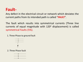
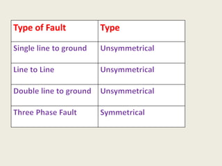
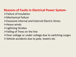
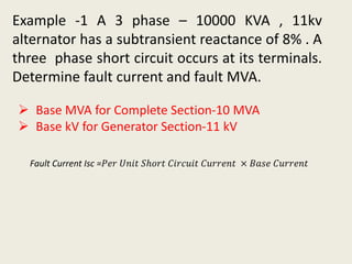
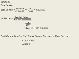
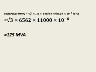
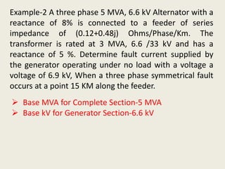
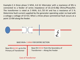
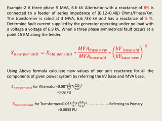
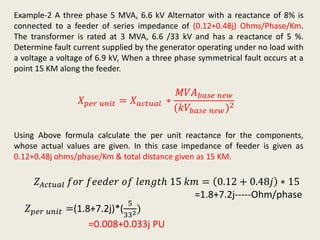
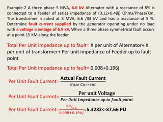
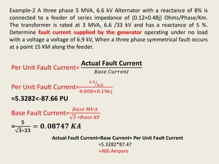
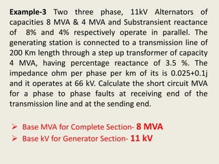
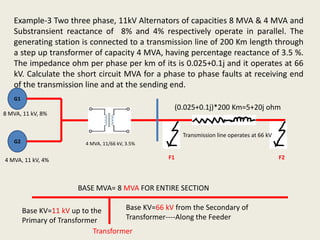
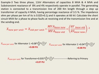
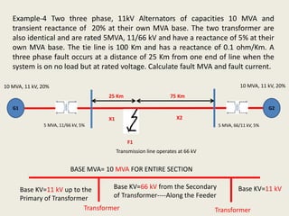
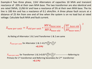
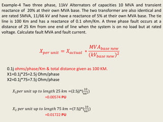
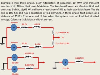
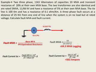
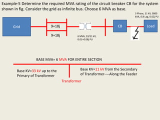
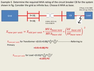
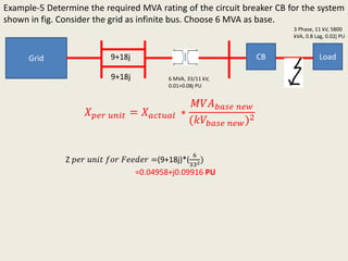
DEPARTMENT OF ELECTRICAL ENGINEERING
JSPMS
BHIVARABAISAWANTINSTITUTEOFTECHNOLOGYANDRESEARCH,
WAGHOLI,PUNE
A.Y. 2019-20 (SEM-II)
Class: T.E.
Subject: Power System-II
Prepared by Prof. S. D.
Gadekar
Santoshgadekar.919@gmail.com
Mob. No-9130827661
Fault-
Any defect in the electrical circuit or network which deviates the
current paths from its intended path is called “FAULT”.
The fault which results into symmetrical currents (Three line
currents of equal magnitude with 120ᵒ displacement) is called
symmetrical Faults (5%).
1. Three Phase to ground fault
2. Three Phase fault
Type of Fault Type
Reasons of Faults in Electrical Power System-
Failure of Insulation
Mechanical Failure
Excessive Internal and External Electric Stress
Heavy winds
Lightning Strokes
Falling of Trees on the line
Over voltage or under voltage due to switching surges
Vehicle accidents due to pole, towers etc
Three phase short circuit Analysis of Unloaded
Alternator-
The flux linkages in the armature circuits and the field
circuit can not changed suddenly by the application of short
circuit to the armature winding.
For maintaining these flux linkages constant large changes
of current may take place in both of the windings, when
short circuit occurs in order to keep their respective flux
linkages constant.
Direct-Axis Subtransient Reactance, 𝑋 𝑑
𝑖𝑖
𝑋 𝑑
𝑖𝑖
=𝑋𝑙 +
1
1
𝑋 𝑎
+
1
𝑋 𝑓
+
1
𝑋 𝑑𝑤
… … … . Ohm
Direct-Axis Transient Reactance, 𝑋 𝑑
𝑖
𝑋 𝑑
𝑖
=𝑋𝑙 +
1
1
𝑋 𝑎
+
1
𝑋 𝑓
… … … . Ohm
Direct-Axis Steady State Reactance, 𝑋 𝑑
𝑋 𝑑=𝑋𝑙 + 𝑋 𝑎 … … … . Ohm
𝑋 𝑑
𝑖𝑖
<𝑋 𝑑
𝑖
<𝑋 𝑑
Relation between direct axis
Reactance
3-Phase fault current transients in synchronous
generators
The current can be
represented as a transient
DC component added on top
of a symmetrical AC
component.
Before the fault, only AC
voltages and currents are
present, but immediately
after the fault, both AC and
DC currents are present.
Symmetrical AC component of the fault current:
There are three periods of time:
 Sub-transient period: first cycle or so after
the fault – AC current is very large and falls
rapidly;
 Transient period: current falls at a slower
rate;
 Steady-state period: current reaches its
steady value.
Some Important Formulae-
Isc Per Unit =
𝑃𝑒𝑟 𝑈𝑛𝑖𝑡 𝑣𝑜𝑙𝑡𝑎𝑔𝑒 𝑎𝑡 𝑓𝑎𝑢𝑙𝑡 𝑝𝑜𝑖𝑛𝑡
𝑃𝑒𝑟 𝑈𝑛𝑖𝑡 𝐸𝑞𝑢𝑖𝑣𝑎𝑙𝑒𝑛𝑡 𝑅𝑒𝑎𝑐𝑡𝑎𝑛𝑐𝑒
Per Unit Fault MVA = 3 × 𝑃𝑒𝑟 𝑈𝑛𝑖𝑡 𝐹𝑎𝑢𝑙𝑡 𝐶𝑢𝑟𝑟𝑒𝑛𝑡 × Per Unit Source Voltage
Fault MVA =
𝐵𝑎𝑠𝑒 𝑀𝑉𝐴
𝑃𝑈 𝐸𝑞𝑢𝑖𝑣𝑎𝑙𝑒𝑛𝑡 𝑅𝑒𝑎𝑐𝑡𝑎𝑛𝑐𝑒
(𝑀𝑉𝐴 𝐿𝑎𝑔𝑔𝑖𝑛𝑔)
Fault Current Isc =
𝐹𝑎𝑢𝑙𝑡 𝑀𝑉𝐴 × 103
3 ×𝐵𝑎𝑠𝑒 𝑘𝑉
𝐴
Fault MVA = 3 × Fault Current × Base Voltage × 10−6
Example -1 A 3 phase – 10000 KVA , 11kv
alternator has a subtransient reactance of 8% . A
three phase short circuit occurs at its terminals.
Determine fault current and fault MVA.
 Base MVA for Complete Section-10 MVA
 Base kV for Generator Section-11 kV
Fault Current Isc =𝑃𝑒𝑟 𝑈𝑛𝑖𝑡 𝑆ℎ𝑜𝑟𝑡 𝐶𝑖𝑟𝑐𝑢𝑖𝑡 𝐶𝑢𝑟𝑟𝑒𝑛𝑡 × 𝐵𝑎𝑠𝑒 𝐶𝑢𝑟𝑟𝑒𝑛𝑡
Solution :
Base Current,
Base Current =
Base MVA
3 Base kV
=
10
√3×11
= 0.525kA
Isc Per Unit =
𝑷𝒆𝒓 𝑼𝒏𝒊𝒕 𝑽𝒐𝒍𝒕𝒂𝒈𝒆
𝑷𝒆𝒓 𝑼𝒏𝒊𝒕 𝑹𝒆𝒂𝒄𝒕𝒂𝒏𝒄𝒆
=
𝟏
𝒋𝟎.𝟎𝟖
=12.5 < −900 Ampere
Fault Current Isc =𝑃𝑒𝑟 𝑈𝑛𝑖𝑡 𝑆ℎ𝑜𝑟𝑡 𝐶𝑖𝑟𝑐𝑢𝑖𝑡 𝐶𝑢𝑟𝑟𝑒𝑛𝑡 × 𝐵𝑎𝑠𝑒 𝐶𝑢𝑟𝑟𝑒𝑛𝑡
=12.5 × 525
=6562 A
Fault Power (MVA) = 𝟑 × 𝑰𝒔𝒄 × 𝑺𝒐𝒖𝒓𝒄𝒆 𝑽𝒐𝒍𝒕𝒂𝒈𝒆 × 𝟏𝟎−𝟔 𝑴𝑽𝑨
=√𝟑 × 𝟔𝟓𝟔𝟐 × 𝟏𝟏𝟎𝟎𝟎 × 𝟏𝟎−𝟔
=125 MVA
Example-2 A three phase 5 MVA, 6.6 kV Alternator with a
reactance of 8% is connected to a feeder of series
impedance of (0.12+0.48j) Ohms/Phase/Km. The
transformer is rated at 3 MVA, 6.6 /33 kV and has a
reactance of 5 %. Determine fault current supplied by
the generator operating under no load with a voltage a
voltage of 6.9 kV, When a three phase symmetrical fault
occurs at a point 15 KM along the feeder.
 Base MVA for Complete Section-5 MVA
 Base kV for Generator Section-6.6 kV
Example-2 A three phase 5 MVA, 6.6 kV Alternator with a reactance of 8% is
connected to a feeder of series impedance of (0.12+0.48j) Ohms/Phase/Km.
The transformer is rated at 3 MVA, 6.6 /33 kV and has a reactance of 5 %.
Determine fault current supplied by the generator operating under no load with
a voltage a voltage of 6.9 kV, When a three phase symmetrical fault occurs at a
point 15 KM along the feeder.
BASE MVA= 5 MVA FOR ENTIRE SECTION
Core of Transformer
Base KV=6.6 kV up to the
Primary of Transformer
Base KV=33 kV from the Secondary of
Transformer----Along the Feeder
Example-2 A three phase 5 MVA, 6.6 kV Alternator with a reactance of 8% is
connected to a feeder of series impedance of (0.12+0.48j) Ohms/Phase/Km.
The transformer is rated at 3 MVA, 6.6 /33 kV and has a reactance of 5 %.
Determine fault current supplied by the generator operating under no load with
a voltage a voltage of 6.9 kV, When a three phase symmetrical fault occurs at a
point 15 KM along the feeder.
𝑋 𝑛𝑒𝑤 𝑝𝑒𝑟 𝑢𝑛𝑖𝑡 = 𝑋 𝑜𝑙𝑑 𝑝𝑒𝑟 𝑢𝑛𝑖𝑡 ∗
𝑀𝑉𝐴 𝑏𝑎𝑠𝑒 𝑛𝑒𝑤
𝑀𝑉𝐴 𝑏𝑎𝑠𝑒 𝑜𝑙𝑑
∗
𝑘𝑉 𝑏𝑎𝑠𝑒 𝑜𝑙𝑑
𝑘𝑉𝑏𝑎𝑠𝑒 𝑛𝑒𝑤
2
Using Above formula calculate new values of per unit reactance for all the
components of given power system by referring the kV base and MVA base.
𝑋 𝑛𝑒𝑤 𝑝𝑒𝑟 𝑢𝑛𝑖𝑡 for Alternator=0.08*(
5
5
)*(
6.6
6.6
)2
=0.08 PU
𝑋 𝑛𝑒𝑤 𝑝𝑒𝑟 𝑢𝑛𝑖𝑡 for Transformer=0.05*(
5
3
)*(
6.6
6.6
)2------------------Referring to Primary
=0.0833 PU
Example-2 A three phase 5 MVA, 6.6 kV Alternator with a reactance of 8% is
connected to a feeder of series impedance of (0.12+0.48j) Ohms/Phase/Km.
The transformer is rated at 3 MVA, 6.6 /33 kV and has a reactance of 5 %.
Determine fault current supplied by the generator operating under no load with
a voltage a voltage of 6.9 kV, When a three phase symmetrical fault occurs at a
point 15 KM along the feeder.
𝑋 𝑝𝑒𝑟 𝑢𝑛𝑖𝑡 = 𝑋 𝑎𝑐𝑡𝑢𝑎𝑙 ∗
𝑀𝑉𝐴 𝑏𝑎𝑠𝑒 𝑛𝑒𝑤
(𝑘𝑉𝑏𝑎𝑠𝑒 𝑛𝑒𝑤)2
Using Above formula calculate the per unit reactance for the components,
whose actual values are given. In this case impedance of feeder is given as
0.12+0.48j ohms/phase/Km & total distance given as 15 KM.
𝑍 𝑝𝑒𝑟 𝑢𝑛𝑖𝑡 =(1.8+7.2j)*(
5
332)
=0.008+0.033j PU
𝑍 𝐴𝑐𝑡𝑢𝑎𝑙 𝑓𝑜𝑟 𝑓𝑒𝑒𝑑𝑒𝑟 𝑜𝑓 𝑙𝑒𝑛𝑔𝑡ℎ 15 𝑘𝑚 = 0.12 + 0.48𝑗 ∗ 15
=1.8+7.2j-----Ohm/phase
Example-2 A three phase 5 MVA, 6.6 kV Alternator with a reactance of 8% is
connected to a feeder of series impedance of (0.12+0.48j) Ohms/Phase/Km.
The transformer is rated at 3 MVA, 6.6 /33 kV and has a reactance of 5 %.
Determine fault current supplied by the generator operating under no load
with a voltage a voltage of 6.9 kV, When a three phase symmetrical fault occurs
at a point 15 KM along the feeder.
Total Per Unit impedance up to fault= X per unit of Alternator+ X
per unit of transformer+ Per unit impedance of Feeder up to fault
point
Total Per Unit impedance up to fault= 0.008+0.196j
Per Unit Fault Current=
Actual Fault Current
𝐵𝑎𝑠𝑒 𝐶𝑢𝑟𝑟𝑒𝑛𝑡
Per Unit Fault Current=
Per unit Voltage
𝑷𝒆𝒓 𝑼𝒏𝒊𝒕 𝑰𝒎𝒑𝒆𝒅𝒂𝒏𝒄𝒆 𝒖𝒑 𝒕𝒐 𝒇𝒂𝒖𝒍𝒕 𝒑𝒐𝒊𝒏𝒕
Per Unit Fault Current=
6.9
6.6
0.008+0.196𝑗
=5.3282<-87.66 PU
Example-2 A three phase 5 MVA, 6.6 kV Alternator with a reactance of 8% is
connected to a feeder of series impedance of (0.12+0.48j) Ohms/Phase/Km.
The transformer is rated at 3 MVA, 6.6 /33 kV and has a reactance of 5 %.
Determine fault current supplied by the generator operating under no load
with a voltage a voltage of 6.9 kV, When a three phase symmetrical fault occurs
at a point 15 KM along the feeder.
Per Unit Fault Current=
Actual Fault Current
𝐵𝑎𝑠𝑒 𝐶𝑢𝑟𝑟𝑒𝑛𝑡
Per Unit Fault Current=
6.9
6.6
0.008+0.196𝑗
=5.3282<-87.66 PU
Base Fault Current=
𝐵𝑎𝑠𝑒 𝑀𝑉𝐴
3 ∗𝐵𝑎𝑠𝑒 𝑘𝑉
=
𝟓
𝟑∗𝟑𝟑
= 𝟎. 𝟎𝟖𝟕𝟒𝟕 𝑲𝑨
Actual Fault Current=Base Current∗ Per Unit Fault Current
=5.3282*87.47
=466 Ampere
Example-3 Two three phase, 11kV Alternators of
capacities 8 MVA & 4 MVA and Substransient reactance
of 8% and 4% respectively operate in parallel. The
generating station is connected to a transmission line of
200 Km length through a step up transformer of capacity
4 MVA, having percentage reactance of 3.5 %. The
impedance ohm per phase per km of its is 0.025+0.1j
and it operates at 66 kV. Calculate the short circuit MVA
for a phase to phase faults at receiving end of the
transmission line and at the sending end.
 Base MVA for Complete Section- 8 MVA
 Base kV for Generator Section- 11 kV
Example-3 Two three phase, 11kV Alternators of capacities 8 MVA & 4 MVA and
Substransient reactance of 8% and 4% respectively operate in parallel. The
generating station is connected to a transmission line of 200 Km length through
a step up transformer of capacity 4 MVA, having percentage reactance of 3.5 %.
The impedance ohm per phase per km of its is 0.025+0.1j and it operates at 66
kV. Calculate the short circuit MVA for a phase to phase faults at receiving end
of the transmission line and at the sending end.
G1
BASE MVA= 8 MVA FOR ENTIRE SECTION
Transformer
Base KV=11 kV up to the
Primary of Transformer
Base KV=66 kV from the Secondary of
Transformer----Along the Feeder
(0.025+0.1j)*200 Km=5+20j ohm
G2
8 MVA, 11 kV, 8%
4 MVA, 11 kV, 4%
4 MVA, 11/66 kV, 3.5%
Transmission line operates at 66 kV
F1 F2
Example-3 Two three phase, 11kV Alternators of capacities 8 MVA & 4 MVA and
Substransient reactance of 8% and 4% respectively operate in parallel. The generating
station is connected to a transmission line of 200 Km length through a step up
transformer of capacity 4 MVA, having percentage reactance of 3.5 %. The impedance
ohm per phase per km of its is 0.025+0.1j and it operates at 66 kV. Calculate the short
circuit MVA for a phase to phase faults at receiving end of the transmission line and at
the sending end.
𝑋 𝑛𝑒𝑤 𝑝𝑒𝑟 𝑢𝑛𝑖𝑡 = 𝑋 𝑜𝑙𝑑 𝑝𝑒𝑟 𝑢𝑛𝑖𝑡 ∗
𝑀𝑉𝐴 𝑏𝑎𝑠𝑒 𝑛𝑒𝑤
𝑀𝑉𝐴 𝑏𝑎𝑠𝑒 𝑜𝑙𝑑
∗
𝑘𝑉 𝑏𝑎𝑠𝑒 𝑜𝑙𝑑
𝑘𝑉𝑏𝑎𝑠𝑒 𝑛𝑒𝑤
2
𝑋 𝑛𝑒𝑤 𝑝𝑒𝑟 𝑢𝑛𝑖𝑡 for Alternator 1 =0.08*(
8
8
)*(
11
11
)2
=0.08 PU
𝑋 𝑛𝑒𝑤 𝑝𝑒𝑟 𝑢𝑛𝑖𝑡 for Transformer=0.035*(
8
4
)*(
11
11
)2------------------Referring to Primary
=0.07 PU
𝑋 𝑛𝑒𝑤 𝑝𝑒𝑟 𝑢𝑛𝑖𝑡 for Alternator 2 =0.04*(
8
4
)*(
11
11
)2
=0.08 PU
Example-3 Two three phase, 11kV Alternators of capacities 8 MVA & 4 MVA and
Substransient reactance of 8% and 4% respectively operate in parallel. The generating
station is connected to a transmission line of 200 Km length through a step up
transformer of capacity 4 MVA, having percentage reactance of 3.5 %. The impedance
ohm per phase per km of its is 0.025+0.1j and it operates at 66 kV. Calculate the short
circuit MVA for a phase to phase faults at receiving end of the transmission line and at
the sending end.
𝑋 𝑝𝑒𝑟 𝑢𝑛𝑖𝑡 = 𝑋 𝑎𝑐𝑡𝑢𝑎𝑙 ∗
𝑀𝑉𝐴 𝑏𝑎𝑠𝑒 𝑛𝑒𝑤
(𝑘𝑉𝑏𝑎𝑠𝑒 𝑛𝑒𝑤)2
Using Above formula calculate the per unit reactance for the components,
whose actual values are given. In this case impedance of feeder is given as
0.025+0.1j ohms/phase/Km & total distance given as 200 KM.
𝑍 𝑝𝑒𝑟 𝑢𝑛𝑖𝑡 =(5+20j)*(
8
662)
=0.0092+0.0368j PU
𝑍 𝐴𝑐𝑡𝑢𝑎𝑙 𝑓𝑜𝑟 𝑓𝑒𝑒𝑑𝑒𝑟 𝑜𝑓 𝑙𝑒𝑛𝑔𝑡ℎ 200 𝑘𝑚 = 0.025 + 0.1𝑗 ∗200
=5+20j-----Ohm/phase
Example-3 Two three phase, 11kV Alternators of capacities 8 MVA & 4 MVA and
Substransient reactance of 8% and 4% respectively operate in parallel. The generating
station is connected to a transmission line of 200 Km length through a step up
transformer of capacity 4 MVA, having percentage reactance of 3.5 %. The impedance
ohm per phase per km of its is 0.025+0.1j and it operates at 66 kV. Calculate the short
circuit MVA for a phase to phase faults at receiving end of the transmission line and at
the sending end.
G1
G2
0.08 PU
Transmission line operates at 66 kV0.08 PU
0.07 PU 0.0092+0.0368j PU
E1=1 PU
E2=1 PU
G
Transmission line operates at 66 kV
0.04 PU 0.07 PU 0.0092+0.0368j PU
E=1 PU
F1 F2
F1 F2
Example-3 Two three phase, 11kV Alternators of capacities 8 MVA & 4 MVA and
Substransient reactance of 8% and 4% respectively operate in parallel. The generating
station is connected to a transmission line of 200 Km length through a step up
transformer of capacity 4 MVA, having percentage reactance of 3.5 %. The impedance
ohm per phase per km of its is 0.025+0.1j and it operates at 66 kV. Calculate the short
circuit MVA for a phase to phase faults at receiving end of the transmission line and
at the sending end.
Fault MVA =
𝑩𝒂𝒔𝒆 𝑴𝑽𝑨
𝑷𝑼 𝑬𝒒𝒖𝒊𝒗𝒂𝒍𝒆𝒏𝒕 𝑹𝒆𝒂𝒄𝒕𝒂𝒏𝒄𝒆
G
Transmission line operates at 66 kV
0.04 PU 0.07 PU 0.0092+0.0368j PU
E=1 PU
F1 F2
Fault MVA at F1=
8
0.04+0.07 𝑗
=72.72 MVA Lagging
Fault MVA at F2=
8
0.04+0.07 𝑗+(0.0092+0.0368𝑗)
=54.38 MVA Lagging
Example-4 Two three phase, 11kV Alternators of
capacities 10 MVA and transient reactance of 20% at
their own MVA base. The two transformer are also
identical and are rated 5MVA, 11/66 kV and have a
reactance of 5% at their own MVA base. The tie line is
100 Km and has a reactance of 0.1 ohm/Km. A three
phase fault occurs at a distance of 25 Km from one end
of line when the system is on no load but at rated
voltage. Calculate fault MVA and fault current.
 Base MVA for Complete Section- 10 MVA
 Base kV for Generator Section- 11 kV
Example-4 Two three phase, 11kV Alternators of capacities 10 MVA and
transient reactance of 20% at their own MVA base. The two transformer are
also identical and are rated 5MVA, 11/66 kV and have a reactance of 5% at their
own MVA base. The tie line is 100 Km and has a reactance of 0.1 ohm/Km. A
three phase fault occurs at a distance of 25 Km from one end of line when the
system is on no load but at rated voltage. Calculate fault MVA and fault current.
G1
BASE MVA= 10 MVA FOR ENTIRE SECTION
Transformer
Base KV=11 kV up to the
Primary of Transformer
Base KV=66 kV from the Secondary
of Transformer----Along the Feeder
G2
10 MVA, 11 kV, 20% 10 MVA, 11 kV, 20%
5 MVA, 11/66 kV, 5%
Transmission line operates at 66 kV
F1
5 MVA, 66/11 kV, 5%
25 Km 75 Km
Transformer
Base KV=11 kV
X1 X2
Example-4 Two three phase, 11kV Alternators of capacities 10 MVA and transient
reactance of 20% at their own MVA base. The two transformer are also identical and
are rated 5MVA, 11/66 kV and have a reactance of 5% at their own MVA base. The tie
line is 100 Km and has a reactance of 0.1 ohm/Km. A three phase fault occurs at a
distance of 25 Km from one end of line when the system is on no load but at rated
voltage. Calculate fault MVA and fault current.
𝑋 𝑛𝑒𝑤 𝑝𝑒𝑟 𝑢𝑛𝑖𝑡 = 𝑋 𝑜𝑙𝑑 𝑝𝑒𝑟 𝑢𝑛𝑖𝑡 ∗
𝑀𝑉𝐴 𝑏𝑎𝑠𝑒 𝑛𝑒𝑤
𝑀𝑉𝐴 𝑏𝑎𝑠𝑒 𝑜𝑙𝑑
∗
𝑘𝑉 𝑏𝑎𝑠𝑒 𝑜𝑙𝑑
𝑘𝑉𝑏𝑎𝑠𝑒 𝑛𝑒𝑤
2
𝑋 𝑛𝑒𝑤 𝑝𝑒𝑟 𝑢𝑛𝑖𝑡 for Alternator 1 & 2 =0.2*(
10
10
)*(
11
11
)2
=0.2 PU
𝑋 𝑛𝑒𝑤 𝑝𝑒𝑟 𝑢𝑛𝑖𝑡 for Transformer 1 & 2=0.05*(
10
5
)*(
11
11
)2------------------Referring to
Primary for 1st transformer and Referring Secondary for 2nd transformer
=0.1 PU
As Rating of Alternator 1 & 2 and Transformer 1 & 2 are same
Example-4 Two three phase, 11kV Alternators of capacities 10 MVA and transient
reactance of 20% at their own MVA base. The two transformer are also identical and
are rated 5MVA, 11/66 kV and have a reactance of 5% at their own MVA base. The tie
line is 100 Km and has a reactance of 0.1 ohm/Km. A three phase fault occurs at a
distance of 25 Km from one end of line when the system is on no load but at rated
voltage. Calculate fault MVA and fault current.
𝑋 𝑝𝑒𝑟 𝑢𝑛𝑖𝑡 = 𝑋 𝑎𝑐𝑡𝑢𝑎𝑙 ∗
𝑀𝑉𝐴 𝑏𝑎𝑠𝑒 𝑛𝑒𝑤
(𝑘𝑉𝑏𝑎𝑠𝑒 𝑛𝑒𝑤)2
0.1j ohms/phase/Km & total distance given as 100 KM.
X1=0.1j*25=2.5j Ohm/phase
X2=0.1j*75=7.5j Ohm/phase
𝑋1 𝑝𝑒𝑟 𝑢𝑛𝑖𝑡 𝑢𝑝 𝑡𝑜 𝑙𝑒𝑛𝑔𝑡ℎ 25 𝑘𝑚 =(2.5j)*(
10
662)
=0.00574 PU
𝑋2 𝑝𝑒𝑟 𝑢𝑛𝑖𝑡 𝑢𝑝 𝑡𝑜 𝑙𝑒𝑛𝑔𝑡ℎ 75 𝑘𝑚 =(7.5j)*(
10
662)
=0.01722 PU
Example-4 Two three phase, 11kV Alternators of capacities 10 MVA and transient
reactance of 20% at their own MVA base. The two transformer are also identical and
are rated 5MVA, 11/66 kV and have a reactance of 5% at their own MVA base. The tie
line is 100 Km and has a reactance of 0.1 ohm/Km. A three phase fault occurs at a
distance of 25 Km from one end of line when the system is on no load but at rated
voltage. Calculate fault MVA and fault current.
0.2 PU
0.2 PU
0.1 PU
E1=1 PU
E2=1 PU
0.1 PU
𝑿 𝟏 =0.00574 PU
𝑿 𝟐 = 0.01722 PU
G1
G2
0.30574 PU
E1=1 PU
E2=1 PU
0.31722 PU
G
E1=1 PU
0.1557 PU
G2
G1
F1
Example-4 Two three phase, 11kV Alternators of capacities 10 MVA and transient
reactance of 20% at their own MVA base. The two transformer are also identical and
are rated 5MVA, 11/66 kV and have a reactance of 5% at their own MVA base. The tie
line is 100 Km and has a reactance of 0.1 ohm/Km. A three phase fault occurs at a
distance of 25 Km from one end of line when the system is on no load but at rated
voltage. Calculate fault MVA and fault current.
Fault MVA =
𝑩𝒂𝒔𝒆 𝑴𝑽𝑨
𝑷𝑼 𝑬𝒒𝒖𝒊𝒗𝒂𝒍𝒆𝒏𝒕 𝑹𝒆𝒂𝒄𝒕𝒂𝒏𝒄𝒆
Fault MVA =
10
0.1557𝑗
=64.3 MVA Lagging
G1
E1=1 PU
0.1557 PU
Fault Current Isc =
𝐹𝑎𝑢𝑙𝑡 𝑀𝑉𝐴 × 103
3 ×𝐵𝑎𝑠𝑒 𝑘𝑉
𝐴 Fault Current Isc =
64.3 × 10³
3 ×66
𝐴
=562 Ampere
Example-5 Determine the required MVA rating of the circuit breaker CB for the system
shown in fig. Consider the grid as infinite bus. Choose 6 MVA as base.
Grid CB Load
6 MVA, 33/11 kV,
0.01+0.08j PU
3 Phase, 11 kV, 5800
kVA, 0.8 Lag, 0.02j PU
9+18j
9+18j
BASE MVA= 6 MVA FOR ENTIRE SECTION
Transformer
Base KV=33 kV up to the
Primary of Transformer
Base KV=11 kV from the Secondary
of Transformer----Along the Feeder
Example-5 Determine the required MVA rating of the circuit breaker CB for the system
shown in fig. Consider the grid as infinite bus. Choose 6 MVA as base.
Grid CB Load
6 MVA, 33/11 kV,
0.01+0.08j PU
3 Phase, 11 kV, 5800
kVA, 0.8 Lag, 0.02j PU
9+18j
9+18j
𝑋 𝑛𝑒𝑤 𝑝𝑒𝑟 𝑢𝑛𝑖𝑡 = 𝑋 𝑜𝑙𝑑 𝑝𝑒𝑟 𝑢𝑛𝑖𝑡 ∗
𝑀𝑉𝐴 𝑏𝑎𝑠𝑒 𝑛𝑒𝑤
𝑀𝑉𝐴 𝑏𝑎𝑠𝑒 𝑜𝑙𝑑
∗
𝑘𝑉 𝑏𝑎𝑠𝑒 𝑜𝑙𝑑
𝑘𝑉𝑏𝑎𝑠𝑒 𝑛𝑒𝑤
2
𝑋 𝑛𝑒𝑤 𝑝𝑒𝑟 𝑢𝑛𝑖𝑡 for Transformer =(0.01+0.08j)*(
6
6
)*(
33
33
)2
------------------Referring to
Primary
=0.01+0.08j PU
𝑋 𝑛𝑒𝑤 𝑝𝑒𝑟 𝑢𝑛𝑖𝑡 for Load =(0.02j)*(
6
5.8
)*(
11
11
)2
=0.207j PU
Example-5 Determine the required MVA rating of the circuit breaker CB for the system
shown in fig. Consider the grid as infinite bus. Choose 6 MVA as base.
Grid CB Load
6 MVA, 33/11 kV,
0.01+0.08j PU
3 Phase, 11 kV, 5800
kVA, 0.8 Lag, 0.02j PU
9+18j
9+18j
𝑋 𝑝𝑒𝑟 𝑢𝑛𝑖𝑡 = 𝑋 𝑎𝑐𝑡𝑢𝑎𝑙 ∗
𝑀𝑉𝐴 𝑏𝑎𝑠𝑒 𝑛𝑒𝑤
(𝑘𝑉𝑏𝑎𝑠𝑒 𝑛𝑒𝑤)2
Z 𝑝𝑒𝑟 𝑢𝑛𝑖𝑡 𝑓𝑜𝑟 𝐹𝑒𝑒𝑑𝑒𝑟 =(9+18j)*(
6
332)
=0.04958+j0.09916 PU
Example-5 Determine the required MVA rating of the circuit breaker CB for the system
shown in fig. Consider the grid as infinite bus. Choose 6 MVA as base.
Grid CB Load
6 MVA, 33/11 kV,
0.01+0.08j PU
3 Phase, 11 kV, 5800
kVA, 0.8 Lag, 0.02j PU
9+18j
9+18j
G CB
0.04958+j0.09916 PU
0.04958+j0.09916 PU
0.01+0.08j PU 0.207j PU
Equivalent impedance from grid to fault point, 𝑍 𝑒𝑞 = 0.13417 < 74.97° Ohm
Fault MVA =
𝑩𝒂𝒔𝒆 𝑴𝑽𝑨
𝑷𝑼 𝑬𝒒𝒖𝒊𝒗𝒂𝒍𝒆𝒏𝒕 𝑹𝒆𝒂𝒄𝒕𝒂𝒏𝒄𝒆
=
𝟔
𝟎.𝟏𝟑𝟒𝟏𝟕
= 𝟒𝟒. 𝟕𝟐 𝑴𝑽𝑨
Current Limiting Reactors-
A current limiting reactor, also sometimes called a series reactor, is an
inductive coil having a large inductive reactance in comparison to its
reactance and is used for limiting short circuit currents during fault
conditions.
Functions-
 Protective reactors are used to reduce flow of current in to a short
circuit.
 It is used to reduce the magnitude of voltage disturbances caused by
short circuit.
 They also localize the fault by limiting the current that flows into the
fault from other healthy feeders or part of the system.
 They reduce the duty imposed on switching equipment during short
circuits to be within economical ratings.
Types of Current Limiting Reactors-
1. Generator Reactor-
in series with the generators
2. Feeder Reactor-
in series with the feeder
2. Busbar Reactor-
a. Ring type
b. Tie bar type
G1
G2
Feeder
Busbar
Feeder
Busbar
G2
G1
Any Questions
?????????
Thank You

Symmetrical Fault Analysis

  • 1.
    DEPARTMENT OF ELECTRICALENGINEERING JSPMS BHIVARABAISAWANTINSTITUTEOFTECHNOLOGYANDRESEARCH, WAGHOLI,PUNE A.Y. 2019-20 (SEM-II) Class: T.E. Subject: Power System-II Prepared by Prof. S. D. Gadekar Santoshgadekar.919@gmail.com Mob. No-9130827661
  • 2.
    Fault- Any defect inthe electrical circuit or network which deviates the current paths from its intended path is called “FAULT”. The fault which results into symmetrical currents (Three line currents of equal magnitude with 120ᵒ displacement) is called symmetrical Faults (5%). 1. Three Phase to ground fault 2. Three Phase fault
  • 3.
  • 4.
    Reasons of Faultsin Electrical Power System- Failure of Insulation Mechanical Failure Excessive Internal and External Electric Stress Heavy winds Lightning Strokes Falling of Trees on the line Over voltage or under voltage due to switching surges Vehicle accidents due to pole, towers etc
  • 5.
    Three phase shortcircuit Analysis of Unloaded Alternator- The flux linkages in the armature circuits and the field circuit can not changed suddenly by the application of short circuit to the armature winding. For maintaining these flux linkages constant large changes of current may take place in both of the windings, when short circuit occurs in order to keep their respective flux linkages constant.
  • 6.
    Direct-Axis Subtransient Reactance,𝑋 𝑑 𝑖𝑖 𝑋 𝑑 𝑖𝑖 =𝑋𝑙 + 1 1 𝑋 𝑎 + 1 𝑋 𝑓 + 1 𝑋 𝑑𝑤 … … … . Ohm
  • 7.
    Direct-Axis Transient Reactance,𝑋 𝑑 𝑖 𝑋 𝑑 𝑖 =𝑋𝑙 + 1 1 𝑋 𝑎 + 1 𝑋 𝑓 … … … . Ohm
  • 8.
    Direct-Axis Steady StateReactance, 𝑋 𝑑 𝑋 𝑑=𝑋𝑙 + 𝑋 𝑎 … … … . Ohm
  • 9.
    𝑋 𝑑 𝑖𝑖 <𝑋 𝑑 𝑖 <𝑋𝑑 Relation between direct axis Reactance
  • 10.
    3-Phase fault currenttransients in synchronous generators The current can be represented as a transient DC component added on top of a symmetrical AC component. Before the fault, only AC voltages and currents are present, but immediately after the fault, both AC and DC currents are present.
  • 11.
    Symmetrical AC componentof the fault current: There are three periods of time:  Sub-transient period: first cycle or so after the fault – AC current is very large and falls rapidly;  Transient period: current falls at a slower rate;  Steady-state period: current reaches its steady value.
  • 12.
    Some Important Formulae- IscPer Unit = 𝑃𝑒𝑟 𝑈𝑛𝑖𝑡 𝑣𝑜𝑙𝑡𝑎𝑔𝑒 𝑎𝑡 𝑓𝑎𝑢𝑙𝑡 𝑝𝑜𝑖𝑛𝑡 𝑃𝑒𝑟 𝑈𝑛𝑖𝑡 𝐸𝑞𝑢𝑖𝑣𝑎𝑙𝑒𝑛𝑡 𝑅𝑒𝑎𝑐𝑡𝑎𝑛𝑐𝑒 Per Unit Fault MVA = 3 × 𝑃𝑒𝑟 𝑈𝑛𝑖𝑡 𝐹𝑎𝑢𝑙𝑡 𝐶𝑢𝑟𝑟𝑒𝑛𝑡 × Per Unit Source Voltage Fault MVA = 𝐵𝑎𝑠𝑒 𝑀𝑉𝐴 𝑃𝑈 𝐸𝑞𝑢𝑖𝑣𝑎𝑙𝑒𝑛𝑡 𝑅𝑒𝑎𝑐𝑡𝑎𝑛𝑐𝑒 (𝑀𝑉𝐴 𝐿𝑎𝑔𝑔𝑖𝑛𝑔) Fault Current Isc = 𝐹𝑎𝑢𝑙𝑡 𝑀𝑉𝐴 × 103 3 ×𝐵𝑎𝑠𝑒 𝑘𝑉 𝐴 Fault MVA = 3 × Fault Current × Base Voltage × 10−6
  • 13.
    Example -1 A3 phase – 10000 KVA , 11kv alternator has a subtransient reactance of 8% . A three phase short circuit occurs at its terminals. Determine fault current and fault MVA.  Base MVA for Complete Section-10 MVA  Base kV for Generator Section-11 kV Fault Current Isc =𝑃𝑒𝑟 𝑈𝑛𝑖𝑡 𝑆ℎ𝑜𝑟𝑡 𝐶𝑖𝑟𝑐𝑢𝑖𝑡 𝐶𝑢𝑟𝑟𝑒𝑛𝑡 × 𝐵𝑎𝑠𝑒 𝐶𝑢𝑟𝑟𝑒𝑛𝑡
  • 14.
    Solution : Base Current, BaseCurrent = Base MVA 3 Base kV = 10 √3×11 = 0.525kA Isc Per Unit = 𝑷𝒆𝒓 𝑼𝒏𝒊𝒕 𝑽𝒐𝒍𝒕𝒂𝒈𝒆 𝑷𝒆𝒓 𝑼𝒏𝒊𝒕 𝑹𝒆𝒂𝒄𝒕𝒂𝒏𝒄𝒆 = 𝟏 𝒋𝟎.𝟎𝟖 =12.5 < −900 Ampere Fault Current Isc =𝑃𝑒𝑟 𝑈𝑛𝑖𝑡 𝑆ℎ𝑜𝑟𝑡 𝐶𝑖𝑟𝑐𝑢𝑖𝑡 𝐶𝑢𝑟𝑟𝑒𝑛𝑡 × 𝐵𝑎𝑠𝑒 𝐶𝑢𝑟𝑟𝑒𝑛𝑡 =12.5 × 525 =6562 A
  • 15.
    Fault Power (MVA)= 𝟑 × 𝑰𝒔𝒄 × 𝑺𝒐𝒖𝒓𝒄𝒆 𝑽𝒐𝒍𝒕𝒂𝒈𝒆 × 𝟏𝟎−𝟔 𝑴𝑽𝑨 =√𝟑 × 𝟔𝟓𝟔𝟐 × 𝟏𝟏𝟎𝟎𝟎 × 𝟏𝟎−𝟔 =125 MVA
  • 16.
    Example-2 A threephase 5 MVA, 6.6 kV Alternator with a reactance of 8% is connected to a feeder of series impedance of (0.12+0.48j) Ohms/Phase/Km. The transformer is rated at 3 MVA, 6.6 /33 kV and has a reactance of 5 %. Determine fault current supplied by the generator operating under no load with a voltage a voltage of 6.9 kV, When a three phase symmetrical fault occurs at a point 15 KM along the feeder.  Base MVA for Complete Section-5 MVA  Base kV for Generator Section-6.6 kV
  • 17.
    Example-2 A threephase 5 MVA, 6.6 kV Alternator with a reactance of 8% is connected to a feeder of series impedance of (0.12+0.48j) Ohms/Phase/Km. The transformer is rated at 3 MVA, 6.6 /33 kV and has a reactance of 5 %. Determine fault current supplied by the generator operating under no load with a voltage a voltage of 6.9 kV, When a three phase symmetrical fault occurs at a point 15 KM along the feeder. BASE MVA= 5 MVA FOR ENTIRE SECTION Core of Transformer Base KV=6.6 kV up to the Primary of Transformer Base KV=33 kV from the Secondary of Transformer----Along the Feeder
  • 18.
    Example-2 A threephase 5 MVA, 6.6 kV Alternator with a reactance of 8% is connected to a feeder of series impedance of (0.12+0.48j) Ohms/Phase/Km. The transformer is rated at 3 MVA, 6.6 /33 kV and has a reactance of 5 %. Determine fault current supplied by the generator operating under no load with a voltage a voltage of 6.9 kV, When a three phase symmetrical fault occurs at a point 15 KM along the feeder. 𝑋 𝑛𝑒𝑤 𝑝𝑒𝑟 𝑢𝑛𝑖𝑡 = 𝑋 𝑜𝑙𝑑 𝑝𝑒𝑟 𝑢𝑛𝑖𝑡 ∗ 𝑀𝑉𝐴 𝑏𝑎𝑠𝑒 𝑛𝑒𝑤 𝑀𝑉𝐴 𝑏𝑎𝑠𝑒 𝑜𝑙𝑑 ∗ 𝑘𝑉 𝑏𝑎𝑠𝑒 𝑜𝑙𝑑 𝑘𝑉𝑏𝑎𝑠𝑒 𝑛𝑒𝑤 2 Using Above formula calculate new values of per unit reactance for all the components of given power system by referring the kV base and MVA base. 𝑋 𝑛𝑒𝑤 𝑝𝑒𝑟 𝑢𝑛𝑖𝑡 for Alternator=0.08*( 5 5 )*( 6.6 6.6 )2 =0.08 PU 𝑋 𝑛𝑒𝑤 𝑝𝑒𝑟 𝑢𝑛𝑖𝑡 for Transformer=0.05*( 5 3 )*( 6.6 6.6 )2------------------Referring to Primary =0.0833 PU
  • 19.
    Example-2 A threephase 5 MVA, 6.6 kV Alternator with a reactance of 8% is connected to a feeder of series impedance of (0.12+0.48j) Ohms/Phase/Km. The transformer is rated at 3 MVA, 6.6 /33 kV and has a reactance of 5 %. Determine fault current supplied by the generator operating under no load with a voltage a voltage of 6.9 kV, When a three phase symmetrical fault occurs at a point 15 KM along the feeder. 𝑋 𝑝𝑒𝑟 𝑢𝑛𝑖𝑡 = 𝑋 𝑎𝑐𝑡𝑢𝑎𝑙 ∗ 𝑀𝑉𝐴 𝑏𝑎𝑠𝑒 𝑛𝑒𝑤 (𝑘𝑉𝑏𝑎𝑠𝑒 𝑛𝑒𝑤)2 Using Above formula calculate the per unit reactance for the components, whose actual values are given. In this case impedance of feeder is given as 0.12+0.48j ohms/phase/Km & total distance given as 15 KM. 𝑍 𝑝𝑒𝑟 𝑢𝑛𝑖𝑡 =(1.8+7.2j)*( 5 332) =0.008+0.033j PU 𝑍 𝐴𝑐𝑡𝑢𝑎𝑙 𝑓𝑜𝑟 𝑓𝑒𝑒𝑑𝑒𝑟 𝑜𝑓 𝑙𝑒𝑛𝑔𝑡ℎ 15 𝑘𝑚 = 0.12 + 0.48𝑗 ∗ 15 =1.8+7.2j-----Ohm/phase
  • 20.
    Example-2 A threephase 5 MVA, 6.6 kV Alternator with a reactance of 8% is connected to a feeder of series impedance of (0.12+0.48j) Ohms/Phase/Km. The transformer is rated at 3 MVA, 6.6 /33 kV and has a reactance of 5 %. Determine fault current supplied by the generator operating under no load with a voltage a voltage of 6.9 kV, When a three phase symmetrical fault occurs at a point 15 KM along the feeder. Total Per Unit impedance up to fault= X per unit of Alternator+ X per unit of transformer+ Per unit impedance of Feeder up to fault point Total Per Unit impedance up to fault= 0.008+0.196j Per Unit Fault Current= Actual Fault Current 𝐵𝑎𝑠𝑒 𝐶𝑢𝑟𝑟𝑒𝑛𝑡 Per Unit Fault Current= Per unit Voltage 𝑷𝒆𝒓 𝑼𝒏𝒊𝒕 𝑰𝒎𝒑𝒆𝒅𝒂𝒏𝒄𝒆 𝒖𝒑 𝒕𝒐 𝒇𝒂𝒖𝒍𝒕 𝒑𝒐𝒊𝒏𝒕 Per Unit Fault Current= 6.9 6.6 0.008+0.196𝑗 =5.3282<-87.66 PU
  • 21.
    Example-2 A threephase 5 MVA, 6.6 kV Alternator with a reactance of 8% is connected to a feeder of series impedance of (0.12+0.48j) Ohms/Phase/Km. The transformer is rated at 3 MVA, 6.6 /33 kV and has a reactance of 5 %. Determine fault current supplied by the generator operating under no load with a voltage a voltage of 6.9 kV, When a three phase symmetrical fault occurs at a point 15 KM along the feeder. Per Unit Fault Current= Actual Fault Current 𝐵𝑎𝑠𝑒 𝐶𝑢𝑟𝑟𝑒𝑛𝑡 Per Unit Fault Current= 6.9 6.6 0.008+0.196𝑗 =5.3282<-87.66 PU Base Fault Current= 𝐵𝑎𝑠𝑒 𝑀𝑉𝐴 3 ∗𝐵𝑎𝑠𝑒 𝑘𝑉 = 𝟓 𝟑∗𝟑𝟑 = 𝟎. 𝟎𝟖𝟕𝟒𝟕 𝑲𝑨 Actual Fault Current=Base Current∗ Per Unit Fault Current =5.3282*87.47 =466 Ampere
  • 22.
    Example-3 Two threephase, 11kV Alternators of capacities 8 MVA & 4 MVA and Substransient reactance of 8% and 4% respectively operate in parallel. The generating station is connected to a transmission line of 200 Km length through a step up transformer of capacity 4 MVA, having percentage reactance of 3.5 %. The impedance ohm per phase per km of its is 0.025+0.1j and it operates at 66 kV. Calculate the short circuit MVA for a phase to phase faults at receiving end of the transmission line and at the sending end.  Base MVA for Complete Section- 8 MVA  Base kV for Generator Section- 11 kV
  • 23.
    Example-3 Two threephase, 11kV Alternators of capacities 8 MVA & 4 MVA and Substransient reactance of 8% and 4% respectively operate in parallel. The generating station is connected to a transmission line of 200 Km length through a step up transformer of capacity 4 MVA, having percentage reactance of 3.5 %. The impedance ohm per phase per km of its is 0.025+0.1j and it operates at 66 kV. Calculate the short circuit MVA for a phase to phase faults at receiving end of the transmission line and at the sending end. G1 BASE MVA= 8 MVA FOR ENTIRE SECTION Transformer Base KV=11 kV up to the Primary of Transformer Base KV=66 kV from the Secondary of Transformer----Along the Feeder (0.025+0.1j)*200 Km=5+20j ohm G2 8 MVA, 11 kV, 8% 4 MVA, 11 kV, 4% 4 MVA, 11/66 kV, 3.5% Transmission line operates at 66 kV F1 F2
  • 24.
    Example-3 Two threephase, 11kV Alternators of capacities 8 MVA & 4 MVA and Substransient reactance of 8% and 4% respectively operate in parallel. The generating station is connected to a transmission line of 200 Km length through a step up transformer of capacity 4 MVA, having percentage reactance of 3.5 %. The impedance ohm per phase per km of its is 0.025+0.1j and it operates at 66 kV. Calculate the short circuit MVA for a phase to phase faults at receiving end of the transmission line and at the sending end. 𝑋 𝑛𝑒𝑤 𝑝𝑒𝑟 𝑢𝑛𝑖𝑡 = 𝑋 𝑜𝑙𝑑 𝑝𝑒𝑟 𝑢𝑛𝑖𝑡 ∗ 𝑀𝑉𝐴 𝑏𝑎𝑠𝑒 𝑛𝑒𝑤 𝑀𝑉𝐴 𝑏𝑎𝑠𝑒 𝑜𝑙𝑑 ∗ 𝑘𝑉 𝑏𝑎𝑠𝑒 𝑜𝑙𝑑 𝑘𝑉𝑏𝑎𝑠𝑒 𝑛𝑒𝑤 2 𝑋 𝑛𝑒𝑤 𝑝𝑒𝑟 𝑢𝑛𝑖𝑡 for Alternator 1 =0.08*( 8 8 )*( 11 11 )2 =0.08 PU 𝑋 𝑛𝑒𝑤 𝑝𝑒𝑟 𝑢𝑛𝑖𝑡 for Transformer=0.035*( 8 4 )*( 11 11 )2------------------Referring to Primary =0.07 PU 𝑋 𝑛𝑒𝑤 𝑝𝑒𝑟 𝑢𝑛𝑖𝑡 for Alternator 2 =0.04*( 8 4 )*( 11 11 )2 =0.08 PU
  • 25.
    Example-3 Two threephase, 11kV Alternators of capacities 8 MVA & 4 MVA and Substransient reactance of 8% and 4% respectively operate in parallel. The generating station is connected to a transmission line of 200 Km length through a step up transformer of capacity 4 MVA, having percentage reactance of 3.5 %. The impedance ohm per phase per km of its is 0.025+0.1j and it operates at 66 kV. Calculate the short circuit MVA for a phase to phase faults at receiving end of the transmission line and at the sending end. 𝑋 𝑝𝑒𝑟 𝑢𝑛𝑖𝑡 = 𝑋 𝑎𝑐𝑡𝑢𝑎𝑙 ∗ 𝑀𝑉𝐴 𝑏𝑎𝑠𝑒 𝑛𝑒𝑤 (𝑘𝑉𝑏𝑎𝑠𝑒 𝑛𝑒𝑤)2 Using Above formula calculate the per unit reactance for the components, whose actual values are given. In this case impedance of feeder is given as 0.025+0.1j ohms/phase/Km & total distance given as 200 KM. 𝑍 𝑝𝑒𝑟 𝑢𝑛𝑖𝑡 =(5+20j)*( 8 662) =0.0092+0.0368j PU 𝑍 𝐴𝑐𝑡𝑢𝑎𝑙 𝑓𝑜𝑟 𝑓𝑒𝑒𝑑𝑒𝑟 𝑜𝑓 𝑙𝑒𝑛𝑔𝑡ℎ 200 𝑘𝑚 = 0.025 + 0.1𝑗 ∗200 =5+20j-----Ohm/phase
  • 26.
    Example-3 Two threephase, 11kV Alternators of capacities 8 MVA & 4 MVA and Substransient reactance of 8% and 4% respectively operate in parallel. The generating station is connected to a transmission line of 200 Km length through a step up transformer of capacity 4 MVA, having percentage reactance of 3.5 %. The impedance ohm per phase per km of its is 0.025+0.1j and it operates at 66 kV. Calculate the short circuit MVA for a phase to phase faults at receiving end of the transmission line and at the sending end. G1 G2 0.08 PU Transmission line operates at 66 kV0.08 PU 0.07 PU 0.0092+0.0368j PU E1=1 PU E2=1 PU G Transmission line operates at 66 kV 0.04 PU 0.07 PU 0.0092+0.0368j PU E=1 PU F1 F2 F1 F2
  • 27.
    Example-3 Two threephase, 11kV Alternators of capacities 8 MVA & 4 MVA and Substransient reactance of 8% and 4% respectively operate in parallel. The generating station is connected to a transmission line of 200 Km length through a step up transformer of capacity 4 MVA, having percentage reactance of 3.5 %. The impedance ohm per phase per km of its is 0.025+0.1j and it operates at 66 kV. Calculate the short circuit MVA for a phase to phase faults at receiving end of the transmission line and at the sending end. Fault MVA = 𝑩𝒂𝒔𝒆 𝑴𝑽𝑨 𝑷𝑼 𝑬𝒒𝒖𝒊𝒗𝒂𝒍𝒆𝒏𝒕 𝑹𝒆𝒂𝒄𝒕𝒂𝒏𝒄𝒆 G Transmission line operates at 66 kV 0.04 PU 0.07 PU 0.0092+0.0368j PU E=1 PU F1 F2 Fault MVA at F1= 8 0.04+0.07 𝑗 =72.72 MVA Lagging Fault MVA at F2= 8 0.04+0.07 𝑗+(0.0092+0.0368𝑗) =54.38 MVA Lagging
  • 28.
    Example-4 Two threephase, 11kV Alternators of capacities 10 MVA and transient reactance of 20% at their own MVA base. The two transformer are also identical and are rated 5MVA, 11/66 kV and have a reactance of 5% at their own MVA base. The tie line is 100 Km and has a reactance of 0.1 ohm/Km. A three phase fault occurs at a distance of 25 Km from one end of line when the system is on no load but at rated voltage. Calculate fault MVA and fault current.  Base MVA for Complete Section- 10 MVA  Base kV for Generator Section- 11 kV
  • 29.
    Example-4 Two threephase, 11kV Alternators of capacities 10 MVA and transient reactance of 20% at their own MVA base. The two transformer are also identical and are rated 5MVA, 11/66 kV and have a reactance of 5% at their own MVA base. The tie line is 100 Km and has a reactance of 0.1 ohm/Km. A three phase fault occurs at a distance of 25 Km from one end of line when the system is on no load but at rated voltage. Calculate fault MVA and fault current. G1 BASE MVA= 10 MVA FOR ENTIRE SECTION Transformer Base KV=11 kV up to the Primary of Transformer Base KV=66 kV from the Secondary of Transformer----Along the Feeder G2 10 MVA, 11 kV, 20% 10 MVA, 11 kV, 20% 5 MVA, 11/66 kV, 5% Transmission line operates at 66 kV F1 5 MVA, 66/11 kV, 5% 25 Km 75 Km Transformer Base KV=11 kV X1 X2
  • 30.
    Example-4 Two threephase, 11kV Alternators of capacities 10 MVA and transient reactance of 20% at their own MVA base. The two transformer are also identical and are rated 5MVA, 11/66 kV and have a reactance of 5% at their own MVA base. The tie line is 100 Km and has a reactance of 0.1 ohm/Km. A three phase fault occurs at a distance of 25 Km from one end of line when the system is on no load but at rated voltage. Calculate fault MVA and fault current. 𝑋 𝑛𝑒𝑤 𝑝𝑒𝑟 𝑢𝑛𝑖𝑡 = 𝑋 𝑜𝑙𝑑 𝑝𝑒𝑟 𝑢𝑛𝑖𝑡 ∗ 𝑀𝑉𝐴 𝑏𝑎𝑠𝑒 𝑛𝑒𝑤 𝑀𝑉𝐴 𝑏𝑎𝑠𝑒 𝑜𝑙𝑑 ∗ 𝑘𝑉 𝑏𝑎𝑠𝑒 𝑜𝑙𝑑 𝑘𝑉𝑏𝑎𝑠𝑒 𝑛𝑒𝑤 2 𝑋 𝑛𝑒𝑤 𝑝𝑒𝑟 𝑢𝑛𝑖𝑡 for Alternator 1 & 2 =0.2*( 10 10 )*( 11 11 )2 =0.2 PU 𝑋 𝑛𝑒𝑤 𝑝𝑒𝑟 𝑢𝑛𝑖𝑡 for Transformer 1 & 2=0.05*( 10 5 )*( 11 11 )2------------------Referring to Primary for 1st transformer and Referring Secondary for 2nd transformer =0.1 PU As Rating of Alternator 1 & 2 and Transformer 1 & 2 are same
  • 31.
    Example-4 Two threephase, 11kV Alternators of capacities 10 MVA and transient reactance of 20% at their own MVA base. The two transformer are also identical and are rated 5MVA, 11/66 kV and have a reactance of 5% at their own MVA base. The tie line is 100 Km and has a reactance of 0.1 ohm/Km. A three phase fault occurs at a distance of 25 Km from one end of line when the system is on no load but at rated voltage. Calculate fault MVA and fault current. 𝑋 𝑝𝑒𝑟 𝑢𝑛𝑖𝑡 = 𝑋 𝑎𝑐𝑡𝑢𝑎𝑙 ∗ 𝑀𝑉𝐴 𝑏𝑎𝑠𝑒 𝑛𝑒𝑤 (𝑘𝑉𝑏𝑎𝑠𝑒 𝑛𝑒𝑤)2 0.1j ohms/phase/Km & total distance given as 100 KM. X1=0.1j*25=2.5j Ohm/phase X2=0.1j*75=7.5j Ohm/phase 𝑋1 𝑝𝑒𝑟 𝑢𝑛𝑖𝑡 𝑢𝑝 𝑡𝑜 𝑙𝑒𝑛𝑔𝑡ℎ 25 𝑘𝑚 =(2.5j)*( 10 662) =0.00574 PU 𝑋2 𝑝𝑒𝑟 𝑢𝑛𝑖𝑡 𝑢𝑝 𝑡𝑜 𝑙𝑒𝑛𝑔𝑡ℎ 75 𝑘𝑚 =(7.5j)*( 10 662) =0.01722 PU
  • 32.
    Example-4 Two threephase, 11kV Alternators of capacities 10 MVA and transient reactance of 20% at their own MVA base. The two transformer are also identical and are rated 5MVA, 11/66 kV and have a reactance of 5% at their own MVA base. The tie line is 100 Km and has a reactance of 0.1 ohm/Km. A three phase fault occurs at a distance of 25 Km from one end of line when the system is on no load but at rated voltage. Calculate fault MVA and fault current. 0.2 PU 0.2 PU 0.1 PU E1=1 PU E2=1 PU 0.1 PU 𝑿 𝟏 =0.00574 PU 𝑿 𝟐 = 0.01722 PU G1 G2 0.30574 PU E1=1 PU E2=1 PU 0.31722 PU G E1=1 PU 0.1557 PU G2 G1 F1
  • 33.
    Example-4 Two threephase, 11kV Alternators of capacities 10 MVA and transient reactance of 20% at their own MVA base. The two transformer are also identical and are rated 5MVA, 11/66 kV and have a reactance of 5% at their own MVA base. The tie line is 100 Km and has a reactance of 0.1 ohm/Km. A three phase fault occurs at a distance of 25 Km from one end of line when the system is on no load but at rated voltage. Calculate fault MVA and fault current. Fault MVA = 𝑩𝒂𝒔𝒆 𝑴𝑽𝑨 𝑷𝑼 𝑬𝒒𝒖𝒊𝒗𝒂𝒍𝒆𝒏𝒕 𝑹𝒆𝒂𝒄𝒕𝒂𝒏𝒄𝒆 Fault MVA = 10 0.1557𝑗 =64.3 MVA Lagging G1 E1=1 PU 0.1557 PU Fault Current Isc = 𝐹𝑎𝑢𝑙𝑡 𝑀𝑉𝐴 × 103 3 ×𝐵𝑎𝑠𝑒 𝑘𝑉 𝐴 Fault Current Isc = 64.3 × 10³ 3 ×66 𝐴 =562 Ampere
  • 34.
    Example-5 Determine therequired MVA rating of the circuit breaker CB for the system shown in fig. Consider the grid as infinite bus. Choose 6 MVA as base. Grid CB Load 6 MVA, 33/11 kV, 0.01+0.08j PU 3 Phase, 11 kV, 5800 kVA, 0.8 Lag, 0.02j PU 9+18j 9+18j BASE MVA= 6 MVA FOR ENTIRE SECTION Transformer Base KV=33 kV up to the Primary of Transformer Base KV=11 kV from the Secondary of Transformer----Along the Feeder
  • 35.
    Example-5 Determine therequired MVA rating of the circuit breaker CB for the system shown in fig. Consider the grid as infinite bus. Choose 6 MVA as base. Grid CB Load 6 MVA, 33/11 kV, 0.01+0.08j PU 3 Phase, 11 kV, 5800 kVA, 0.8 Lag, 0.02j PU 9+18j 9+18j 𝑋 𝑛𝑒𝑤 𝑝𝑒𝑟 𝑢𝑛𝑖𝑡 = 𝑋 𝑜𝑙𝑑 𝑝𝑒𝑟 𝑢𝑛𝑖𝑡 ∗ 𝑀𝑉𝐴 𝑏𝑎𝑠𝑒 𝑛𝑒𝑤 𝑀𝑉𝐴 𝑏𝑎𝑠𝑒 𝑜𝑙𝑑 ∗ 𝑘𝑉 𝑏𝑎𝑠𝑒 𝑜𝑙𝑑 𝑘𝑉𝑏𝑎𝑠𝑒 𝑛𝑒𝑤 2 𝑋 𝑛𝑒𝑤 𝑝𝑒𝑟 𝑢𝑛𝑖𝑡 for Transformer =(0.01+0.08j)*( 6 6 )*( 33 33 )2 ------------------Referring to Primary =0.01+0.08j PU 𝑋 𝑛𝑒𝑤 𝑝𝑒𝑟 𝑢𝑛𝑖𝑡 for Load =(0.02j)*( 6 5.8 )*( 11 11 )2 =0.207j PU
  • 36.
    Example-5 Determine therequired MVA rating of the circuit breaker CB for the system shown in fig. Consider the grid as infinite bus. Choose 6 MVA as base. Grid CB Load 6 MVA, 33/11 kV, 0.01+0.08j PU 3 Phase, 11 kV, 5800 kVA, 0.8 Lag, 0.02j PU 9+18j 9+18j 𝑋 𝑝𝑒𝑟 𝑢𝑛𝑖𝑡 = 𝑋 𝑎𝑐𝑡𝑢𝑎𝑙 ∗ 𝑀𝑉𝐴 𝑏𝑎𝑠𝑒 𝑛𝑒𝑤 (𝑘𝑉𝑏𝑎𝑠𝑒 𝑛𝑒𝑤)2 Z 𝑝𝑒𝑟 𝑢𝑛𝑖𝑡 𝑓𝑜𝑟 𝐹𝑒𝑒𝑑𝑒𝑟 =(9+18j)*( 6 332) =0.04958+j0.09916 PU
  • 37.
    Example-5 Determine therequired MVA rating of the circuit breaker CB for the system shown in fig. Consider the grid as infinite bus. Choose 6 MVA as base. Grid CB Load 6 MVA, 33/11 kV, 0.01+0.08j PU 3 Phase, 11 kV, 5800 kVA, 0.8 Lag, 0.02j PU 9+18j 9+18j G CB 0.04958+j0.09916 PU 0.04958+j0.09916 PU 0.01+0.08j PU 0.207j PU Equivalent impedance from grid to fault point, 𝑍 𝑒𝑞 = 0.13417 < 74.97° Ohm Fault MVA = 𝑩𝒂𝒔𝒆 𝑴𝑽𝑨 𝑷𝑼 𝑬𝒒𝒖𝒊𝒗𝒂𝒍𝒆𝒏𝒕 𝑹𝒆𝒂𝒄𝒕𝒂𝒏𝒄𝒆 = 𝟔 𝟎.𝟏𝟑𝟒𝟏𝟕 = 𝟒𝟒. 𝟕𝟐 𝑴𝑽𝑨
  • 38.
    Current Limiting Reactors- Acurrent limiting reactor, also sometimes called a series reactor, is an inductive coil having a large inductive reactance in comparison to its reactance and is used for limiting short circuit currents during fault conditions. Functions-  Protective reactors are used to reduce flow of current in to a short circuit.  It is used to reduce the magnitude of voltage disturbances caused by short circuit.  They also localize the fault by limiting the current that flows into the fault from other healthy feeders or part of the system.  They reduce the duty imposed on switching equipment during short circuits to be within economical ratings.
  • 39.
    Types of CurrentLimiting Reactors- 1. Generator Reactor- in series with the generators 2. Feeder Reactor- in series with the feeder 2. Busbar Reactor- a. Ring type b. Tie bar type G1 G2 Feeder Busbar Feeder Busbar G2 G1
  • 40.
  • 41.