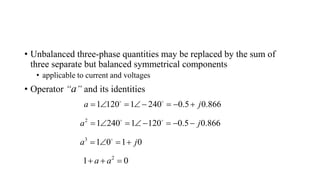
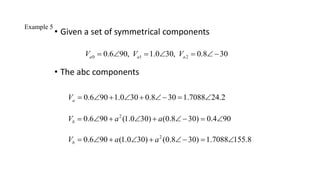
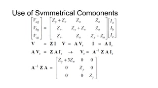
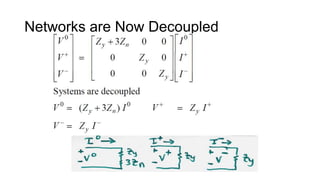
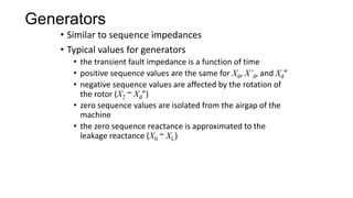
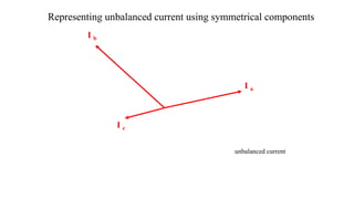
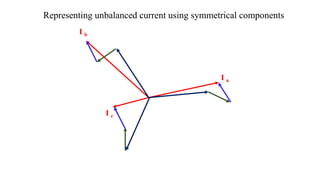
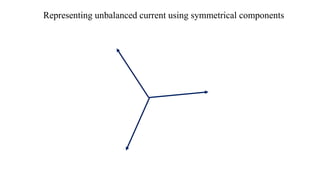
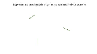
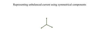
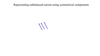
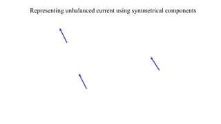
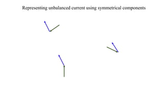
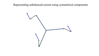
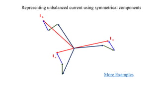
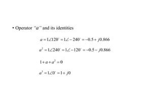
1. The document discusses symmetrical components, which allow representation of unbalanced three-phase quantities as the sum of three balanced components.
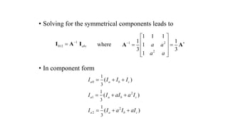
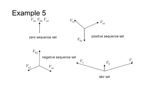
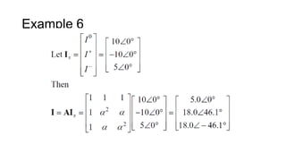
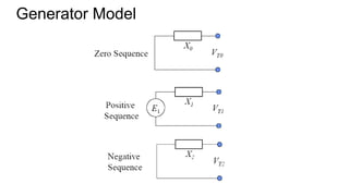
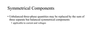
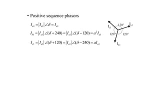
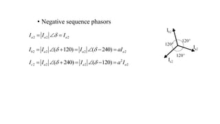
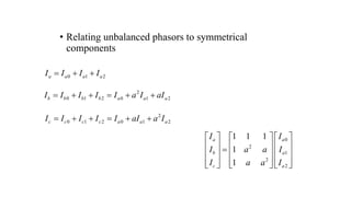
2. It introduces the positive, negative, and zero sequence components and the transformation matrix used to relate the symmetrical components to the original unbalanced quantities.
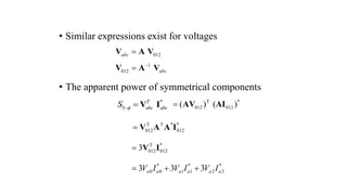
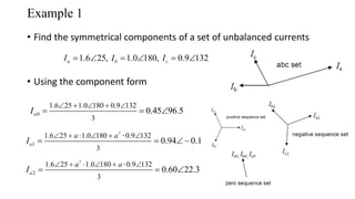
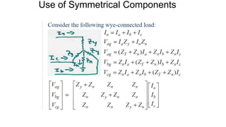
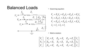
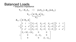
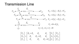
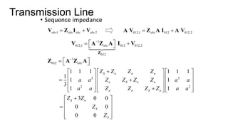
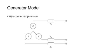
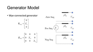
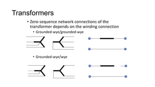
3. Symmetrical components are useful for simplifying analysis of unbalanced conditions like single line-to-ground faults in power systems. Sequence impedances can be used to model devices and transmission lines.


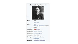
![In 1918 Charles Legeyt Fortescue presented a paper[3] which demonstrated that
any set of N unbalanced phasors (that is, any such polyphase signal) could be
expressed as the sum of N symmetrical sets of balanced phasors, for values of N
that are prime. Only a single frequency component is represented by the phasors.
In 1943 Edith Clarke published a textbook giving a method of use of
symmetrical components for three-phase systems that greatly simplified
calculations over the original Fortescue paper.[4] In a three-phase system, one set
of phasors has the same phase sequence as the system under study (positive
sequence; say ABC), the second set has the reverse phase sequence (negative
sequence; ACB), and in the third set the phasors A, B and C are in phase with
each other (zero sequence, the common-mode signal). Essentially, this method
converts three unbalanced phases into three independent sources, which
makes asymmetric fault analysis more tractable.](https://image.slidesharecdn.com/powersystemschapter1lecture3symmetricalcomponents-220107115051/85/Power-systems-symmetrical-components-18-320.jpg)
![Edith Clarke (February 10, 1883 – October 29,
1959) was the first woman to be professionally
employed as an electrical engineer in the United
States,[1] and the first female professor of
electrical engineering in the country.[2] She was
the first woman to deliver a paper at
the American Institute of Electrical Engineers,
the first female engineer whose professional
standing was recognized by Tau Beta Pi, and the
first woman named as a Fellow of the American
Institute of Electrical Engineers. She specialized
in electrical power system analysis[3] and
wrote Circuit Analysis of A-C Power Systems.[4]](https://image.slidesharecdn.com/powersystemschapter1lecture3symmetricalcomponents-220107115051/85/Power-systems-symmetrical-components-19-320.jpg)
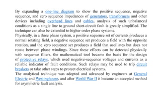
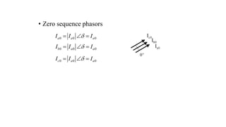

![• In matrix notation
• or
• [A] is the symmetrical components transformation
matrix
0
2
1
2
2
1 1 1
1
1
a a
b a
c a
I I
I a a I
I a a I
2
2
1 1 1
1
1
a a
a a
A
abc 012
I = A I where](https://image.slidesharecdn.com/powersystemschapter1lecture3symmetricalcomponents-220107115051/85/Power-systems-symmetrical-components-28-320.jpg)