Nodal analysis is a technique to analyze electrical circuits using Kirchhoff's Current Law (KCL). It involves writing nodal equations for each node in the circuit where three or more branches meet.
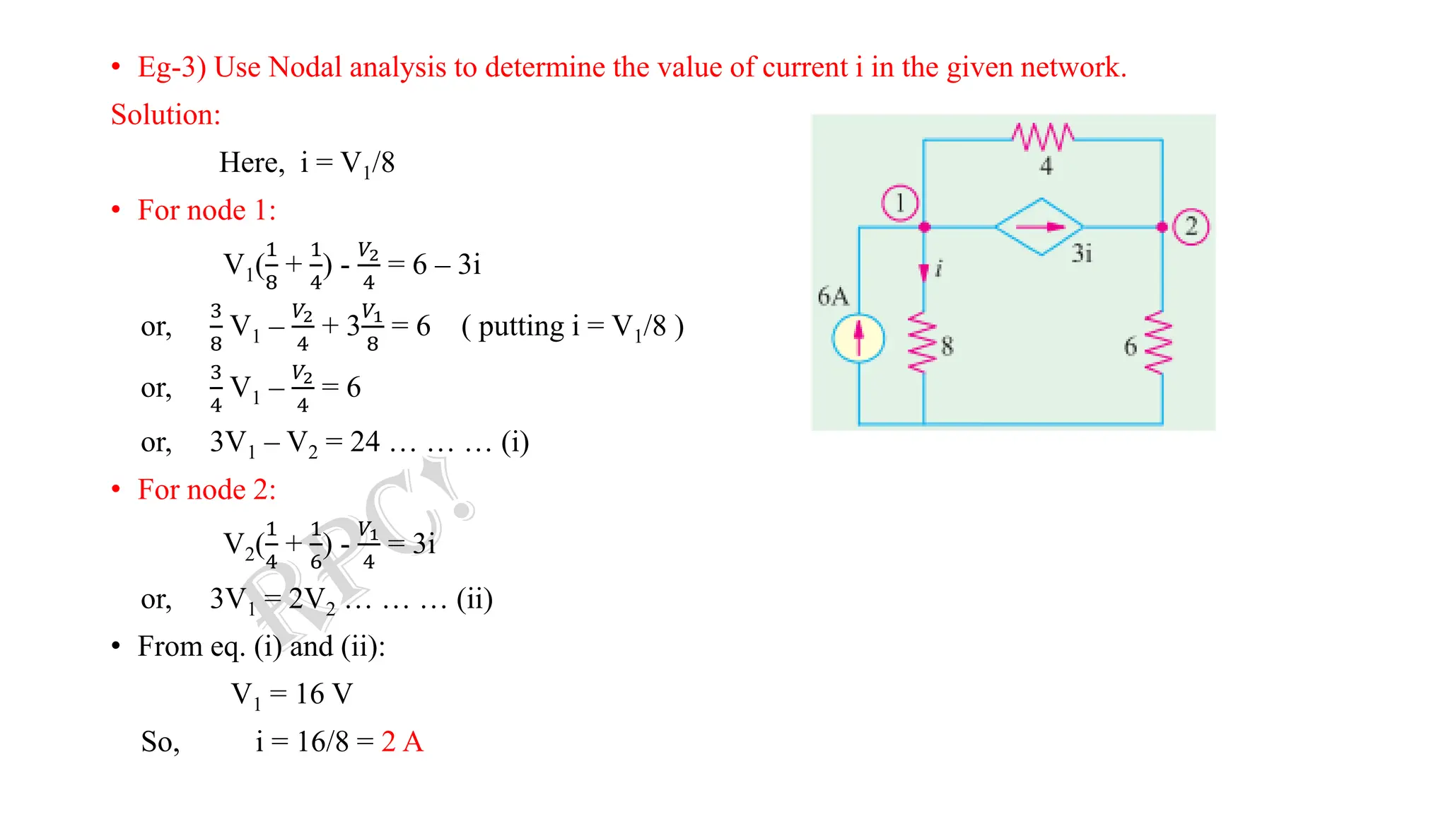
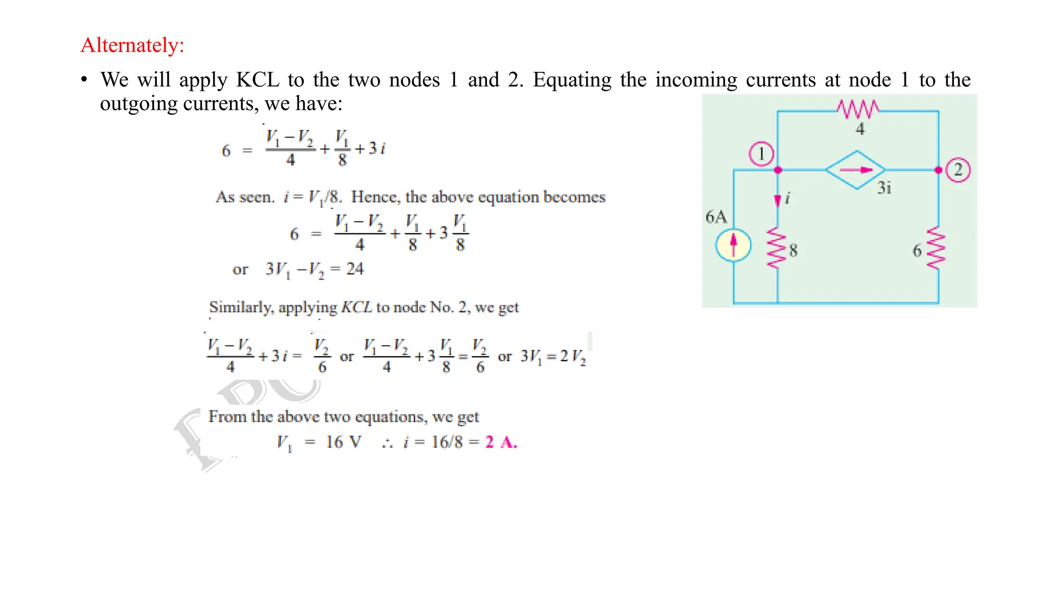
The document discusses nodal analysis through examples. It explains how to write nodal equations for each node by equating the sum of incoming currents to the sum of outgoing currents. The equations relate the node voltages to branch currents using Ohm's law. Solving the system of nodal equations determines the node voltages and allows calculating branch currents. The document also discusses applying nodal analysis to circuits with current sources.
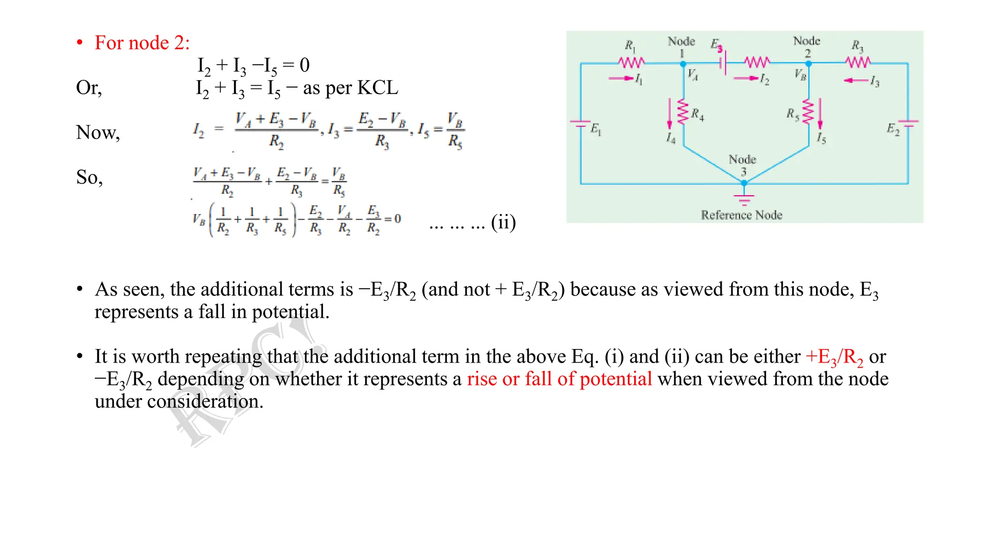
![CASE I:
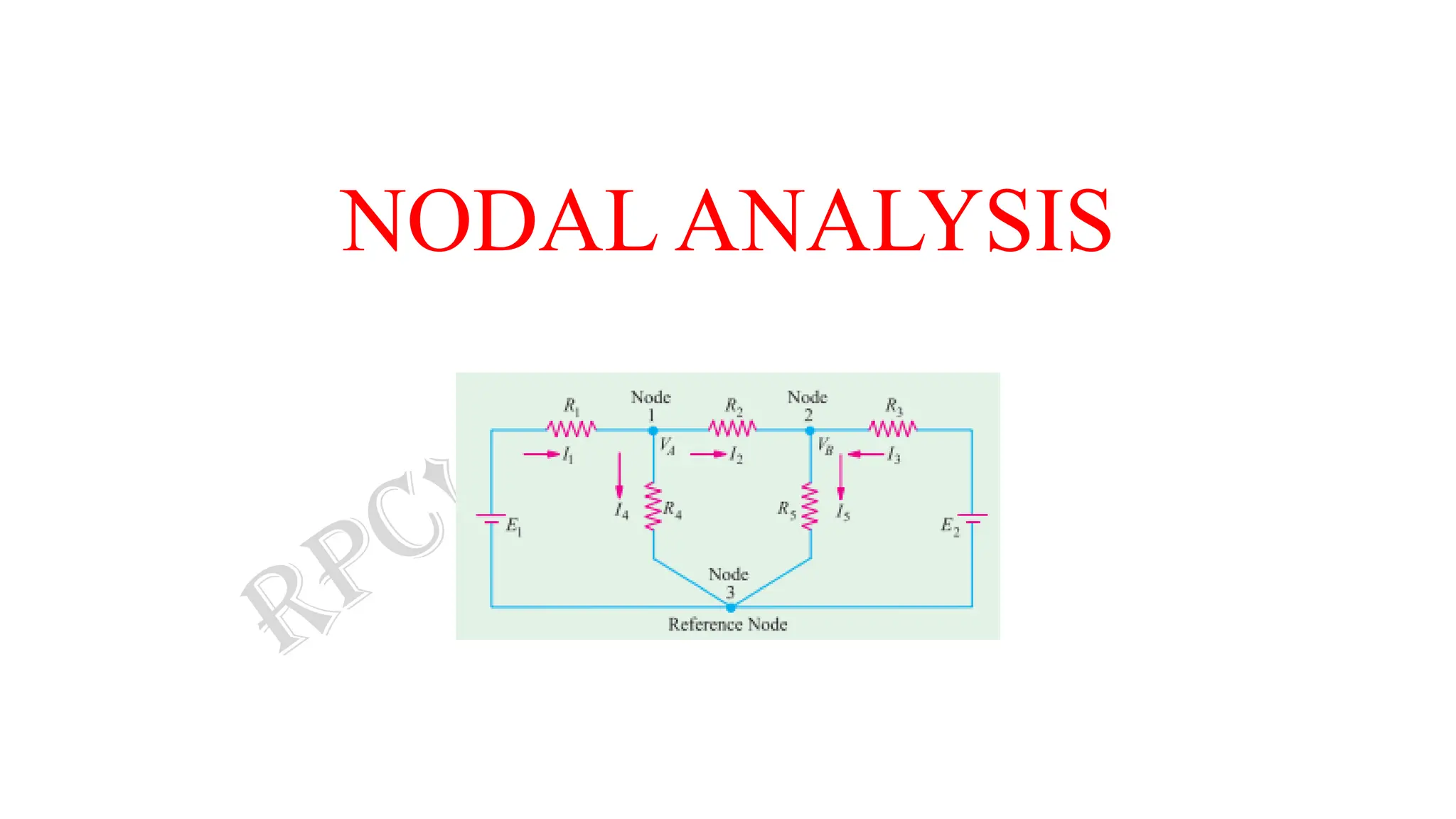
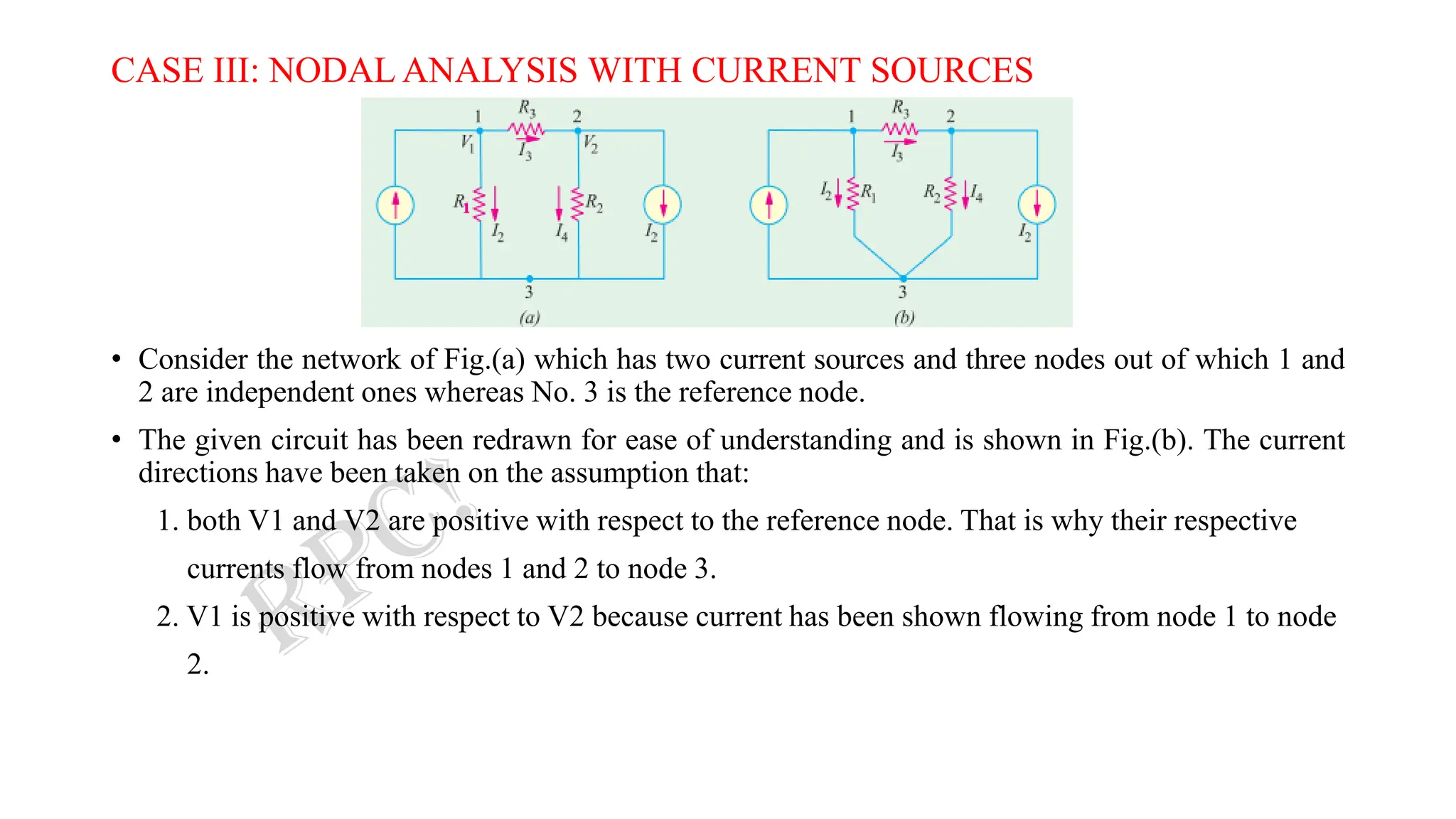
• Consider the circuit of figure below which has three nodes.
• One of these i.e. node 3 has been taken in as the reference
node.
• VA represents the potential of node 1 with reference to the
reference node 3.
• Similarly, VB is the potential difference between node 2 and node 3.
• Let the current directions, which have been chosen arbitrary, be as shown.
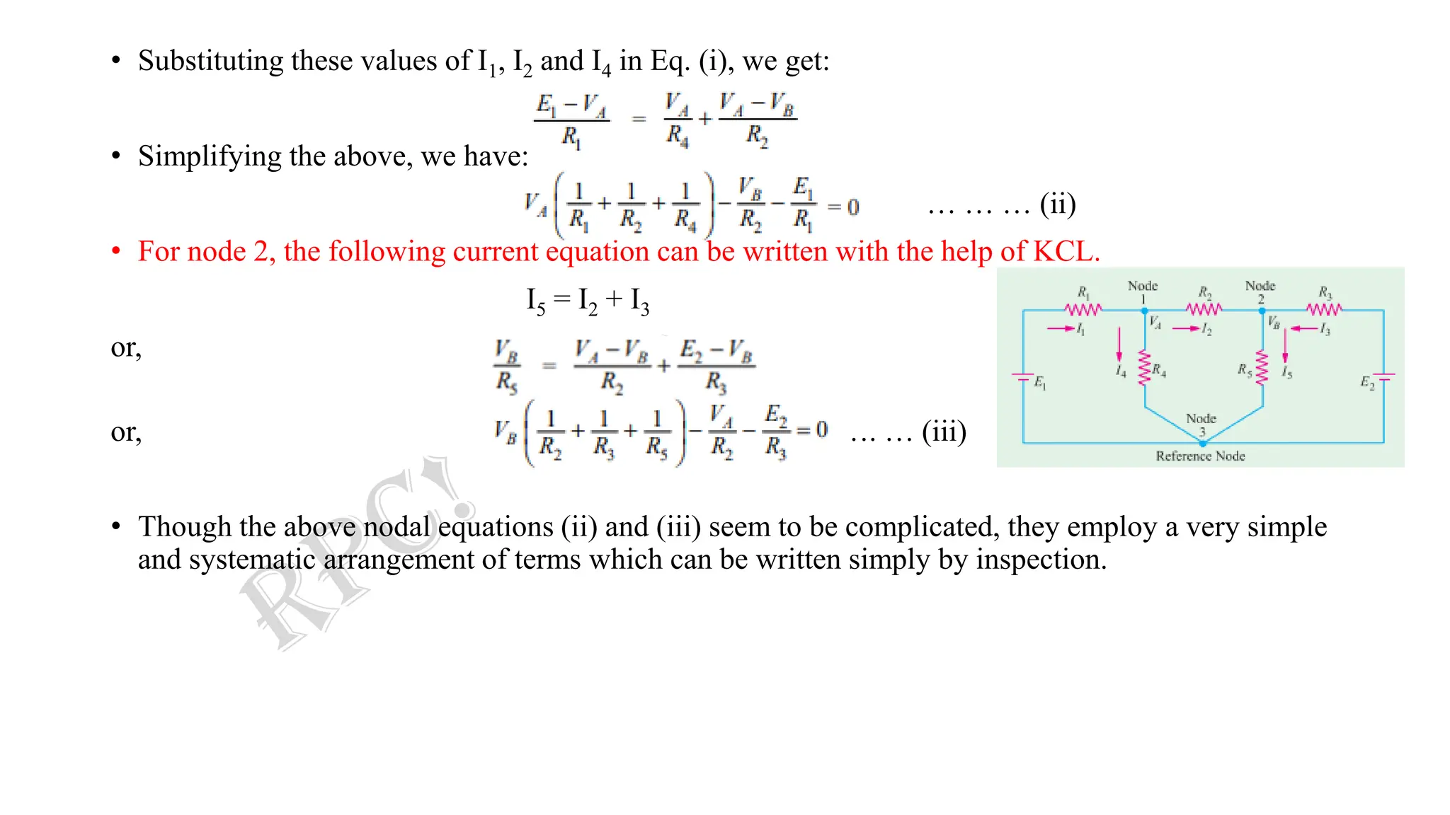
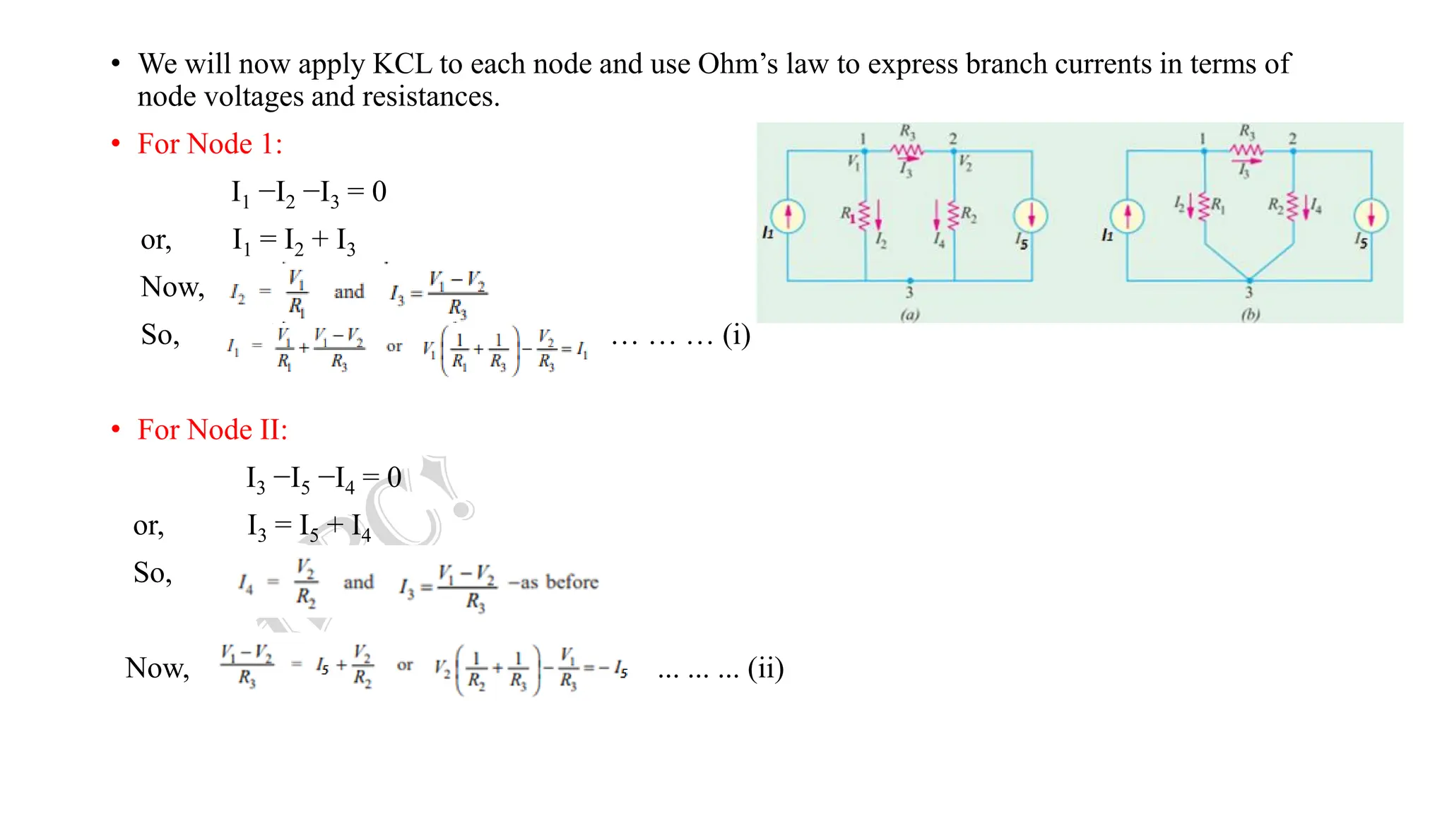
• For node 1, the following current equation can be written with the help of KCL.
I1 = I4 + I2 ... … … (i)
Now, I1R1 = E1 −VA [Applying KVL in Mesh (i)]
∴ I1 = (E1 −VA) /R1
And, I4 = VA/R4
Also, I2R2 = VA −VB ( since, VA > VB) [Applying KVL in Mesh (ii)]
∴ I2 = (VA −VB) /R2](https://image.slidesharecdn.com/2-231011231508-57f8d903/75/2-Nodal-Analysis-Complete-pdf-3-2048.jpg)
![• Solving for the different voltages, we have:
• So,
I1 = (V1 −V2) × 1 = (− 1.5 − 0.7) × 1 = −2.2 A
I2 = (V3 −V1) × 2 = [− 1.6 − (− 1.5)] × 2 = −0.2 A
I4 = V2 × 4 = 4 × (7/10) = 2.8 A
I3 = 2 + 2.8 = 4.8 A
• As seen, I1 and I2 flow in directions opposite to those originally assumed.](https://image.slidesharecdn.com/2-231011231508-57f8d903/75/2-Nodal-Analysis-Complete-pdf-23-2048.jpg)