Downloaded 120 times
![7
( )
( )
[ ]
0 120 240
n
cos0 sin0 cos120 sin120 cos240 sin 240
1 3 1 3
1 0 0.
2 2
:
( ) ,
I 0
22
o
j j j
a b c a
o o
a
a
where
Setting the result for curren
V V
t
V V e e e
KCL in the circuit before we obtai
V j
n
V j j j
j
− −
+ + = + + =
= + + − + − =
= + − − − + = ÷ ÷
=
o o
o o o o
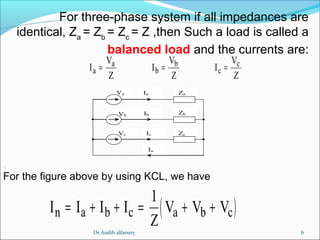
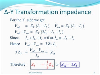
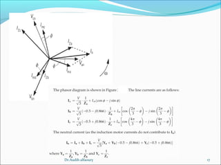
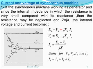
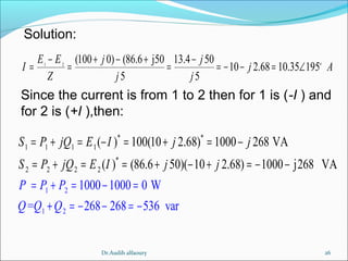
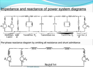
Since the current flowing though the fourth wire is zero, the neutral wire can be
removed and the system is named three wires system
n’n
Ia ZVa
Ic ZVc
Ib ZVb
Dr.Audih alfaoury](https://image.slidesharecdn.com/electricalpowersystemanalysislecture1-150318030016-conversion-gate01/85/power-system-analysis-lecture-1-7-320.jpg)

![13
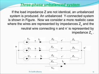
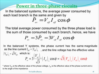
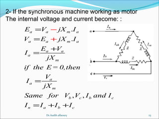
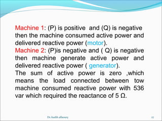
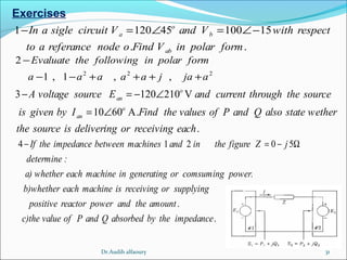
Example: A balance 3Φ system has Vab=173.2 0o
V and a(Y) load is connected with ZL=10 20o
.Assuming ABC system find the voltage and
current for all phases.
Solution:
[ ] [ ] [ ]
[ ] [ ] [ ]
[ ]
[ ]
173.2 0 V , 173.2 240 V , 173.2 120 V
173.2 173.2 173.2
0 30 V , 240 30 V , 120 30 V
3 3 3
:
100 30
10 50 A
10 20
100 210
10 190 A
10 20
100
o o o
ab bc ca
o o o o o o
an bn cn
o
oan
an o
L
o
obn
bn o
L
an
an
L
V V V
V V V
And the current is
V
I
Z
V
I
Z
V
I
Z
= ∠ = ∠ = ∠
= ∠ − = ∠ − = ∠ −
∠ −
= = = ∠ −
∠
∠
= = = ∠
∠
= = [ ]
90
10 70 A
10 20
o
o
o
∠
= ∠
∠
Vab
Dr.Audih alfaoury](https://image.slidesharecdn.com/electricalpowersystemanalysislecture1-150318030016-conversion-gate01/85/power-system-analysis-lecture-1-13-320.jpg)
![19
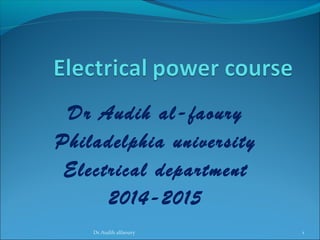
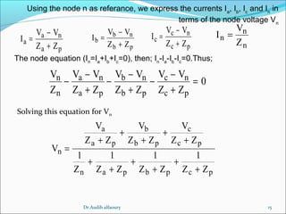
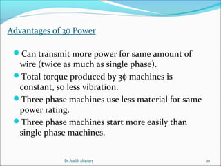
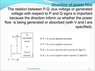
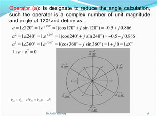
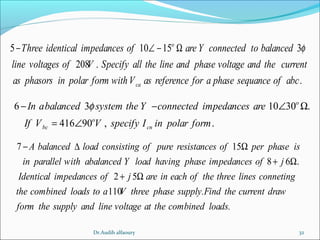
In power term the active power is: [ ]3 . cos ,LLLLP V I Wφ=
( ) ( )3 sinav eff effL L
Q V I φ=
[ ]3 . sin ,LL LL
Q V I VArφ=In power term the reactive is:
.
Same for reactive power
The square root of the sum of (P) and (Q) is the apparent power (S)
[ ]2 2 2 2
( . cos ) ( . sin ) ,S P jQ P Q V I V I V I VAφ φ= + = + = + =
1
2 2
cos , .sin
,and cos cos(tan )
cos sin
From powe triangle we have P S Q S
P Q Q P P
S
P S P Q
φ φ
φ
φ φ
−
= =
= = = = =
+
Dr.Audih alfaoury](https://image.slidesharecdn.com/electricalpowersystemanalysislecture1-150318030016-conversion-gate01/85/power-system-analysis-lecture-1-19-320.jpg)

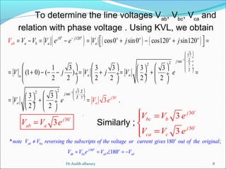
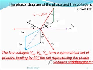
This document summarizes key concepts about three-phase systems. It defines a three-phase system as having three sinusoidal voltages differing in phase by 120 degrees. The voltages can form a positive or negative sequence. Three-phase systems are commonly used for power generation, transmission, and distribution due to their ability to transmit more power with less material. Formulas are provided for calculating line voltages, currents, and power in balanced and unbalanced three-phase systems. Advantages of three-phase systems like constant torque and easier starting of motors are also discussed.