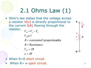
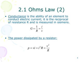
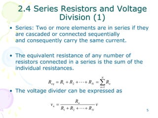
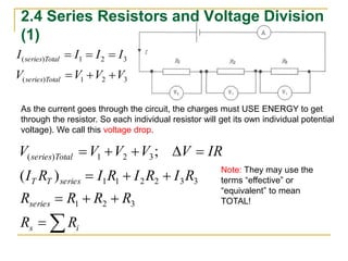
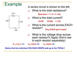
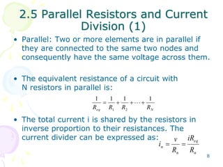
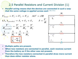
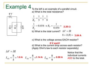
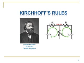
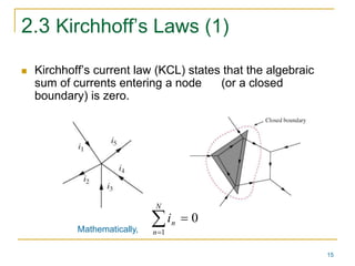
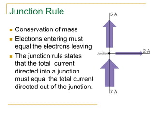
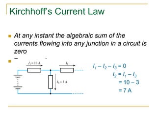
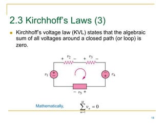
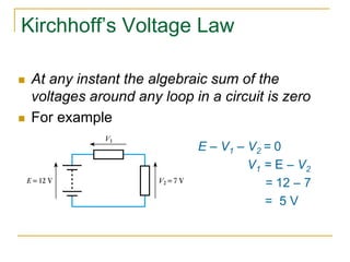
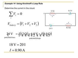
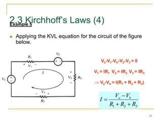
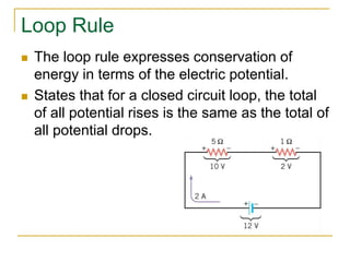
Lecture 2 
Basic Circuit Laws
2 
Basic Circuit Laws 
2.1 Ohm’s Law. 
2.2 Nodes, Branches, and Loops. 
2.3 Kirchhoff’s Laws. 
2.4 Series Resistors and Voltage Division. 
2.5 Parallel Resistors and Current Division. 
2.6 Wye-Delta Transformations.
3 
2.1 Ohms Law (1) 
• Ohm’s law states that the voltage across 
a resistor V(v) is directly proportional to 
the current I(A) flowing through the 
resistor. 
V  V  
V 
ab a b 
V  
I 
ab 
R 
R 
 
 
constant of proportionality 
Resistance 
V  
IR 
IR 
ab 
 
 
• When R=0 short circuit 
• When R=  open circuit. 
a 
b
4 
2.1 Ohms Law (2) 
• Conductance is the ability of an element to 
conduct electric current; it is the reciprocal 
of resistance R and is measured in siemens. 
i 
v 
1 
G   
R 
• The power dissipated by a resistor: 
v 
R 
p vi i R 
2 
2   
2.4 Series Resistors and Voltage 
5 
Division (1) 
• Series: Two or more elements are in series if they 
are cascaded or connected sequentially 
and consequently carry the same current. 
• The equivalent resistance of any number of 
resistors connected in a series is the sum of the 
individual resistances. 
N 
 
eq N n R R R R R 
 
        
n 
1 
1 2 
• The voltage divider can be expressed as 
v 
R 
R R R 
v 
N 
n 
 
n       
1 2
2.4 Series Resistors and Voltage Division 
(1) 
I I I I 
series Total 
   
( ) 1 2 3 
V V V V 
series Total 
   
( ) 1 2 3 
As the current goes through the circuit, the charges must USE ENERGY to get 
through the resistor. So each individual resistor will get its own individual potential 
voltage). We call this voltage drop. 
V  V  V  V  V  
IR 
series Total 
( ) 1 2 3 
( ) 
; 
I R I R I R I R 
T T series 
R  R  R  
R 
series 
 
   
1 2 3 
R R 
s i 
1 1 2 2 3 3 
Note: They may use the 
terms “effective” or 
“equivalent” to mean 
TOTAL!
Example 
A series circuit is shown to the left. 
a) What is the total resistance? 
R(series) = 1 + 2 + 3 = 6W 
b) What is the total current? 
V=IR 12=I(6) I = 2A 
c) What is the current across EACH 
resistor? 
They EACH get 2 amps! 
d) What is the voltage drop across 
each resistor?( Apply Ohm's law 
to each resistor separately) 
V1W(2)(1) 2 V V3W=(2)(3)= 6V V2W=(2)(2)= 4V 
Notice that the individual VOLTAGE DROPS add up to the TOTAL!!
2.5 Parallel Resistors and Current 
8 
Division (1) 
• Parallel: Two or more elements are in parallel if 
they are connected to the same two nodes and 
consequently have the same voltage across them. 
• The equivalent resistance of a circuit with 
N resistors in parallel is: 
1 1 1 1 
       
R R R R 
eq 1 2 
N • The total current i is shared by the resistors in 
inverse proportion to their resistances. The 
current divider can be expressed as: 
eq 
v 
i   
n R 
n 
n 
iR 
R
2.5 Parallel Resistors and Current Division (1) 
• Parallel wiring means that the devices are connected in such a way 
that the same voltage is applied across each device. 
V  V  V  V  V  
IR 
1 2 3 
; 
    
1 2 3 
V 
R 
V 
   
R 
V 
R 
1 2 3 
Total 
( ) 
T parallel 
parallel 
1 1 1 1 
R R R R 
1 2 3 
V 
1 1 
• Multiple paths are present. 
• When two resistors are connected in parallel, each receives current 
from the battery as if the other was not present. 
• Therefore the two resistors connected in parallel draw more current 
than does either resistor alone. 
R 
V 
R 
I I I I I 
p 
   
R3 
 
P i i R R 
I3
Example 4 
To the left is an example of a parallel circuit. 
a) What is the total resistance? 
1 
1 1 
   
1 
1 
    
0.454 
0.454 
R 
P 
1 
9 
7 
5 
P 
p 
R 
R 
2.20 W 
V IR 
  
8 I (R) 
  
b) What is the total current? 
3.64 A 
c) What is the voltage across EACH resistor? 
8 V each! 
d) What is the current drop across each resistor? 
(Apply Ohm's law to each resistor separately) 
V IR 
  
8 
8 
8 
5 7 9 I I I 
      
W 5 
W 7 
W 9 
1.6 A 1.14 A 0.90 A 
Notice that the 
individual currents 
ADD to the total.
11 
Gustav Kirchhoff 
1824-1887 
German Physicist
2.2 Nodes, Branches and Loops (1) 
12 
 A branch represents a single element such as a 
voltage source or a resistor. 
 A node is the point of connection between two 
or more branches. 
 A loop is any closed path in a circuit.
13 
2.2 Nodes, Branches and Loops (2) 
Example 1 
Original circuit 
Equivalent circuit 
How many branches, nodes and loops are there? 
4 Branches 
3 Nodes 
4 loops
2.2 Nodes, Branches and Loops (3) 
14 
Example 2 Should we consider it as one 
branch or two branches? 
How many branches, nodes and loops are there? 
7 Branches 
4 Nodes 
4 loops
15 
2.3 Kirchhoff’s Laws (1) 
 Kirchhoff’s current law (KCL) states that the algebraic 
sum of currents entering a node (or a closed 
boundary) is zero. 
0 
  
1 
N 
n 
n i 
Mathematically,
Junction Rule 
 Conservation of mass 
 Electrons entering must 
equal the electrons leaving 
 The junction rule states 
that the total current 
directed into a junction 
must equal the total current 
directed out of the junction.
Kirchhoff’s Current Law 
 At any instant the algebraic sum of the 
currents flowing into any junction in a circuit is 
zero 
 For example 
I1 – I2 – I3 = 0 
I2 = I1 – I3 
= 10 – 3 
= 7 A
18 
2.3 Kirchhoff’s Laws (3) 
 Kirchhoff’s voltage law (KVL) states that the algebraic 
sum of all voltages around a closed path (or loop) is 
zero. 
  
Mathematically, 0 
1 
M 
m 
n v
Kirchhoff’s Voltage Law 
 At any instant the algebraic sum of the 
voltages around any loop in a circuit is zero 
 For example 
E – V1 – V2 = 0 
V1 = E – V2 
= 12 – 7 
= 5 V
Example 14 Using Kirchhoff’s Loop Rule 
Determine the current in the circuit. 
  
i 
 1(   )  2   (   ) 
24 V  I 12 W  6.0 V I 8.0 W 
potential drops 
potential rises 
18 V  
20 I 
I 
 
0.90 A 
i V 0 
( ) 1 2 3 V V V V battery   
21 
2.3 Kirchhoff’s Laws (4) Example 5 
 Applying the KVL equation for the circuit of the figure 
below. 
Va-V1-Vb-V2-V3 = 0 
V1 = IR1 V2 = IR2 V3 = IR3 
 Va-Vb = I(R1 + R2 + R3) 
V  
V 
I a b 
R  R  
R 
1 2 3 
Loop Rule 
 The loop rule expresses conservation of 
energy in terms of the electric potential. 
 States that for a closed circuit loop, the total 
of all potential rises is the same as the total of 
all potential drops.

Analogue electronics lec (2)

  • 1.
    Lecture 2 BasicCircuit Laws
  • 2.
    2 Basic CircuitLaws 2.1 Ohm’s Law. 2.2 Nodes, Branches, and Loops. 2.3 Kirchhoff’s Laws. 2.4 Series Resistors and Voltage Division. 2.5 Parallel Resistors and Current Division. 2.6 Wye-Delta Transformations.
  • 3.
    3 2.1 OhmsLaw (1) • Ohm’s law states that the voltage across a resistor V(v) is directly proportional to the current I(A) flowing through the resistor. V  V  V ab a b V  I ab R R   constant of proportionality Resistance V  IR IR ab   • When R=0 short circuit • When R=  open circuit. a b
  • 4.
    4 2.1 OhmsLaw (2) • Conductance is the ability of an element to conduct electric current; it is the reciprocal of resistance R and is measured in siemens. i v 1 G   R • The power dissipated by a resistor: v R p vi i R 2 2   
  • 5.
    2.4 Series Resistorsand Voltage 5 Division (1) • Series: Two or more elements are in series if they are cascaded or connected sequentially and consequently carry the same current. • The equivalent resistance of any number of resistors connected in a series is the sum of the individual resistances. N  eq N n R R R R R          n 1 1 2 • The voltage divider can be expressed as v R R R R v N n  n       1 2
  • 6.
    2.4 Series Resistorsand Voltage Division (1) I I I I series Total    ( ) 1 2 3 V V V V series Total    ( ) 1 2 3 As the current goes through the circuit, the charges must USE ENERGY to get through the resistor. So each individual resistor will get its own individual potential voltage). We call this voltage drop. V  V  V  V  V  IR series Total ( ) 1 2 3 ( ) ; I R I R I R I R T T series R  R  R  R series     1 2 3 R R s i 1 1 2 2 3 3 Note: They may use the terms “effective” or “equivalent” to mean TOTAL!
  • 7.
    Example A seriescircuit is shown to the left. a) What is the total resistance? R(series) = 1 + 2 + 3 = 6W b) What is the total current? V=IR 12=I(6) I = 2A c) What is the current across EACH resistor? They EACH get 2 amps! d) What is the voltage drop across each resistor?( Apply Ohm's law to each resistor separately) V1W(2)(1) 2 V V3W=(2)(3)= 6V V2W=(2)(2)= 4V Notice that the individual VOLTAGE DROPS add up to the TOTAL!!
  • 8.
    2.5 Parallel Resistorsand Current 8 Division (1) • Parallel: Two or more elements are in parallel if they are connected to the same two nodes and consequently have the same voltage across them. • The equivalent resistance of a circuit with N resistors in parallel is: 1 1 1 1        R R R R eq 1 2 N • The total current i is shared by the resistors in inverse proportion to their resistances. The current divider can be expressed as: eq v i   n R n n iR R
  • 9.
    2.5 Parallel Resistorsand Current Division (1) • Parallel wiring means that the devices are connected in such a way that the same voltage is applied across each device. V  V  V  V  V  IR 1 2 3 ;     1 2 3 V R V    R V R 1 2 3 Total ( ) T parallel parallel 1 1 1 1 R R R R 1 2 3 V 1 1 • Multiple paths are present. • When two resistors are connected in parallel, each receives current from the battery as if the other was not present. • Therefore the two resistors connected in parallel draw more current than does either resistor alone. R V R I I I I I p    R3  P i i R R I3
  • 10.
    Example 4 Tothe left is an example of a parallel circuit. a) What is the total resistance? 1 1 1    1 1     0.454 0.454 R P 1 9 7 5 P p R R 2.20 W V IR   8 I (R)   b) What is the total current? 3.64 A c) What is the voltage across EACH resistor? 8 V each! d) What is the current drop across each resistor? (Apply Ohm's law to each resistor separately) V IR   8 8 8 5 7 9 I I I       W 5 W 7 W 9 1.6 A 1.14 A 0.90 A Notice that the individual currents ADD to the total.
  • 11.
    11 Gustav Kirchhoff 1824-1887 German Physicist
  • 12.
    2.2 Nodes, Branchesand Loops (1) 12  A branch represents a single element such as a voltage source or a resistor.  A node is the point of connection between two or more branches.  A loop is any closed path in a circuit.
  • 13.
    13 2.2 Nodes,Branches and Loops (2) Example 1 Original circuit Equivalent circuit How many branches, nodes and loops are there? 4 Branches 3 Nodes 4 loops
  • 14.
    2.2 Nodes, Branchesand Loops (3) 14 Example 2 Should we consider it as one branch or two branches? How many branches, nodes and loops are there? 7 Branches 4 Nodes 4 loops
  • 15.
    15 2.3 Kirchhoff’sLaws (1)  Kirchhoff’s current law (KCL) states that the algebraic sum of currents entering a node (or a closed boundary) is zero. 0   1 N n n i Mathematically,
  • 16.
    Junction Rule Conservation of mass  Electrons entering must equal the electrons leaving  The junction rule states that the total current directed into a junction must equal the total current directed out of the junction.
  • 17.
    Kirchhoff’s Current Law  At any instant the algebraic sum of the currents flowing into any junction in a circuit is zero  For example I1 – I2 – I3 = 0 I2 = I1 – I3 = 10 – 3 = 7 A
  • 18.
    18 2.3 Kirchhoff’sLaws (3)  Kirchhoff’s voltage law (KVL) states that the algebraic sum of all voltages around a closed path (or loop) is zero.   Mathematically, 0 1 M m n v
  • 19.
    Kirchhoff’s Voltage Law  At any instant the algebraic sum of the voltages around any loop in a circuit is zero  For example E – V1 – V2 = 0 V1 = E – V2 = 12 – 7 = 5 V
  • 20.
    Example 14 UsingKirchhoff’s Loop Rule Determine the current in the circuit.   i  1(   )  2   (   ) 24 V  I 12 W  6.0 V I 8.0 W potential drops potential rises 18 V  20 I I  0.90 A i V 0 ( ) 1 2 3 V V V V battery   
  • 21.
    21 2.3 Kirchhoff’sLaws (4) Example 5  Applying the KVL equation for the circuit of the figure below. Va-V1-Vb-V2-V3 = 0 V1 = IR1 V2 = IR2 V3 = IR3  Va-Vb = I(R1 + R2 + R3) V  V I a b R  R  R 1 2 3 
  • 22.
    Loop Rule The loop rule expresses conservation of energy in terms of the electric potential.  States that for a closed circuit loop, the total of all potential rises is the same as the total of all potential drops.