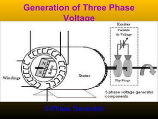
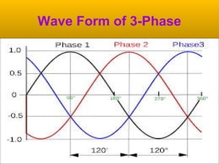
Three-phase systems have multiple voltages or currents that are displaced in time by 120 degrees. They provide advantages over single-phase systems like higher power capacity, self-starting motors, and more constant power output.
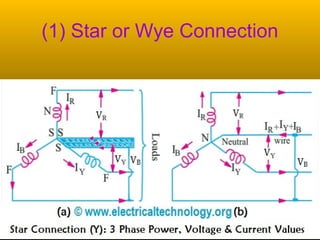
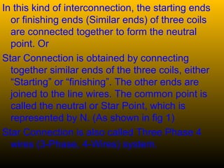
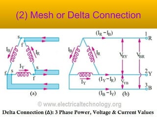
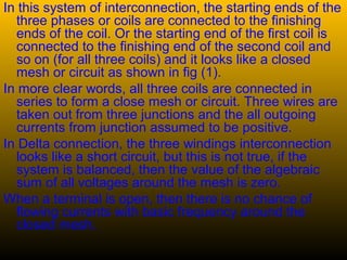
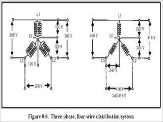
A 3-phase generator produces 3 voltages displaced by 120 degrees through its winding configuration. The voltages can be connected in either a star or delta configuration. In a star connection, the winding ends meet at a central neutral point. In a delta connection, the windings are connected in a closed loop.
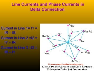
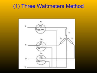
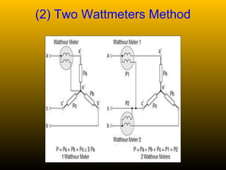
Power in a 3-phase circuit can be measured using either 3 wattmeters connected to each phase, or 2 wattmeters connected across different phase combinations to calculate total power.


![Phase Sequence of 3-Phase
System
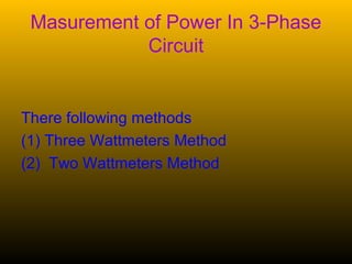
A three phase system of voltages (or currents) has a
sequence (or order) in which the phases reach a
particular position (for example peak value). This is
the natural sequence of the supply. According to usual
notation, we would call the sequence R-Y-B or A-B-C.
If we consider a balanced system of voltages (or
currents) they will have only the natural sequence, and
there will no other components present. However,
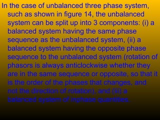
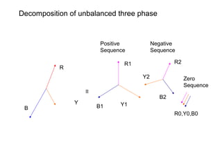
Fortescue has formulated that any unbalanced system
can be split up into a series of balanced systems.
[This is like saying that any force can be broken up
into its components along the x-axis, y-axis and z-axis.
The advantage of such a decomposition is in the
analysis of more than one quantity]](https://image.slidesharecdn.com/3-phaseaccircuit-151009135902-lva1-app6891/85/3-phase-ac-circuit-14-320.jpg)