Downloaded 104 times


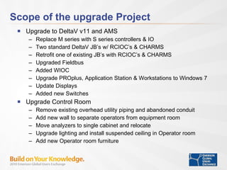

The document outlines the modernization project of the UT Pickle Research Center, including upgrades to charms I/O systems, controllers, and control room infrastructure. The project aims to enhance operational flexibility, improve data management, and streamline research processes in separation technologies. It discusses the project's planning and execution phases, highlighting newly integrated technologies and the benefits achieved for ongoing research and testing capabilities.


