Downloaded 137 times
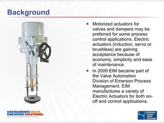
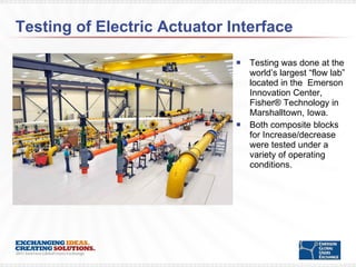
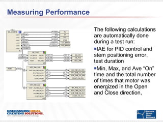
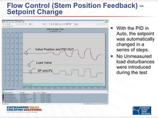
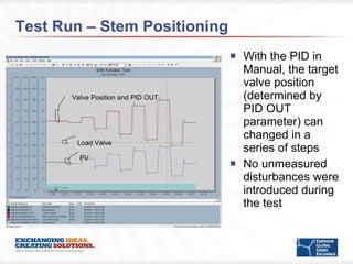
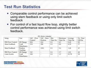

The document discusses the integration of motorized actuators with DeltaV control systems, highlighting the development of composite blocks that facilitate their use in control applications. It presents simulation results from tests conducted using HL series electric actuators, demonstrating how DeltaV can optimize control and reduce engineering costs with these actuators. Composite blocks are available for free at the Emerson Application Exchange, allowing easier access for engineers working with motorized valves.


![RF Circuit Design - [Ch1-1] Sinusoidal Steady-state Analysis](https://cdn.slidesharecdn.com/ss_thumbnails/ch1-1-150613064348-lva1-app6891-thumbnail.jpg?width=640&height=640&fit=bounds)


