Downloaded 790 times

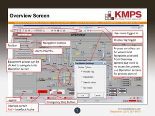
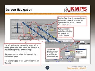
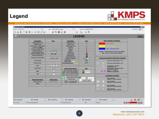
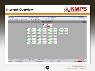
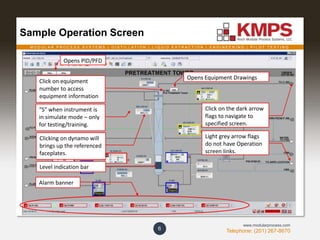
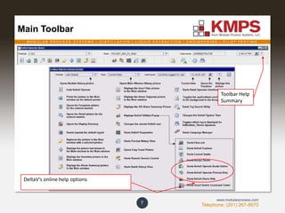
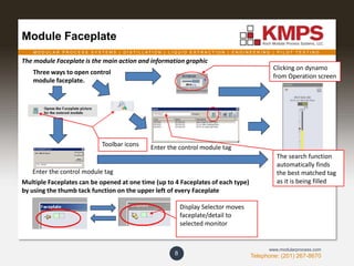
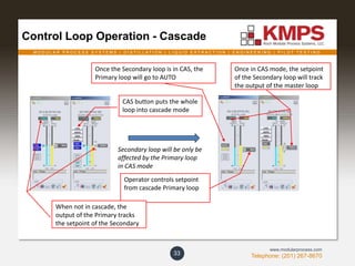
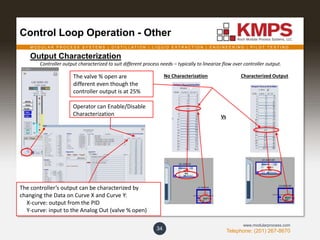
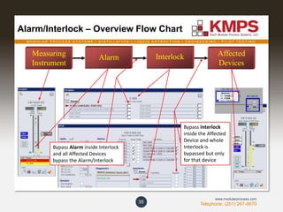
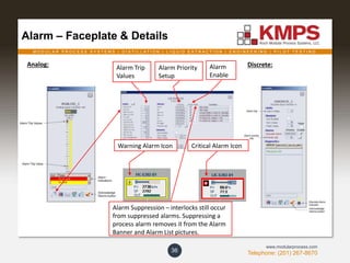
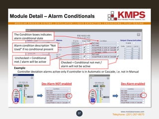
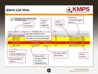
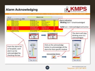
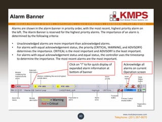
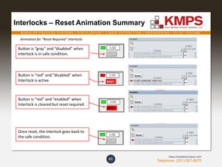
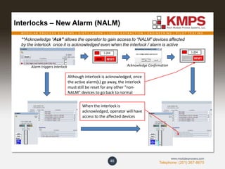
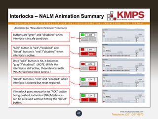
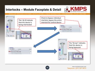


The document serves as a reference guide for DeltaV DCS operator training, outlining the controls and operation of the system. It details navigation through various screens and the use of equipment tags, as well as the different modes of operation for control devices like valves and motors. Additionally, it discusses alarm systems, faceplates for equipment control, and visual aids for monitoring process variables.


