Downloaded 926 times
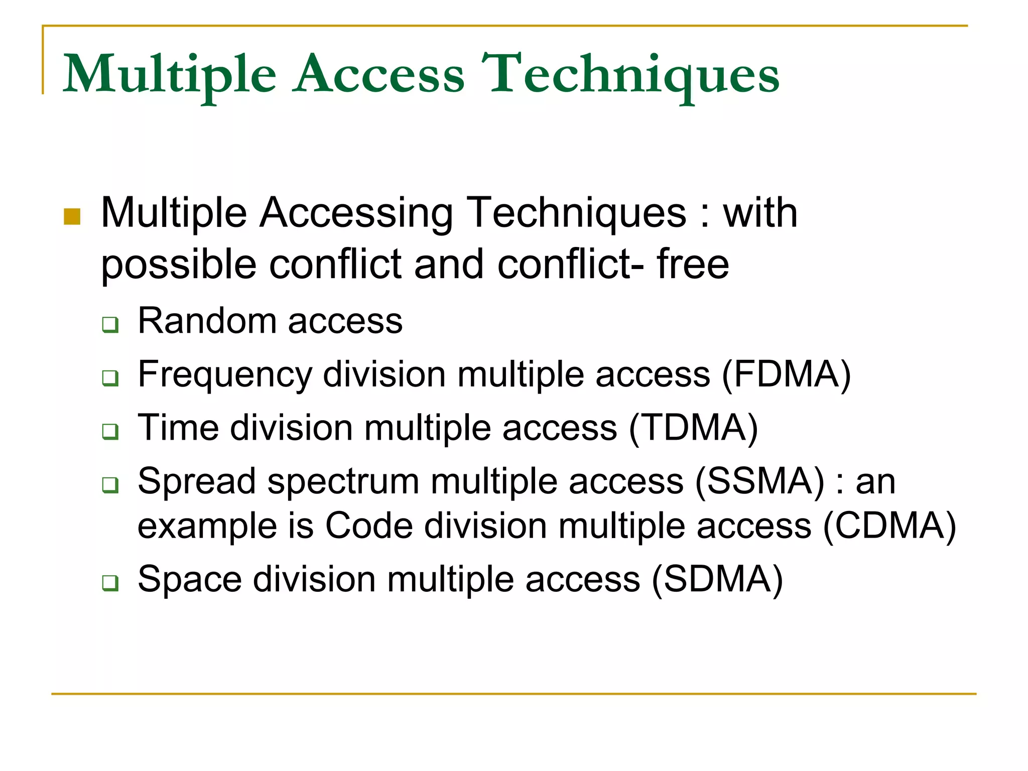


Multiple access techniques allow multiple users to share finite radio spectrum resources simultaneously. They can be categorized as narrowband or wideband. Common techniques include FDMA, TDMA, CDMA, and SDMA. FDMA divides the total bandwidth into narrow channels that are allocated to users. TDMA divides each channel into time slots that are allocated to users. CDMA spreads the signal over a wide bandwidth using pseudo-random codes and allows multiple signals to overlap in both time and frequency.


![B.I.T , MESRA [M.Tech] Assignment : MULTIPLE ACCESS TECHNIQUES FOR WIRELESS ...](https://cdn.slidesharecdn.com/ss_thumbnails/multipleaccesstechniquesassignmentfinal-170820115158-thumbnail.jpg?width=640&height=640&fit=bounds)


