Downloaded 629 times


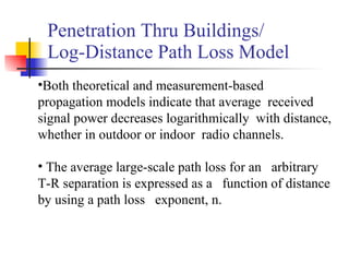


This document discusses different radio propagation models for both indoor and outdoor environments. It provides examples of common outdoor propagation models including the Longley-Rice model and Hata model. It also discusses indoor propagation models and key factors that influence indoor radio signals, such as building layout and construction materials. Common indoor path loss models include the log-distance path loss model and ITU indoor attenuation model. Radio propagation is influenced by factors like distance, environment, and signal penetration through buildings.